2006 LAND ROVER FRELANDER 2 belt
[x] Cancel search: beltPage 2201 of 3229
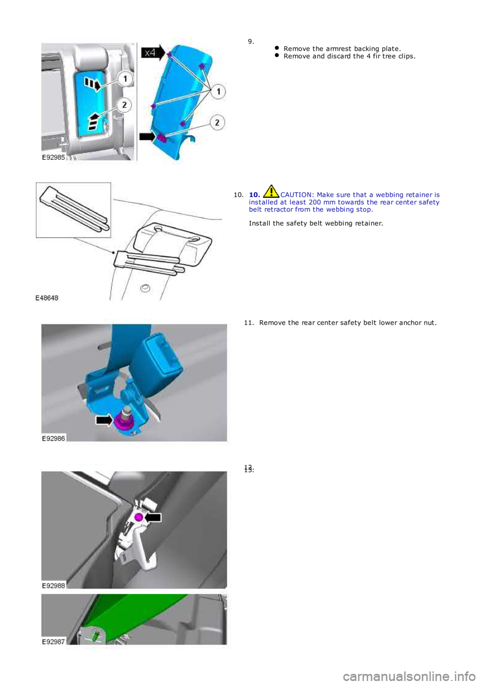
Remove t he armrest backing plat e.Remove and dis card t he 4 fir t ree cl ips .
9.
10. CAUTION: Make s ure t hat a webbing ret ainer isins t al led at l eas t 200 mm t owards t he rear cent er s afetybelt ret ract or from t he webbi ng s top.
Ins t all the safety belt webbi ng ret ai ner.
10.
Remove t he rear cent er safety bel t lower anchor nut .11.
12.13.
Page 2203 of 3229
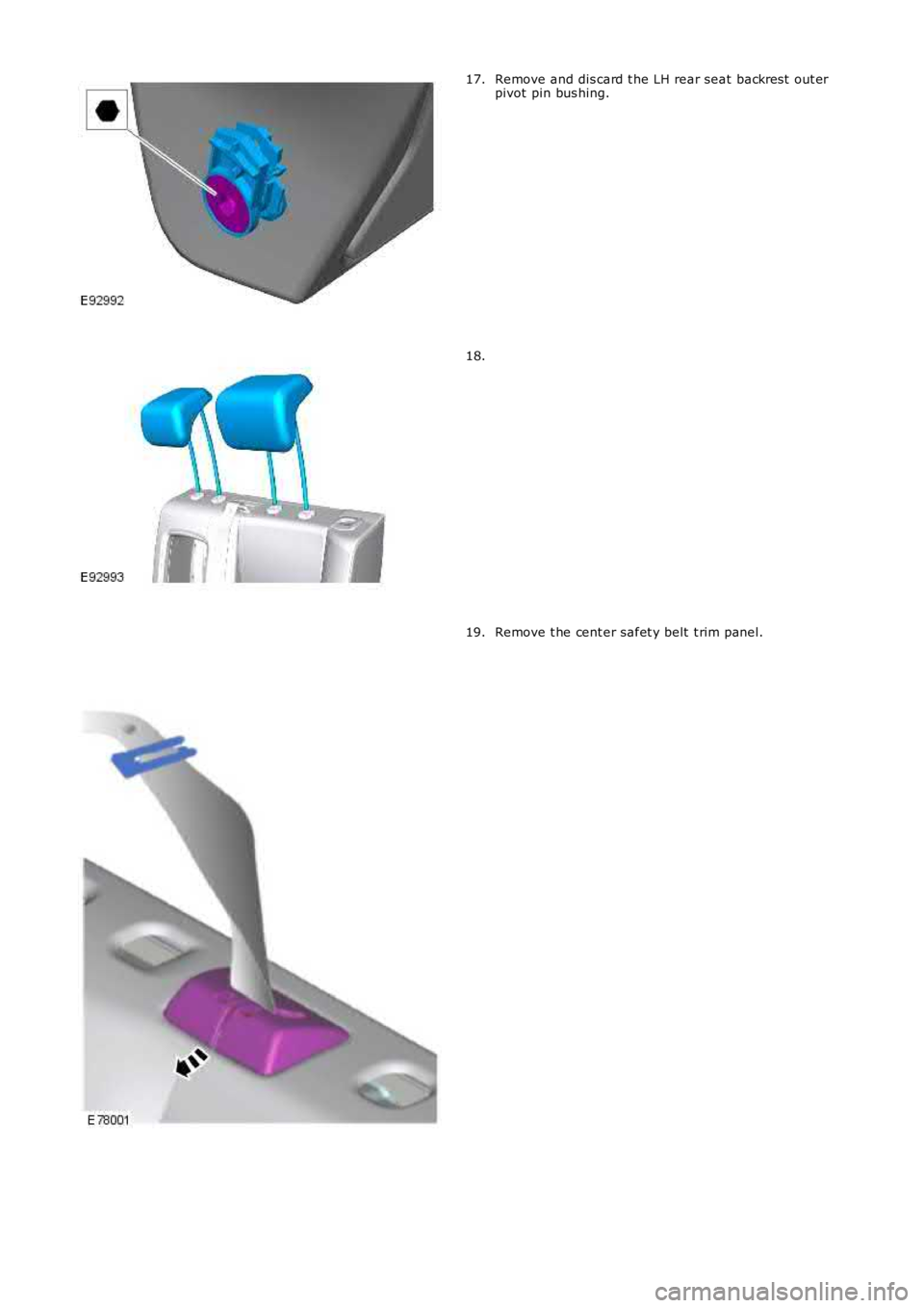
Remove and dis card t he LH rear seat backres t out erpivot pin bus hing.17.
18.
Remove t he cent er safet y belt t rim panel.19.
Page 2206 of 3229
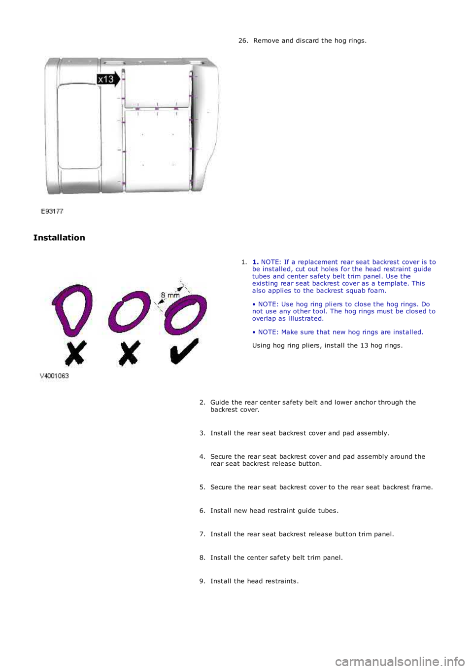
Remove and dis card t he hog rings.26.
Installation
1. NOTE: If a replacement rear seat backres t cover i s t obe ins t al led, cut out holes for the head rest rai nt gui detubes and center s afety bel t trim panel . Us e t heexi s ti ng rear s eat backres t cover as a t emplat e. Thisals o appli es to the backrest squab foam.
• NOTE: Us e hog ring pli ers t o clos e t he hog rings. Donot us e any ot her tool. The hog rings mus t be clos ed t ooverlap as i ll ust rat ed.
• NOTE: Make s ure t hat new hog ri ngs are i nst all ed.
Us ing hog ring pl iers , ins t al l the 13 hog ri ngs .
1.
Guide the rear center s afet y belt and l ower anchor t hrough t hebackrest cover.2.
Inst all t he rear s eat backres t cover and pad ass embly.3.
Secure t he rear s eat backres t cover and pad ass embl y around t herear s eat backres t rel eas e but ton.4.
Secure t he rear s eat backres t cover to the rear seat backrest frame.5.
Inst all new head res t rai nt gui de tubes .6.
Inst all t he rear s eat backres t releas e butt on t ri m panel.7.
Inst all t he cent er safet y belt t rim panel.8.
Inst all t he head res traints .9.
Page 2207 of 3229
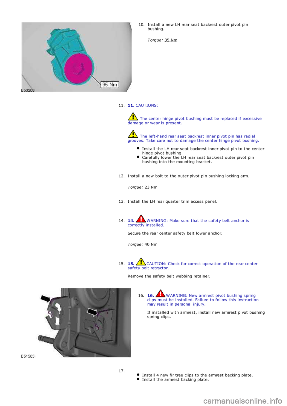
Ins t all a new LH rear s eat backres t out er pivot pi n
bushi ng.
T orque: 35 Nm 10.
11. CAUTIONS: The center hinge pi vot bus hing mus t be repl aced i f exces si ve
damage or wear is pres ent. The l eft -hand rear s eat backres t inner pivot pin has radial
grooves. Take care not t o damage t he cent er hi nge pivot bus hing.
Inst all t he LH rear s eat backres t inner pivot pin t o t he cent er
hinge pi vot bus hing. Carefully lower the LH rear s eat backres t out er pivot pin
bus hi ng int o t he mounti ng bracket . 11.
Inst all a new bol t to the out er pi vot pi n bushi ng locking arm.
T orque: 23 Nm 12.
Inst all t he LH rear quart er trim acces s panel .
13.
14. W ARNING: Make sure t hat t he s afet y bel t anchor is
correct ly i nst all ed.
Secure t he rear cent er s afety bel t lower anchor.
T orque: 40 Nm 14.
15. CAUTION: Check for correct operati on of the rear cent er
s afet y belt ret ract or.
Remove t he s afety bel t webbi ng ret ainer.
15. 16. W ARNING: New armrest pi vot bus hing s pri ng
clips must be ins tall ed. Fail ure to foll ow t hi s i ns t ructi on
may resul t in personal injury.
If i nst all ed wit h armres t , ins tall new armres t pi vot bus hi ng
s pring cl ips .
16.
Inst all 4 new fi r tree cl ips t o t he armres t backing pl ate. Inst all t he armrest backing plat e.17.
Page 2221 of 3229
Publi s hed: 11-May-2011
Seating - Front Seat Height Adjustment Motor
Removal and Inst all ati on
Removal
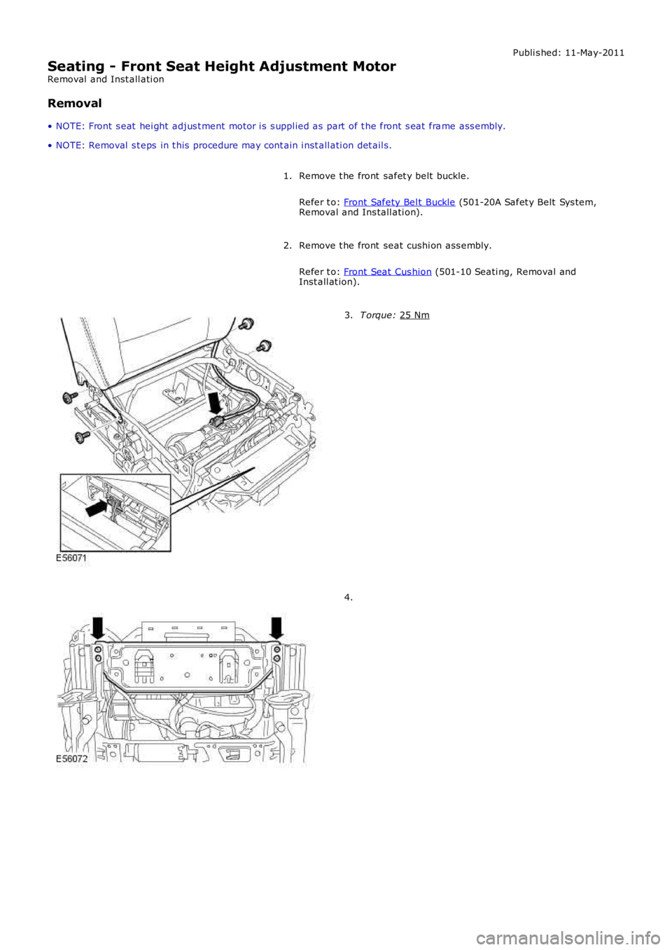
• NOTE: Front s eat hei ght adjus t ment motor i s s uppl ied as part of t he front s eat fra me ass embly.
• NOTE: Removal s t eps in t his procedure may cont ain i nst all ati on det ail s.
Remove t he front safet y belt buckle.
Refer t o: Front Safety Bel t Buckle (501-20A Safet y Belt Sys tem,
Removal and Ins tall ati on).
1.
Remove t he front seat cushi on ass embly.
Refer t o: Front Seat Cus hion (501-10 Seati ng, Removal and
Inst all at ion).
2. T orque:
25 Nm 3.
4.
Page 2260 of 3229
Publi s hed: 11-May-2011
Instrument Panel and Console - Instrument Panel
Des cript ion and Operat ion
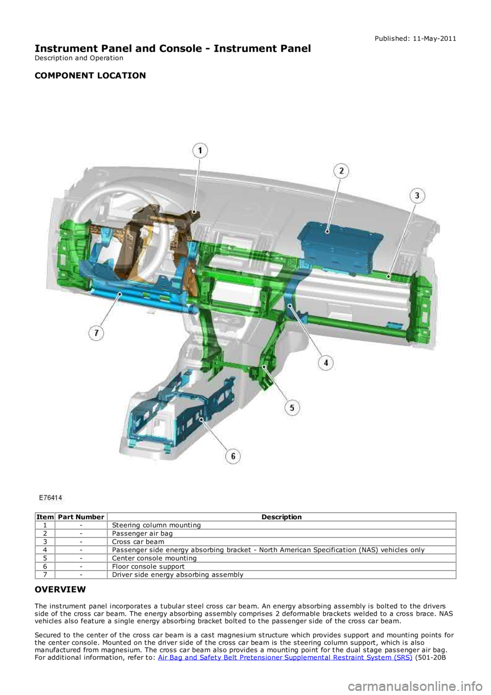
COMPONENT LOCATION
ItemPart NumberDescription1-St eering col umn mounti ng
2-Pas s enger air bag
3-Cross car beam4-Pas s enger s ide energy abs orbing bracket - Nort h American Speci fi cat ion (NAS) vehi cl es onl y
5-Cent er cons ol e mounti ng
6-Fl oor consol e s upport7-Driver s ide energy abs orbing as s embly
OVERVIEW
The ins t rument panel i ncorporat es a t ubul ar st eel cross car beam. An energy abs orbing as s embly i s bolt ed to the driverss ide of t he cros s car beam. The energy abs orbing as s embly compri s es 2 deformabl e brackets wel ded to a cros s brace. NASvehi cl es als o feat ure a s ingle energy abs orbi ng bracket bolt ed t o t he pass enger s i de of the cros s car beam.
Secured to the center of t he cros s car beam is a cas t magnes i um s t ructure which provides s upport and mounti ng points fort he cent er cons ol e. Mount ed on t he dri ver s ide of t he cros s car beam is the s t eering column support , which i s als omanufactured from magnes ium. The cros s car beam als o provi des a mounti ng poi nt for the dual s t age pas s enger air bag.For addit ional informat ion, refer t o: Air Bag and Safet y Belt Pretens ioner Supplement al Res traint Syst em (SRS) (501-20B
Page 2313 of 3229
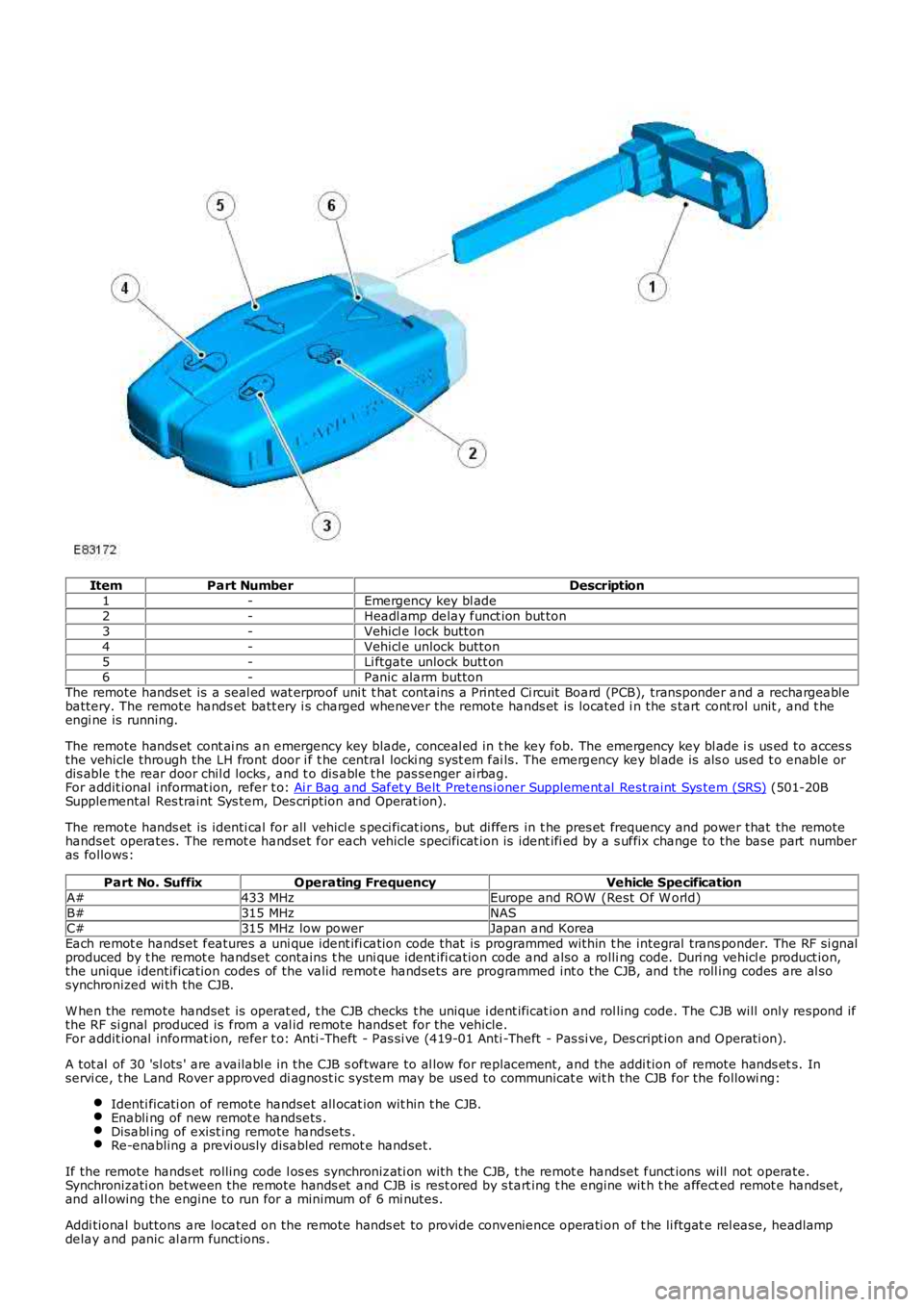
ItemPart NumberDescription1-Emergency key bl ade2-Headl amp delay funct ion but ton3-Vehicl e l ock button4-Vehicl e unlock button5-Li ftgate unlock butt on6-Panic alarm buttonThe remote hands et is a seal ed wat erproof uni t t hat contains a Printed Ci rcuit Board (PCB), transponder and a rechargeablebattery. The remote hands et batt ery i s charged whenever the remote hands et is located i n the s tart cont rol unit , and t heengi ne is running.
The remote hands et cont ai ns an emergency key blade, conceal ed in t he key fob. The emergency key bl ade i s us ed to acces sthe vehicle through the LH front door i f t he central locki ng syst em fai ls. The emergency key bl ade is als o us ed t o enable ordis able t he rear door chil d locks , and t o dis able t he pas senger ai rbag.For addit ional informat ion, refer t o: Ai r Bag and Safet y Belt Pretens ioner Supplement al Rest raint Sys tem (SRS) (501-20BSupplemental Res traint Sys tem, Des cription and Operat ion).
The remote hands et is identi cal for all vehicl e s peci ficat ions, but di ffers in t he pres et frequency and power that the remotehandset operates. The remot e handset for each vehicle specificat ion is ident ifi ed by a s uffix change to the base part numberas follows:
Part No. SuffixOperating FrequencyVehicle SpecificationA#433 MHzEurope and ROW (Rest Of W orld)B#315 MHzNASC#315 MHz low powerJapan and KoreaEach remot e handset features a uni que ident ifi cation code that is programmed within t he integral trans ponder. The RF si gnalproduced by t he remot e handset contains t he uni que ident ifi cation code and also a rolli ng code. Duri ng vehicl e product ion,the unique identification codes of the valid remot e handsets are programmed int o the CJB, and the roll ing codes are al sosynchronized wi th the CJB.
W hen the remote handset is operat ed, t he CJB checks t he unique i dent ificat ion and rol ling code. The CJB will only respond ifthe RF si gnal produced is from a val id remote hands et for the vehicle.For addit ional informat ion, refer t o: Anti -Theft - Pas si ve (419-01 Anti -Theft - Pas si ve, Des cript ion and Operati on).
A tot al of 30 'sl ots ' are availabl e in the CJB s oftware to al low for repl acement, and the addi tion of remote hands et s. Inservi ce, t he Land Rover approved di agnost ic system may be us ed to communicat e wit h the CJB for the followi ng:
Identi ficati on of remote handset all ocat ion wit hin t he CJB.Enabli ng of new remot e handsets .Disabl ing of exist ing remote handsets .Re-enabling a previ ously disabled remot e handset.
If the remote hands et rolling code l os es synchronizati on with t he CJB, t he remot e handset funct ions will not operate.Synchronizati on between the remote hands et and CJB is rest ored by s tart ing t he engine wit h t he affect ed remot e handset,and all owing the engine to run for a minimum of 6 mi nutes.
Addi tional buttons are located on the remote hands et to provide convenience operati on of t he li ftgat e rel ease, headlampdelay and panic al arm functions .
Page 2318 of 3229
wi ll double lock the vehicle to dis engage the interior and ext erior handles , and will arm the active and pass ive ant i-t heftsystem. For additi onal informat ion, refer to:
Ant i-Theft - Active (419-01A Anti -Theft - Active, Des cri pti on and Operation),Ant i-Theft - Pass ive (419-01 Ant i-Theft - Pass ive, Description and Operat ion).
Central Locking System - Automatic Modes
The central locking s ys tem feat ures automat ic modes to control t he vehicl e entry points , and provi de prot ection for t hesystem components.
The central locking s ys tem incorporates the fol lowing automati c modes:
Misl ock modeSpeed dependant locking mode (i f programmed)Cras h unlocki ng modeRepeti tion bl ocking modeLockout protect ion modeAutomat ic relock mode (if programmed)Transport mode.
Mislock Mode
A mi slock occurs i f t he CJB receives an ext ernal lock or double lock reques t when a hi nged panel is ajar. To indicat e ami slock t he CJB sounds t he horns to produce a 100 milli second 'chirp'.
If a mi slock occurs due t o an external lock reques t when a hinged panel is ajar, t he CJB will not carry out a lock reques t onany acces s points .
Speed Dependant Locking Mode
W hen speed dependant l ocking is enabled the CJB wil l i nt ernal ly lock al l t he doors when t he vehicl e speed exceeds 8 km/h(5 mph) wit h al l the doors closed and the engine running. If the dri ver or front passenger door is opened and then cl os ed,when t he vehicl e s lows down or s tops and then increases to more t han 8 km/h (5 mph) again, the CJB wi ll int ernally lock thedoors.
Speed dependant locki ng may be enabled or dis abled by the deal er us ing the Land Rover approved diagnost ic syst em.
Crash Unlocking Mode
W ith the ignit ion in power mode 6 (Ignit ion), if a cras h occurs that tri ggers deployment of t he air bags , t hen t he CJB willunlock al l of t he doors . The CJB is informed of the crash by a s tatus mess age from the Rest raint s Cont rol Modul e (RCM) onthe medi um s peed CAN bus t hat changes from 'no crash' t o 'crash'.
The central locking s ys tem will als o perform crash unl ocking mode i f a 'no cras h' status mes sage is not received from t heRCM every 500 mi llis econds .For addit ional informat ion, refer t o: Ai r Bag and Safet y Belt Pretens ioner Supplement al Rest raint Sys tem (SRS) (501-20BSupplemental Res traint Sys tem, Des cription and Operat ion).
Repetition Blocking Mode
To prot ect the central locki ng s yst em motors and actuat ors against syst em mi s-use, the CJB i ncorporat es repeti tion bl ockingto limi t t he maximum operati ng rate of each mot or and actuator. The lock mot or in each door lat ch also i ncorporat es thermalprotect ion.
Central Locking System Motor and Actuator Operating ParametersMotor orActuatorCurrent On T ime(ms)Maximum Operations (perminute)Nominal Operating Current(A)Stall Current(A)Li ftgat e lat ch600 ± 10103.6 to 5.27.5Fuel fi ller door700 ± 1052.78Door doubl e l ock100 to 110100.281.14Door lock100 to 110100.543.31Lockout Protection Mode
The vehicle is not able to be locked us ing a front door central l ocking butt on or i ns trument panel central l ocking swit ch if anydoor is open.
If an internal lock reques t is recei ved from ei ther of the front door central locking but tons , t he CJB will cent rally lock thevehicle and then centrall y unl ock the vehicle if any door is open.
If a front door i s open and the open door central locki ng butt on i s press ed and held i n t he locked pos it ion, the open frontdoor may remai n i n the l ocked s tate. W hen t he open door is subs equently clos ed, the CJB will centrally unl ock all doors.
Automatic Relock Mode
Automati c rel ock prevent s accidental operation of the remote hands et but tons that will unlock and disarm t he vehicl e.
W hen the central locki ng s yst em is unlocked us ing the remote handset, and a door or l iftgate is not opened or t he remot ehandset is not placed in the s tart cont rol uni t wit hin 1 minut e, the CJB wi ll automatical ly lock or double l ock t he vehicl eagai n, depending on the previous ly locked mode.
Transport Mode
Al l new vehicl es are delivered from the factory in transport mode. Trans port mode replaces the t radit ional t ransi t rel ay andinhibits a number of el ectri cal s ys tems and features t o reduce quiescent drain from the batt ery during delivery. When t hevehicle is in t rans port mode 'trans p' is displayed in the i ns trument clust er odometer. Si ngle point ent ry is enabled and gl oballocki ng and unlocking usi ng t he remot e handset i s dis abled.