2006 LAND ROVER FRELANDER 2 belt
[x] Cancel search: beltPage 1070 of 3229

FEAD belt
1. W i th the engine off, check routi ng of the drive belt .REFER t o: Access ory Dri ve (303-05B Access ory Dri ve - TD4 2.2L Di esel , Des cri pti on and Operati on).1.
2. Ins pect t he dri ve belt t ens i oner wear indicator t o confirm the drive belt i s wi thin operati ng range. Ins tal l a newdrive belt as necess ary .REFER t o: Access ory Dri ve Belt (303-05B Acces sory Dri ve - TD4 2.2L Dies el , Removal and Inst all at ion).
2.
Page 1071 of 3229
Publi s hed: 11-May-2011
Accessory Drive - TD4 2.2L Diesel - Accessory Drive Belt
Removal and Inst all ati on
Removal
• NOTE: Removal s t eps in t his procedure may cont ain i nst all ati on det ail s.
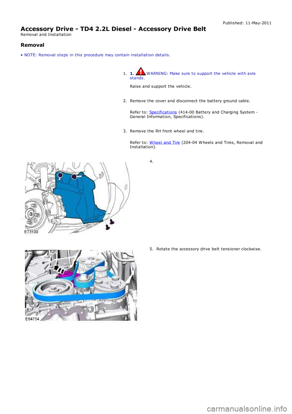
1. W ARNING: Make sure t o s upport the vehicle wit h axles tands .
Rais e and s upport t he vehi cl e.
1.
Remove t he cover and dis connect the bat tery ground cabl e.
Refer t o: Specificati ons (414-00 Bat tery and Charging Sys tem -General Informat ion, Specificati ons).
2.
Remove t he RH front wheel and t ire.
Refer t o: W heel and Ti re (204-04 W heel s and Tires, Removal andInst all at ion).
3.
4.
Rotat e t he acces sory dri ve belt t ens ioner clockwi s e.5.
Page 1073 of 3229
Publi s hed: 11-May-2011
Accessory Drive - TD4 2.2L Diesel - Accessory Drive Belt Tensioner
Removal and Inst all ati on
Removal
• NOTE: Removal s t eps in t his procedure may cont ain i nst all ati on det ail s.
Remove t he cover and dis connect the bat tery ground cabl e.
Refer t o: Specificati ons (414-00 Bat tery and Charging Sys tem -
General Informat ion, Specificati ons).
1.
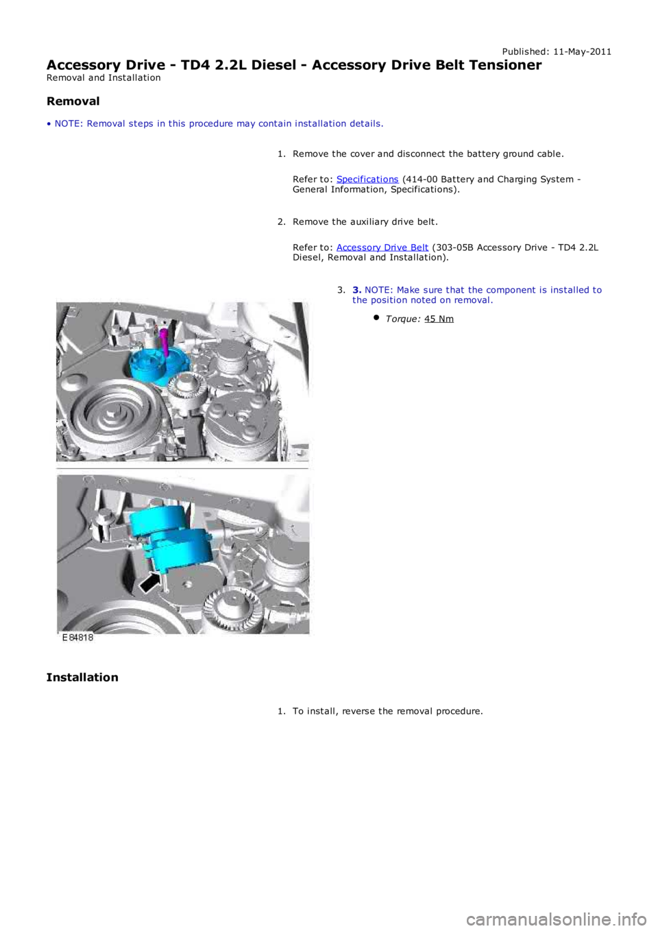
Remove t he auxi liary dri ve belt .
Refer t o: Acces sory Dri ve Belt (303-05B Acces sory Drive - TD4 2.2L
Di es el, Removal and Ins tal lat ion).
2. 3.
NOTE: Make s ure t hat the component i s ins t al led t o
t he posi ti on noted on removal .
T orque: 45 Nm 3.
Installation To i nst all , revers e t he removal procedure.
1.
Page 1074 of 3229
Publi s hed: 11-May-2011
Accessory Drive - TD4 2.2L Diesel - Accessory Drive Belt Idler Pulley
Removal and Inst all ati on
Removal
• NOTE: Removal s t eps in t his procedure may cont ain i nst all ati on det ail s.
Di sconnect t he bat t ery ground cable.
Refer t o: Specificati ons (414-00 Bat tery and Charging Sys tem -
General Informat ion, Specificati ons).
1.
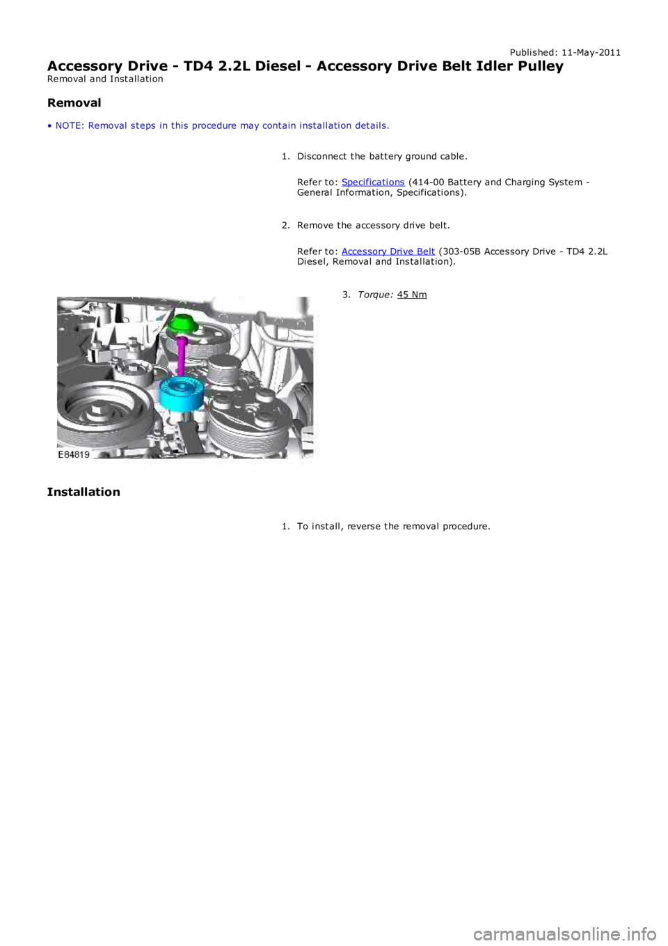
Remove t he acces sory dri ve bel t.
Refer t o: Acces sory Dri ve Belt (303-05B Acces sory Drive - TD4 2.2L
Di es el, Removal and Ins tal lat ion).
2. T orque:
45 Nm 3.
Installation To i nst all , revers e t he removal procedure.
1.
Page 1109 of 3229
Fuel fired heat er
The FFBH (fuel fired boost er heat er) and St op/Start s ys t em wi ll not operate si mult aneous ly, due to low ambientt emperatures bei ng a fact or in t he funct ion of both sys tems .
Hood Latch Ajar-Switch
W ARNING: To avoi d injury when performing repai r work on t he vehicle al ways di s abl e the Stop/St art s ys tem bypres s ing t he ‘ECO’ butt on, ens ure that ‘ECO STOP/START OFF’ is di s pl ayed in t he mes sage Cent er and the ECO tel l-taleli ght in t he s wit ch is ext inguis hed.
The hood lat ch ajar-s wit ch hardwired to the CJB, has two functi ons :
Acts as a s top i nhi bit or, all owing t he engi ne t o remai n running if t he hood latch i s rel eased.Deact ivates the St op/Start s ys t em i f an engi ne s top i s t aki ng place, t his res ul ts in an engine st all ed condit ion. Theengi ne can be res t art ed usi ng t he ignit ion but ton. Stal l recovery wil l not funct ion i n t hi s condi ti on; refer t o t he StallRecovery secti on.
Aft er the hood i s clos ed reacti vat ion of t he Stop/Start sys tem is achieved by manuall y s tarti ng the engine.
System Fault
The Stop/St art s ys tem is aut omati cal ly acti vat ed each ti me an ignit ion cycl e occurs; t he dri ver will be i nformed t he sys t emis operat ing by the t ell -t ale l ight in the Eco s wi tch i lluminati ng. If the tell -t ale light does not il luminat e t hi s wi ll indicat et hat t here i s eit her a s ys t em faul t or the sys tem is not avail abl e. Onl y when t he dri ver at tempt s t o act ivat e t he sys t em bypres s ing t he ‘Eco’ but ton will t hey be informed of a fault by ‘ECO STOP/START FAULT’ being di spl ayed i n t he mes sageCenter.
Owi ng to the St op/Start s ys t em’s complexit y due t o many ot her vehicle modul es and communicat ion net works i nvol ved i nit s funct ion. It i s recommended t hat al l ot her sys tem faul ts be init ial ly diagnos ed and eliminated when inves t igati ngStop/St art fault s as t hes e could affect the operat ion of t he St op/Start sys tem.
Syst em DTC (di agnos ti c troubl e code)can be diagnos ed us ing Land Rover approved di agnos ti c equi pment.
STOP INHIBITORS, START INITIATORS AND START INHIBITORS
A number of s el ect able feat ures or vehicle si tuat ions can infl uence t he operat ion of t he Stop/St art s yst em’s operati on.Thes e can, depending on the parti cular circumst ances :
prevent the engine s hutt ing down (s t op inhibi tor),ini ti at e an aut onomous res tart (s tart ini ti at or),prevent an engi ne res t art (st art i nhi bit or).
Stop Inhibitors
Under normal ci rcums tances the St op/St art s ys t em wi ll automat icall y s hut down t he engi ne if:
t he vehi cl e is st ati onary,t he trans mi s si on is in neutral,t he cl utch pedal i s ful ly releas ed.
The fol lowing condit ions wi ll inhibi t the engine from s hutt ing down:
Dri ver effected st op inhi bi tor
The fol lowing driver effect ed condi ti ons will i nhi bit t he engi ne from shut ti ng down:
Dri ver s wi tches off t he Stop/St art s ys temTrans mis s ion not i n neut ral((no te that the d rive r re sting their ha nd o n the g ea r le ve r ca n move the tra ns mis sion o ut o f the ne utra l w ind o w w itho ut e nga g ing a ge a r))
Clut ch pedal not full y rel easedAccelerator pedal depres s edHood is openDri ver’s door is openDri ver’s safet y belt i s dis engagedHDC (hil l decent cont rol) i s acti veTR (terrain res pons e) mode i s act iveCli mate cont rol s ys t em us ed above cal ibrat ed thresholdW i nds hiel d demis t i s operati ngTrai ler electrical connect ion det ect ed
Vehicle s ys tem effect ed s top i nhi bit or
The fol lowing vehicl e s ys t em condi ti ons wil l inhibit t he engine from s hut ti ng down:
Dri ver s wi tches off t he Stop/St art s ys temBrake s ervo vacuum below thres holdBatt ery cold cranki ng capabil it y below t hres holdBatt ery s t ate of charge i s lowCatal yt ic converter out si de eit her pre or post cali brati on rangeDPF (di esel part iculat e filt er) i s regenerat ingEngi ne cool ant temperat ure bel ow t hreshol dEngi ne oil t emperature below thres hold
Page 1110 of 3229
Envi ronmental effected s t op inhibi tor
The fol lowing environmental condit ions wi ll i nhi bit t he engi ne from s hutt ing down:
External t emperature above 35°CExternal t emperature below 4°C
Start Initiators
W hen t he engine has s hutdown wi thi n a St op/Start cycle the followi ng condi ti ons will i nit iate an early res tart wit hin t hes ame St op/Start cycle:
Dri ver effected st art i nit iator
The fol lowing driver effect ed condi ti ons will i nit iate an earl y engi ne res t art:
Dri ver s wi tches off t he Stop/St art s ys temVehicle s peed above cali brat ed threshold 3 Km/hour (2 mi le/hour)- A res tart will only occur if t he transmis s ion i s in neut ral and the driver’s pres ence is det ect ed for example, thedri ver’s s afet y belt remains s ecured and t he driver’s door remains latchedBrake s ervo vacuum below thres hold (dri ver operat ing brake pedal)HDC (hil l decent cont rol) i s acti vat edTR (terrain res pons e) mode i s act ivat edA hi gher heater fan speed i s s elect edW i nds hiel d demis t i s act ivat ed
Vehicle s ys tem effect ed s tart init iat or
The fol lowing vehicl e s ys t em condi ti ons wil l init iat e an earl y engine res t art :
Batt ery cranking capabili ty is near it s l ower t hres hol dBatt ery s t ate of charge i s near it s lower t hreshol dW i nds hiel d demis t acti vat esThe int eri or cabin t emperat ure decreas es bel ow or increas es above the occupant’s s et thres holds
Envi ronmental effected s t art ini ti ator
The fol lowing environmental condit ions wi ll i ni ti ate an early engi ne res tart:
External t emperature ri s es above 35°CExternal t emperature reduces bel ow 4°C
Start Inhibitors
W hen t he engine has s hutdown wi thi n a St op/Start cycle the followi ng condi ti ons will prevent an automat ic res tart :
Dri ver effected st art i nhi bit or
The fol lowing driver effect ed condi ti ons will i nhi bit an aut omati c engi ne res tart:
Hood has been openedThe accelerator pedal i s depress edGear sel ect or moved out of neutral; mes s age Cent er wil l di spl ay: ‘Sel ect Neut ral To Res tart ’Dri ver’s safet y belt i s dis engaged; t hi s i s an automat ic s t art inhi bi tor t herefore the engi ne can be res tarted bydepres si ng the cl utch pedalDri ver’s door is unl atched; t his is an aut omati c st art i nhibit or therefore t he engine can be rest art ed by depres si ngt he cl utch pedal
Vehicle s ys tem effect ed s tart inhibit or
The fol lowing vehicl e s ys t em condi ti ons wil l inhibit an aut omati c engi ne res t art :
Engi ne has s hut down for l onger t han 5 mi nut es : a conventi onal res t art wi ll be requi redThere i s a s ys tem fault
Page 1629 of 3229
Publi shed: 06-Jul-2011
Climate Control System - General Information - Climate Control System
Diagnosi s and Tes ti ng
Principles of Operation
For a detail ed descripti on of the cl imat e cont rol s yst em, refer to the relevant Des cri pti on and Operati on s ect ion i n t heworks hop manual . REFER to:
Air Dis t ri but ion and Fi lt ering (412-01 Cl imat e Control, Des cript ion and Operat ion),Heat ing and Vent il at ion (412-01 Cl imat e Control, Des cript ion and Operat ion),Air Condi ti oning (412-01 Cli mate Cont rol , Des cri pti on and Operati on),Cont rol Component s (412-01 Cli mate Cont rol , Des cri pti on and Operati on),Elect ric Boost er Heater (412-02B Auxi liary Cli mate Cont rol , Descri pti on and Operat ion),Fuel Fired Boos t er Heat er (412-02B Auxil iary Cli mate Cont rol, Des cri pt ion and Operati on).
Inspection and Verification
CAUTION: Di agnos is by s ubs ti tut ion from a donor vehicle is NO T acceptabl e. Subs ti tut ion of cont rol modules doesnot guarant ee confirmat ion of a faul t, and may als o caus e addit ional fault s i n t he vehi cl e being t est ed and/or t he donorvehi cl e.
1. Verify t he cus t omer concern.1.
2. Vis ually ins pect for obvious s igns of damage and s ys t em i ntegri ty.2.
Visual InspectionMechanicalElectrical
Coolant levelRefrigerant l eaks (UV l amp)Drive beltCompres s orCooli ng fanControl flap(s)Duct(s )Regis ter(s )Cabin ai r fi lt erHos e(s )Coolant pumpFuel Fi red Boos ter HeaterFuel Fi red Boos ter Heater fuel pumpFuel Fi red Boos ter Heater fuel pipes
Fus e(s)Circui tBlower mot orElectrical connect or(s)Compres s orCool ing fanAct uatorsCli mate cont rol ass embly
3. Lis ten for any unus ual noi ses during cli mate cont rol s ys t em operat ion.3.
4. Ins pect t he refri gerant s ys t em wi th an ult raviolet (UV) lamp for t races of UV s ens i ti ve leak t race dye.4.
5. If an obvious cause for an obs erved or report ed concern is found, correct t he caus e (if pos s ible) beforeproceeding t o t he next s t ep5.
6. If t he caus e is not vis ually evi dent , check Cli mate Cont rol Module, Engi ne Control Module (ECM), Fuel FiredBoos ter Heater and Central Juncti on Box (CJB) for Di agnos ti c Trouble Codes (DTCs ) and refer to the DTC Index.6.
Climate Control System
• NOTE: If a cont rol module or component i s s uspect and the vehicl e remai ns under manufacturer warrant y, refer t o t heW arranty Pol icy and Procedures manual (s ect ion B1.2), or determine i f any pri or approval program is i n operat ion, beforet he replacement of a component.
• NOTE: Generic scan t ool s may not read the codes li st ed, or may read only 5-digi t codes . Match t he 5 digi ts from t he s cant ool t o t he fi rs t 5 di gi ts of the 7-digit code li s ted t o i dent ify the fault (the last 2 digi ts gi ve ext ra informati on read by themanufacturer-approved di agnos ti c s ys t em).
• NOTE: W hen performing volt age or res is t ance t est s , always use a digi tal mult imeter (DMM) accurat e t o t hree deci malplaces, and wi th an up-t o-date cal ibrat ion cert ificate. W hen tes ti ng res is t ance al ways take t he res is t ance of t he DMMleads i nt o account .
• NOTE: Check and recti fy bas ic faul ts before beginni ng diagnos t ic rout ines i nvol vi ng pinpoint t es t s.
• NOTE: Ins pect connect ors for s igns of water ingres s , and pins for damage and/or corros ion.
• NOTE: If DTCs are recorded and, aft er performi ng the pi npoi nt tes ts , a fault is not present , an int ermi tt ent concern maybe t he caus e. Always check for loose connect ions and corroded terminals .
Cli mate Cont rol Syst em
For a compl ete lis t of all Di agnos ti c Trouble Codes (DTCs) t hat could be logged on this vehicle, pleas e refer to Sect ion100-00.
REFER to: Di agnos ti c Trouble Code (DTC) Index - DTC: Heati ng Vent il ati on and Air Condit ioning Control Modul e (HVAC)(100-00 General Informati on, Des cri pti on and Operati on).
Page 1639 of 3229
int ernal components of t he A/C compres sor.
Alt hough di fferent unit s, t he A/C compres sors fi tt ed t o both the i 6 petrol engi ne and the TD4 dies el engine are bothvariabl e dis placement uni ts . The dis placement (flow of refrigerant) i s cont rol led t o mat ch t he thermal l oad of theevaporat or.
Operat ion of t he A/C sys t em i s cont roll ed by t he Automat ic Temperat ure Cont rol (ATC) module.For addit ional informat ion, refer t o: Cont rol Component s (412-01 Cli mat e Cont rol , Descripti on and Operat ion).
A/C COMPRESSOR
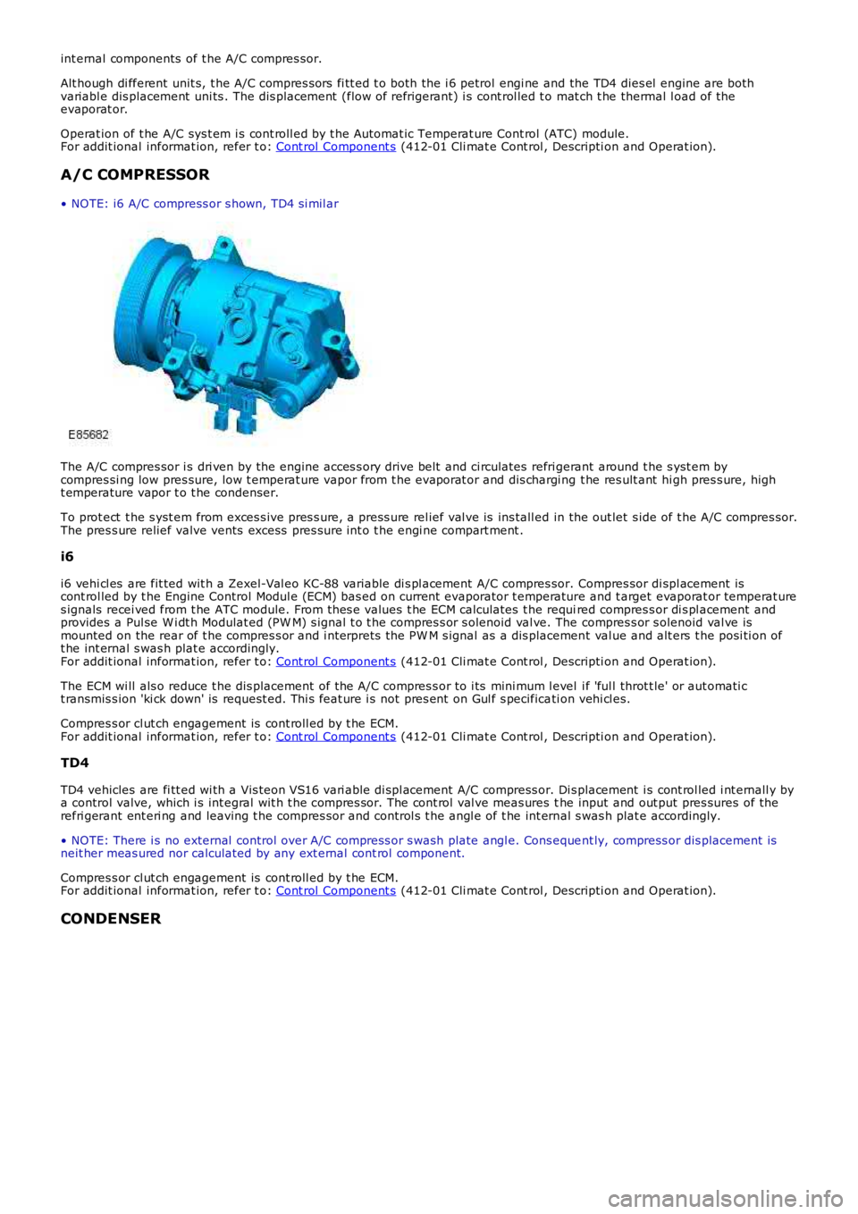
• NOTE: i6 A/C compress or s hown, TD4 s i mil ar
The A/C compres sor i s dri ven by the engine acces s ory drive belt and ci rculates refrigerant around t he s yst em bycompres si ng low pres sure, low t emperat ure vapor from t he evaporat or and dis chargi ng t he res ult ant hi gh pres s ure, hight emperature vapor t o t he condenser.
To prot ect t he s yst em from exces s ive pres s ure, a press ure rel ief val ve is ins tall ed in the out let s ide of t he A/C compres sor.The pres s ure relief valve vents excess pres sure int o t he engi ne compart ment .
i6
i6 vehi cl es are fit ted wit h a Zexel-Val eo KC-88 variable di s pl acement A/C compres sor. Compres sor di spl acement iscont rol led by t he Engine Control Modul e (ECM) bas ed on current evaporator t emperature and t arget evaporat or temperat ures ignals recei ved from t he ATC module. From thes e values t he ECM calculates t he required compres s or di s pl acement andprovides a Pul se W i dt h Modulat ed (PW M) s ignal t o t he compres s or s olenoid val ve. The compres s or s olenoid val ve ismounted on the rear of t he compres s or and i nterprets the PW M s ignal as a dis placement val ue and alt ers t he posi ti on oft he int ernal s was h plat e accordingly.For addit ional informat ion, refer t o: Cont rol Component s (412-01 Cli mat e Cont rol , Descripti on and Operat ion).
The ECM wi ll als o reduce t he dis placement of the A/C compres s or to i ts mini mum l evel i f 'ful l throt t le' or aut omati ct ransmis s ion 'ki ck down' is request ed. Thi s feat ure i s not pres ent on Gul f s pecificati on vehi cl es.
Compres s or cl ut ch engagement is cont roll ed by t he ECM.For addit ional informat ion, refer t o: Cont rol Component s (412-01 Cli mat e Cont rol , Descripti on and Operat ion).
TD4
TD4 vehicles are fi tt ed wi th a Vis teon VS16 vari able di spl acement A/C compress or. Dis placement i s cont rol led i nt ernall y bya control valve, which i s int egral wit h t he compres sor. The cont rol val ve meas ures the input and out put pres sures of therefri gerant ent eri ng and leaving t he compres sor and control s t he angl e of t he int ernal s was h plat e accordingly.
• NOTE: There i s no external control over A/C compress or s wash plate angl e. Cons equent ly, compress or dis placement isneit her meas ured nor calculated by any ext ernal cont rol component.
Compres s or cl ut ch engagement is cont roll ed by t he ECM.For addit ional informat ion, refer t o: Cont rol Component s (412-01 Cli mat e Cont rol , Descripti on and Operat ion).
CONDENSER