2006 LAND ROVER FRELANDER 2 belt
[x] Cancel search: beltPage 1712 of 3229
Publi s hed: 11-May-2011
Climate Control - Air Conditioning (A/C) CompressorI6 3.2L Petrol
Removal and Inst all ati on
Removal
CAUTION: Make s ure that the specified amount of refrigerant oi l is added.
Remove t he cover and dis connect the bat tery ground cabl e.
Refer t o: Specificati ons (414-00 Bat tery and Charging Sys tem -General Informat ion, Specificati ons).
1.
Recover t he air condi ti oni ng (A/C) refri gerant .
Refer t o: Air Condi ti oning (A/C) Sys tem Recovery, Evacuati on andCharging (412-00 Cl imat e Control Sys t em - General Informat ion,General Procedures).
2.
Remove t he engi ne cover.
Refer t o: Engi ne Cover - I6 3.2L Pet rol (501-05 Int eri or Trim andOrnament ati on, Removal and Ins tal lat ion).
3.
Remove t he bat t ery t ray.
Refer t o: Bat t ery Tray (414-01 Bat tery, Mount ing and Cables ,Removal and Ins tall ati on).
4.
Remove t he air cleaner as s embly.
Refer t o: Air Cleaner (303-12A Intake Ai r Dis tribut ion and Fil tering -I6 3.2L Pet rol, Removal and Ins t al lat ion).
5.
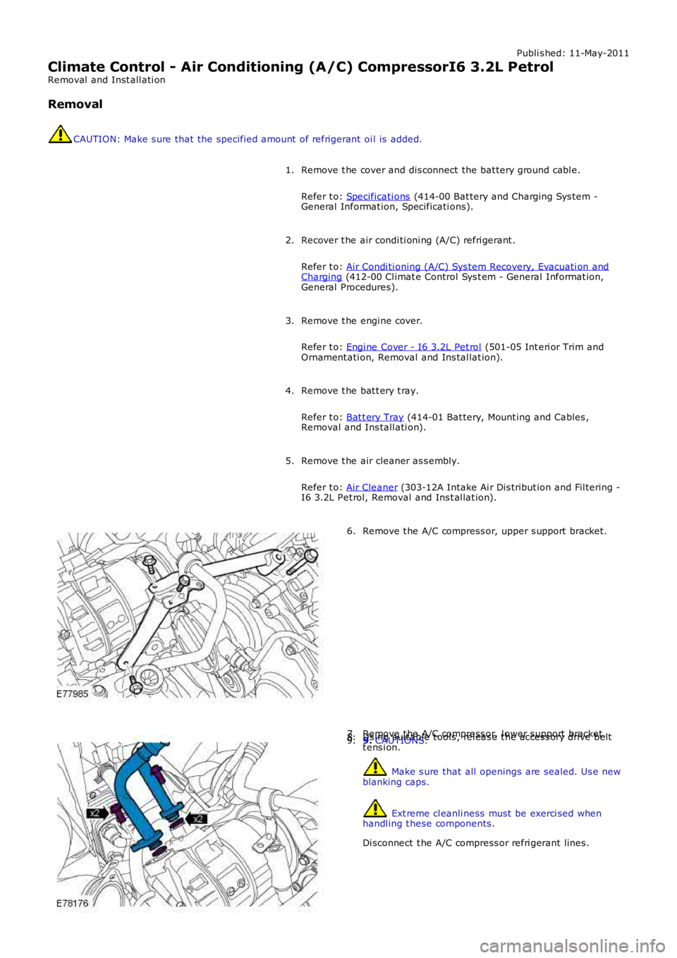
Remove t he A/C compress or, upper s upport bracket.6.
Remove t he A/C compress or, l ower support bracket.7.Us ing s uit able t ools , rel eas e t he acces s ory drive beltt ens i on.8.9. CAUTIONS:
Make s ure that all openings are sealed. Us e newblanking caps.
Ext reme cl eanli ness must be exerci sed whenhandl ing t hese components .
Di sconnect t he A/C compress or refri gerant lines .
9.
Page 1752 of 3229
12-Fuel fi red boos ter heat er
13-FFBH/DAB ant enna (Vehicles from 2009MY )
14-Fus e 32, BJB15-Fus e FA5, RJB
16-FFBH Remot e hands et (Vehi cl es from 2009MY )
PRINCIPLES OF OPERATION
If a heat ing reques t i s received and t he ambient air t emperature is les s t han or equal to 5°C (41 °F), t he ATC modulet ransmit s a 'supplement al heat' mes s age to the FFBH control modul e over the medi um speed CAN bus . The control modul eres ponds by ret urning a 's uppl ement al heat ' st atus mess age back to the ATC modul e. The control modul e wi ll now i nit iatet he FFBH st art s equence.
If the heati ng reques t is removed, or ambient air t emperat ure ris es t o 8°C (46 °F), the ATC modul e t rans mit s a 'heat er off'mes s age to t he FFBH cont rol module over t he medium s peed CAN bus . Again, t he cont rol module res ponds by returni ng a'heater off' s tat us mes sage back to the ATC modul e. The cont rol module wi ll now de-act ivate the FFBH.
If maxi mum heat ing i s reques ted, Engi ne Cool ant Temperature (ECT) becomes the overriding factor. In t his i nst ance, t heATC module wil l change the CAN bus mes sage from 'heater off' to 's uppl emental heat ' when ECT is bel ow or equal t o 70°C(158°F). If ECT ri ses to 78°C (172°F) t he ATC module returns the mess age t o 'heater off'.
The cont rol module wil l not s t art t he FFBH, or wil l dis cont inue operat ion, if any of the foll owing occur:
The cont rol module is i n t he error l ockout mode (see Diagnostics, below).The engi ne is not runni ng, or s t ops running for approxi mately 4 s econds . The ti me delay i s included for s t alldetecti on.A 'fuel cut -off' mes s age is recei ved from t he CJB over t he medium s peed CAN bus .For addit ional informat ion, refer t o: Air Bag and Safet y Belt Pretens ioner Supplement al Res traint Syst em (SRS)(501-20B Supplement al Res t raint Sys tem, Des cript ion and O perati on).A l ow fuel l evel mes s age is recei ved from t he CJB over t he medium s peed CAN bus (s ee t abl e below).For addit ional informat ion, refer t o: Ins t rument Clus ter (413-01 Inst rument Cl us t er, Des cript ion and Operat ion).
The cont rol module wil l control FFBH operat ion bas ed on t he fol lowi ng levels of fuel i n the tank.
Fuel Level, liters (US Gallons)Description
7.5 (1.98)St art
4.5 (1.18)St op10.5 (2.77)Res tart
Start Sequence
At t he begi nni ng of a s tart s equence, t he FFBH cont rol module;
energizes t he glow pi n and flame s ens or t o pre heat the combust ion chambers tarts t he combust ion ai r fan at s l ow s peedand energizes t he auxi liary cool ant pump.
Aft er approxi matel y 30 s econds , the control modul e energizes t he auxi li ary fuel pump at t he s tarti ng s equence s peed. Thefuel deli vered by the auxil iary fuel pump evaporates i n t he combus t ion chamber, mi xes wi th air from the combus ti on air fanand is ignit ed by t he glow pi n and fl ame s ensor. The cont rol module t hen progres s ively increases t he s peed of the auxil iaryfuel pump and t he combus t ion ai r fan. Once combus ti on is est ablis hed t he cont rol module swi tches t he glow pi n and fl ames ens or t o the fl ame s ens i ng functi on to monit or combus ti on. From t he begi nni ng of the st art s equence t o s tabl ecombus t ion at full load t akes approxi mately 150 seconds .
Full and Part Load Combustion
W hi le t he FFBH is running, the control modul e cycl es the heat er bet ween ful l l oad combus t ion, part load combus ti on and acont rol i dl e phase of operat ion, depending on the temperat ure of t he cool ant in t he heat exchanger.
The heat out put level at part l oad combus t ion i s 2.8 kW . Thi s ris es to 5 kW at full l oad combus ti on. The control modul et ransmit s t he amount of fuel us ed by t he FFBH to the i nst rument clus t er, and t he FFBH coolant t emperature t o t he ATCmodule.
Swit chi ng Point Temperatures
Page 1770 of 3229
23-Transmis s ion warni ng indi cat or (low li ne only)
24-Hil l Des cent Cont rol (HDC) fault i ndi cat or (l ow li ne only)
25-Door open i ndi cat or (l ow li ne only)26-Engi ne management s yst em warning i ndicat or (l ow l ine only)
27-Side l amp indicat or
28-Dynami c Stabil it y Control (DSC) indicat or29-HDC acti ve indicator
30-Ant i-t heft alarm i ndi cat or
31-Glow pl ug indicat or (dies el vehicles onl y)32-Fuel fired boos ter heater i ndi cat or (i f fi tt ed)
The low li ne ins trument cl ust er cont ains 39 i ndi cat ors , the hi gh li ne ins t rument clus ter 27. The indicators in hi gh li neins t rument clus ters are s upplemented by mess ages in the mess age cent er.For addit ional informat ion, refer t o: Informat ion and Mes s age Cent er (413-08 Informat ion and Mes s age Cent er, Des cript ionand Operat ion).
The warni ng indicators can be s plit i nto 2 groups ; sel f cont roll ed and ext ernall y cont rol led. Self cont rol led warni ngindicat ors are dependent on software l ogi c wit hin t he i ns t rument clus ter for act ivati on. External ly controll ed indicators ares uppl ied wi th current from anot her s yst em cont roll ing module or ill uminat ed by the ins trument cl us t er on receipt of amedium s peed CAN bus mes sage from the CJB.
Ignition/No Charge Indicator
The ignit ion/no charge indicator i s cont rol led by t he ins t rument clus ter s oft ware and i ll uminated by medium speed CAN buss ignals from the ECM via t he CJB. The indicator il lumi nat es i n a red col or when the vehicle ent ers power mode 6 and isexti nguis hed when t he engine i s s tart ed.
If the i ndi cat or remai ns ill uminat ed aft er the engine has s t art ed or ill uminat es when drivi ng, t he alt ernator charge out puthas fai led.
Low Oil Pressure Warning Indicator
The low oil pres s ure warning i ndi cat or is i lluminated by t he i ns t rument clus ter on recei pt of a medium speed CAN buss ignal from t he CJB. The s ignal ori gi nates i n t he ECM and is generat ed by t he engi ne oil l evel s ens or on petrol vehicl es andt he engi ne oil pres s ure s ensor on di esel vehi cles .
The indicat or i ll uminates i n a red color when t he vehi cl e enters power mode 6 for a 3 s econd bulb check. If t he bul bs ubs equent ly ill uminat es when the engine is runni ng, t he engine s houl d be s t opped i mmediat ely i t is s afe to do s o.
Malfunction Indicator Lamp
The Malfunct ion Indicat or Lamp (MIL) i s il lumi nat ed by t he ins trument cl ust er on receipt of a medi um s peed CAN bus s ignalfrom the CJB. The si gnal originat es in t he ECM and i s generated if an On-Board Diagnos ti c (OBD) fault has been det ectedwhich wi ll caus e excess i ve emis s ions output. Thi s may rel ate to ei ther an engine management or trans mi ss i on fault .
The MIL is ill uminat ed in an amber color when t he vehi cl e enters power mode 6 for a 3 s econd bul b check. The bul b checkin thi s ins tance is carri ed out by the ECM vi a t he CJB, not t he ins trument cl ust er. If t he MIL subs equent ly i lluminates t hevehi cl e s houl d be i nterrogated us ing t he Land Rover approved diagnost ic sys tem at the earli es t opport uni ty.
Safety Belt Warning Indicator
The s afety bel t warni ng indicator wi ll il lumi nat e i n a red color on receipt of a medi um s peed CAN bus s ignal from t he CJB.The s ignal origi nat es in the Res traint s Cont rol Module (RCM), which monit ors the s t at us of t he occupant clas s ificati ons ys t em and s wi tches located i n t he s afety bel t buckles .
Three vari ati ons of warning are avai lable depending on vehicle confi gurati on:
Reminder (al l vehicl es except Nort h Ameri can Specificati on (NAS) vehicles )Federal Mot or Vehi cl e Safet y Standard (FMVSS) 208 remi nder (NAS vehi cles only)Belt Mi nder
The condi ti ons for s afety bel t warning indicator il lumi nat ion are as follows :
Reminder
Vehicle i n power mode 6Dri vers s afet y belt not s ecured in i ts buckleLarge pas senger det ect ed i n front pas s enger s eat wit h an uns ecured safety bel t.
The warni ng indicator wi ll remai n i lluminated unt il eit her t he i gni ti on is swi tched off or condi ti ons 2 and 3 no longer exis t .
FMVSS-208 Reminder
Vehicle i n power mode 6Dri vers s afet y belt not s ecured in i ts buckle.
The warni ng indicator wi ll remai n i lluminated for 65 s econds and wil l be accompanied by a si ngl e 6 second chi me from theins t rument clus ter s ounder.
• NOTE: The warni ng indicator and chime wil l not acti vat e i f thes e condi ti ons aris e 75 seconds aft er t he vehicle hasentered power mode 6.
The warni ng indicator wi ll be exti ngui shed and t he s ounder cancell ed if t he i gni ti on is s wi tched off or t he dri ver's s afet ybelt i s s ecured in i ts buckle.
Belt Mi nder
Page 1771 of 3229
Vehicle i n power mode 6 (all vehi cles except NAS vehicles )Vehicle i n power mode 6 for 75 s econds (NAS vehicl es onl y)Vehicle s peed is greater t han 6 mph (10 kph)Dri vers s afet y belt not s ecured in i ts buckleLarge pas senger det ect ed i n front pas s enger s eat wit h an uns ecured safety bel t.
The warni ng indicator wi ll flas h at a frequency of 2 Hz while accompani ed by a chime from the i nst rument clus ter for 10s econds. Thi s is foll owed by a 10 s econd period where the warning i ndicat or is permanent ly ill uminat ed and the s ounder i ss il ent . Thi s 10 s econd cycle wi ll be repeat ed for a maxi mum of 190 seconds or any of t he condit ions l is t ed above cease toexis t.
Supplemental Restraint System Warning Indicator
The Suppl ement al Rest rai nt Sys tem (SRS) warning i ndi cat or is i lluminated on recei pt of a medium s peed CAN bus si gnalfrom the CJB. The si gnal originat es in t he RCM whi ch monit ors t he condi ti on of the SRS and ill uminat es the red warni ngindicat or accordingly.
The SRS warni ng indicator i s il lumi nat ed by t he RCM for a 6 s econd bul b check when the vehicle firs t ent ers power mode 6.If a fault is detect ed wit h t he indicator, the ins trument cl us t er returns a medi um speed CAN bus s ignal vi a t he CJB to theRCM and a Diagnos t ic Troubl e Code (DTC) i s s tored in the RCM's memory. The mes s age 'SrS' wi ll als o be di spl ayed i n t heodometer.For addit ional informat ion, refer t o: Informat ion and Mes s age Cent er (413-08 Informat ion and Mes s age Cent er, Des cript ionand Operat ion).
Left and Right Hand Turn Signal Indicators
The green l eft and right hand turn s ignal i ndicat ors are i ll uminated on recei pt of medium speed CAN bus s i gnals from t heCJB. The CJB provi des a CAN bus s ignal wit h one of t he foll owing values :
0 - LH st eeri ng col umn mul ti -funct ion s wit ch in the central pos it ion1 - LH st eeri ng col umn mul ti -funct ion s wit ch in the LH turn posi ti on2 - LH st eeri ng col umn mul ti -funct ion s wit ch in the RH turn pos it ion3 - Hazard fl as hers reques t ed.
If the vehicle is i n power mode 6 t he ins trument cl ust er wil l fl as h the appropri ate turn s ignal i ndicat or if a medium speedCAN bus s ignal is recei ved wit h a value of 1 or 2. Medi um s peed CAN bus s ignals wi th a value of 3 wi ll acti vat e both theLH and RH turn s ignal i ndicat ors si mult aneous ly i rrespecti ve of power mode.
W hen acti vat ed, the l eft and right hand turn s ignal indicators wil l be accompanied by 'ti ck t ock' chimes from t he ins trumentclus ter s ounder.
Brake Warning Indicator
EBA and EBD warnings are trans mi tt ed t o t he CJB from t he ABS module over t he high s peed CAN bus . Thes e s ignals arerel ayed t o t he i ns t rument clus ter on t he medium s peed CAN bus and wil l act ivate the brake warning i ndicat or when t hevehi cl e i s in power mode 6. If an EBA warni ng is request ed, the i ndi cat or wil l ill uminat e in an amber color. If an EBDwarni ng is reques t ed, t he indi cat or will i ll uminate in a red color.
Low brake flui d level warnings are als o t rans mit t ed to the i nst rument clus t er from the CJB on the medi um s peed CAN bus .The s ignal origi nat es in the ABS modul e which recei ves a hardwired input from the brake flui d level s ens or. If a l ow brakefl uid warning i s reques ted, the indicator wil l il lumi nat e i n a red col or when the vehicle is i n power mode 6.
The brake warni ng indi cat or i s als o s ubject t o a 3 second bul b check when the vehicle firs t ent ers power mode 6. Theindicat or wi ll i lluminate in a amber color for 1.5 s econds t hen a red col or for 1.5 s econds .
High Eng ine Coolant Temperature Warning Ind icator
The red hi gh Engine Coolant Temperature (ECT) warning i ndi cat or is control led by the engine t emperat ure gage s oft ware(see above).
Headlamp High Beam Indicator
The blue headlamp hi gh beam i ndi cat or is i ll uminated on recei pt of a medium s peed CAN bus si gnal from the CJB. Thes ignal origi nat es in the l ight s wit ch module and i s t ransmit ted t o t he CJB over t he LIN bus. The i nst rument clus t er will onlyil lumi nat e t he headl amp high beam indicator when t he vehicle i s in power mode 6 and t he LH s teeri ng column mul ti -functi on s wit ch is moved t o t he high beam pos i ti on.
Tire Pressure Monitoring System Indicator
The Tire Pres s ure Moni tori ng Syst em (TPMS) indicator i s cont rol led by t he ins t rument clus ter on receipt of medium s peedCAN bus s ignals from t he CJB. The s ignal ori gi nates i n t he TPMS module. The indicator i s il lumi nat ed in an amber col or fora 3 second bulb check by the TPMS modul e when t he vehi cl e enters power mode 6. If t he indicator remains i lluminated orfl ashes after t he engi ne is st art ed or when dri vi ng, the TPMS has developed a faul t. The t ire pres s ures s houl d bemonit ored manuall y unti l the fault is recti fi ed.For addit ional informat ion, refer t o: W heels and Ti res (204-04 W heels and Tires , Des cript ion and Operat ion).
Anti-lock Brake System Warning Indicator
The Anti -l ock Brake Sys t em (ABS) warning i ndicat or is controll ed by the ABS module whi ch trans mi ts a high s peed CAN busmes s age to t he CJB. The CJB relays t he mes sage t o t he i ns t rument clus ter over the medi um s peed CAN bus . The warningindicat or i s il lumi nat ed i n an amber col or for 3 s econds for a bulb check by the ABS modul e when t he vehi cl e enters powermode 6. If the warning i ndi cat or remains ill uminat ed or ill uminat es when drivi ng, an ABS fault has occurred and t he ABSfuncti on wil l not be avai lable.
Duri ng the bul b check, if t he warni ng indicator comes on for 0.5 s econd, t hen goes off for 0.5 second and is then
Page 1822 of 3229
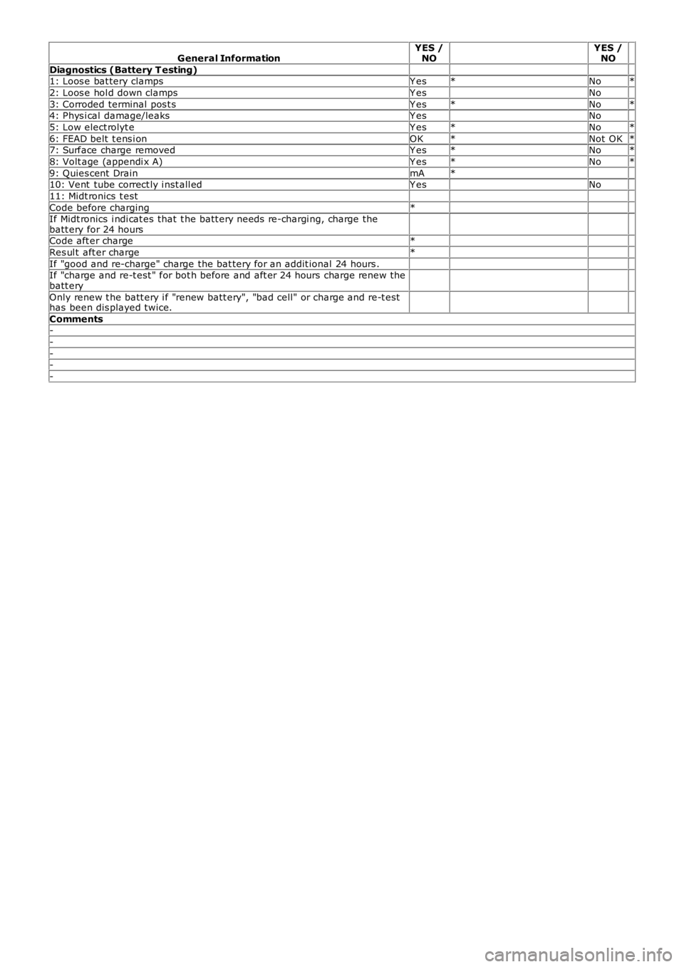
General InformationYES /NO YES /NO
Diagnostics (Battery T esting) 1: Loos e bat tery clampsY es*No*
2: Loos e hol d down clampsY es No
3: Corroded terminal pos t sY es*No*4: Phys i cal damage/leaksY es No
5: Low elect rolyt eY es*No*
6: FEAD belt t ens i onOK*Not OK*7: Surface charge removedY es*No*
8: Volt age (appendi x A)Y es*No*
9: Quies cent DrainmA* 10: Vent tube correct ly i nst all edY es No
11: Midt ronics t est
Code before charging* If Midt ronics i ndi cat es that t he batt ery needs re-chargi ng, charge thebatt ery for 24 hours
Code aft er charge*
Res ul t aft er charge*
If "good and re-charge" charge the bat tery for an addit ional 24 hours . If "charge and re-t est " for bot h before and aft er 24 hours charge renew thebatt ery
Only renew t he batt ery i f "renew batt ery", "bad cell" or charge and re-t esthas been dis played twice.
Comments-
-
--
-
Page 1824 of 3229
Publ is hed: 05-Dec-2011
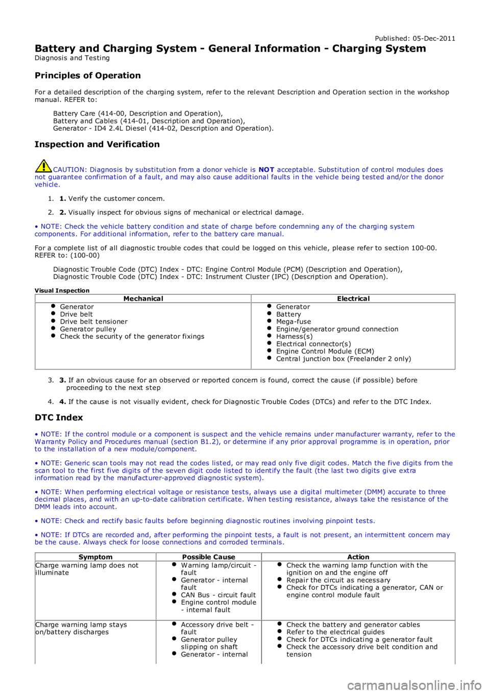
Battery and Charging System - General Information - Charging System
Diagnosi s and Tes ti ng
Principles of Operation
For a detail ed descripti on of the chargi ng s ys t em, refer t o t he rel evant Des cript ion and Operat ion secti on in the workshopmanual. REFER to:
Bat t ery Care (414-00, Des cript ion and Operat ion),Bat t ery and Cables (414-01, Des cri pti on and Operati on),Generator - ID4 2.4L Di esel (414-02, Des cri pt ion and Operati on).
Inspection and Verification
CAUTION: Di agnos is by s ubs ti tut ion from a donor vehicle is NO T acceptabl e. Subs ti tut ion of cont rol modules doesnot guarant ee confirmat ion of a faul t, and may als o caus e addit ional fault s i n t he vehi cl e being t est ed and/or t he donorvehi cl e.
1. Verify t he cus t omer concern.1.
2. Vis ually ins pect for obvious s igns of mechani cal or electrical damage.2.
• NOTE: Check the vehicle bat tery condi ti on and st ate of charge before condemning any of the chargi ng s ys t emcomponents . For addi ti onal i nformat ion, refer to the bat tery care manual.
For a compl ete lis t of all di agnos ti c troubl e codes that coul d be l ogged on t his vehicle, pleas e refer to s ect ion 100-00.REFER to: (100-00)
Diagnos t ic Troubl e Code (DTC) Index - DTC: Engine Cont rol Module (PCM) (Des cri pt ion and Operati on),Diagnos t ic Troubl e Code (DTC) Index - DTC: Ins trument Clus ter (IPC) (Des cri pti on and Operati on).
Visual Inspection
MechanicalElectricalGenerat orDrive beltDrive belt t ensi onerGenerat or pull eyCheck the s ecurit y of t he generat or fi xings
Generat orBat teryMega-fus eEngine/generat or ground connecti onHarness (s)El ect ri cal connector(s )Engine Cont rol Module (ECM)Cent ral juncti on box (Freel ander 2 onl y)
3. If an obvious cause for an obs erved or report ed concern is found, correct t he caus e (if pos s ible) beforeproceeding t o t he next s t ep3.
4. If t he caus e is not vis ually evi dent , check for Di agnos ti c Trouble Codes (DTCs) and refer t o t he DTC Index.4.
DTC Index
• NOTE: If the control modul e or a component i s s us pect and the vehicle remains under manufacturer warrant y, refer t o theW arranty Pol icy and Procedures manual (s ect ion B1.2), or determine i f any pri or approval programme is in operat ion, pri ort o the ins tall ati on of a new module/component.
• NOTE: Generic scan t ool s may not read the codes li st ed, or may read only fi ve digit codes . Mat ch the five di git s from t hes can tool to the firs t fi ve di git s of the seven digi t code l is ted to ident ify t he faul t (t he las t t wo digi ts gi ve ext rainformat ion read by the manufact urer-approved diagnost ic s ys tem).
• NOTE: W hen performing el ect ri cal volt age or resi s tance tes t s, al ways us e a digit al mult imet er (DMM) accurate to threedeci mal places , and wi th an up-to-date cali brat ion cert ificate. W hen t es ti ng res is t ance, always take t he res i st ance of t heDMM leads int o account.
• NOTE: Check and recti fy bas ic faul ts before beginni ng diagnos t ic rout ines i nvol vi ng pinpoint t es t s.
• NOTE: If DTCs are recorded and, aft er performi ng the pi npoi nt tes ts , a fault is not present , an int ermi tt ent concern maybe t he caus e. Always check for loose connect ions and corroded terminals .
SymptomPossible CauseAction
Charge warning l amp does noti llumi nateW arning l amp/circui t -faul tGenerat or - internalfaul tCAN Bus - ci rcuit faul tEngine control modul e- i nternal faul t
Check t he warni ng lamp functi on wit h t heignit ion on and the engine offRepai r the ci rcuit as neces s aryCheck for DTCs indicati ng a generator, CAN orengi ne cont rol module fault
Charge warning l amp s tayson/bat tery dis chargesAcces s ory drive belt -faul tGenerat or pul leys li ppi ng on s haftGenerat or - internal
Check t he batt ery and generat or cablesRefer t o the el ect ri cal guidesCheck for DTCs indicati ng a generator faul tCheck t he acces s ory drive belt condi ti on andtens ion
Page 1825 of 3229
1
2
1
2
3
4
5
6
1
1
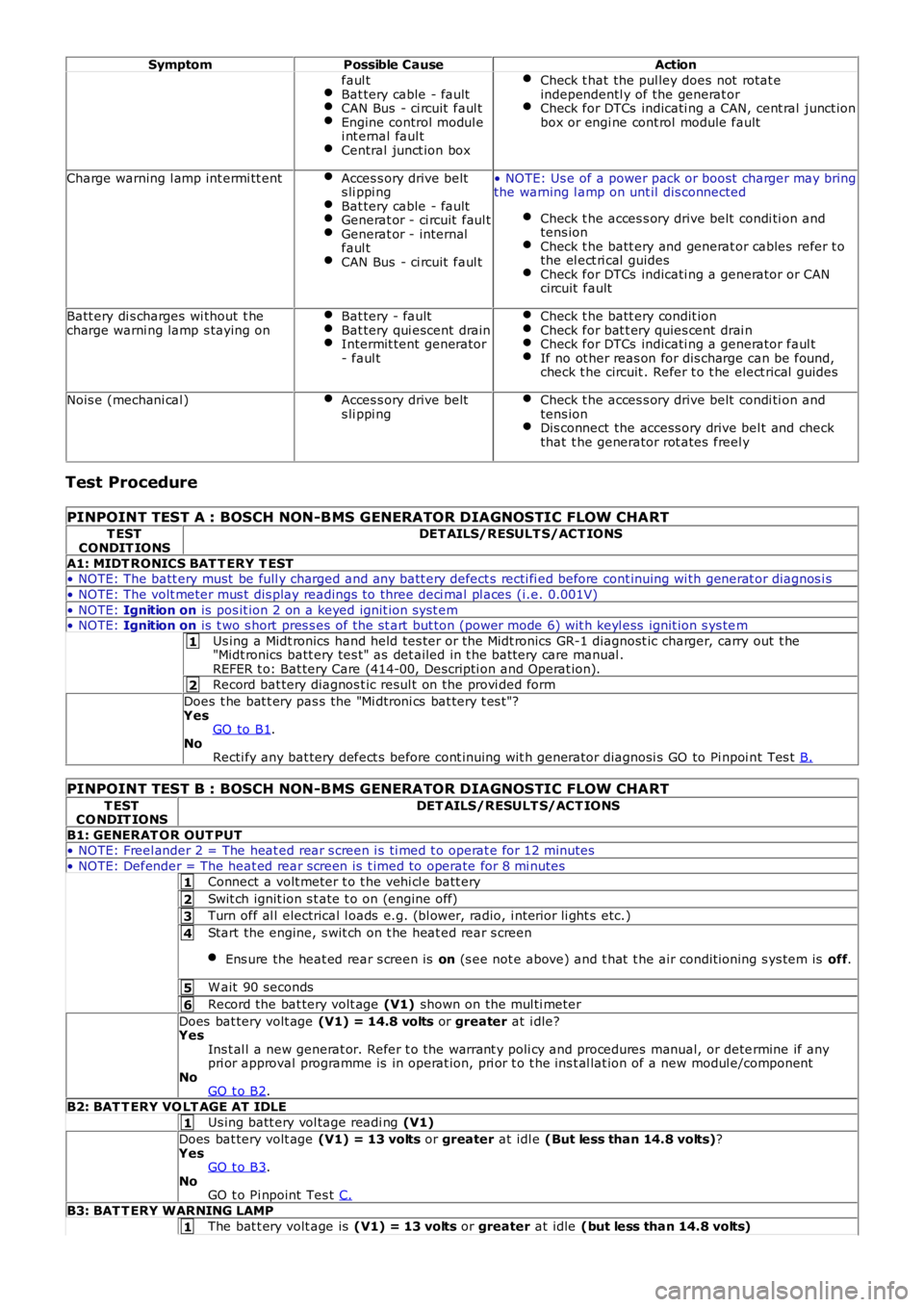
SymptomPossible CauseAction
faul tBat tery cable - faultCAN Bus - ci rcuit faul tEngine control modul ei nt ernal faul tCentral junct ion box
Check t hat the pul ley does not rotat eindependentl y of the generat orCheck for DTCs indicati ng a CAN, cent ral junct ionbox or engi ne cont rol module fault
Charge warning l amp int ermi tt entAcces s ory drive belts li ppi ngBat tery cable - faultGenerat or - ci rcuit faul tGenerat or - internalfaul tCAN Bus - ci rcuit faul t
• NOTE: Us e of a power pack or boost charger may bringthe warning l amp on unt il dis connected
Check t he acces s ory drive belt condi ti on andtens ionCheck t he batt ery and generat or cables refer t othe el ect ri cal guidesCheck for DTCs indicati ng a generator or CANcircuit fault
Batt ery di s charges wi thout t hecharge warni ng lamp s taying onBat tery - faultBat tery qui escent drainIntermit tent generator- faul t
Check t he batt ery condit ionCheck for bat t ery quies cent drai nCheck for DTCs indicati ng a generator faul tIf no ot her reas on for dis charge can be found,check t he circuit . Refer t o t he elect rical guides
Nois e (mechani cal )Acces s ory drive belts li ppi ngCheck t he acces s ory drive belt condi ti on andtens ionDis connect the access ory drive bel t and checkthat t he generator rot ates freel y
Test Procedure
PINPOINT TEST A : BOSCH NON-BMS GENERATOR DIAGNOSTIC FLOW CHART
T ESTCONDIT IONSDET AILS/RESULT S/ACT IONS
A1: MIDT RONICS BAT T ERY T EST• NOTE: The batt ery must be full y charged and any batt ery defect s recti fi ed before cont inuing wi th generat or diagnos i s
• NOTE: The volt meter mus t dis play readings to three deci mal pl aces (i.e. 0.001V)
• NOTE: Ignition on is pos it ion 2 on a keyed ignit ion s yst em• NOTE: Ignition on is t wo s hort pres s es of the st art but ton (power mode 6) wit h keyl ess ignit ion s ys tem
Us ing a Midt ronics hand held tes ter or t he Midt ronics GR-1 diagnost ic charger, carry out t he"Midt ronics batt ery tes t" as det ailed in t he batt ery care manual .REFER t o: Bat tery Care (414-00, Descripti on and Operat ion).
Record bat tery diagnos t ic resul t on the provi ded form
Does t he bat t ery pas s the "Mi dtroni cs bat tery t es t "?YesGO to B1.NoRecti fy any bat tery defect s before cont inuing wit h generator diagnosi s GO to Pi npoi nt Tes t B.
PINPOINT TEST B : BOSCH NON-BMS GENERATOR DIAGNOSTIC FLOW CHART
T ESTCO NDIT IONSDET AILS/RESULT S/ACT IONS
B1: GENERAT OR OUT PUT• NOTE: Freel ander 2 = The heat ed rear s creen i s ti med t o operat e for 12 minutes
• NOTE: Defender = The heat ed rear s creen is t imed to operate for 8 mi nutes
Connect a volt meter t o t he vehi cl e batt ery
Swit ch ignit ion s t ate t o on (engine off)
Turn off al l electrical l oads e.g. (bl ower, radio, i nteri or li ght s etc.)
Start the engine, s wit ch on t he heat ed rear s creen
Ens ure the heat ed rear s creen is on (s ee not e above) and t hat t he air condit ioning s ys tem is off.
W ait 90 seconds
Record the bat tery volt age (V1) shown on the mul ti meter
Does bat tery volt age (V1) = 14.8 volts or greater at i dle?YesIns t al l a new generat or. Refer t o the warrant y poli cy and procedures manual, or determine if anypri or approval programme is in operat ion, pri or t o t he ins t al lat ion of a new modul e/componentNoGO t o B2.
B2: BAT T ERY VO LT AGE AT IDLE
Us ing batt ery vol tage readi ng (V1)
Does bat tery volt age (V1) = 13 volts or greater at idl e (But less than 14.8 volts)?YesGO t o B3.NoGO t o Pi npoint Tes t C.
B3: BAT T ERY WARNING LAMP
The bat t ery volt age is (V1) = 13 volts or greater at idle (but less than 14.8 volts)
Page 1841 of 3229
Publi s hed: 11-May-2011
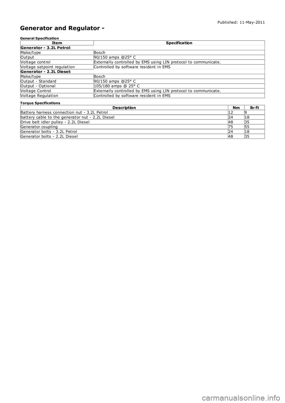
Generator and Regulator -
General SpecificationItemSpecification
Generator - 3.2L Petrol:
Make/t ypeBos chOut put90/150 amps @25° C
Volt age cont rolExternal ly controlled by EMS us ing LIN prot ocol t o communicat e.
Volt age s et point regulat ionControlled by software res i dent i n EMSGenerator - 2.2L Diesel:
Make/t ypeBos ch
Out put - St andard90/150 amps @25° COut put - O pt ional105/180 amps @ 25° C
Volt age Cont rolExternal ly controlled by EMS us ing LIN prot ocol t o communicat e.
Volt age Regul ati onControlled by software res i dent i n EMS
Torque Specifications
DescriptionNmlb-ftBatt ery harnes s connect ion nut - 3.2L Pet rol129
batt ery cable to the generat or nut - 2.2L Dies el2418
Drive belt i dler pul ley - 2.2L Dies el4835Generat or coupling7555
Generat or bolt s - 3.2L Pet rol2418
Generat or bolt s - 2.2L Dies el4835