2006 LAND ROVER FRELANDER 2 belt
[x] Cancel search: beltPage 1843 of 3229
Publi s hed: 11-May-2011
Generator and Regulator - GeneratorTD4 2.2L Diesel
Des cript ion and Operat ion
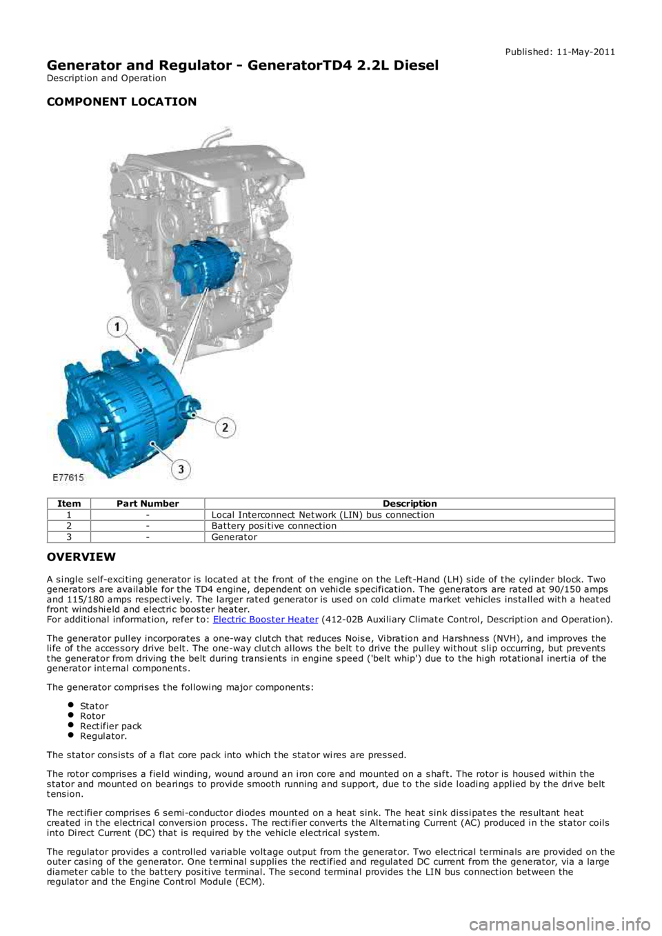
COMPONENT LOCATION
ItemPart NumberDescription
1-Local Interconnect Net work (LIN) bus connect ion2-Bat tery pos i ti ve connect ion
3-Generat or
OVERVIEW
A s i ngl e s elf-exci ti ng generator is locat ed at t he front of t he engine on t he Left -Hand (LH) s ide of t he cyl inder bl ock. Twogenerators are avail abl e for t he TD4 engine, dependent on vehi cl e s peci fi cat ion. The generat ors are rated at 90/150 ampsand 115/180 amps respecti vel y. The l arger rat ed generator is us ed on cold cl imat e market vehicles ins tall ed wit h a heat edfront winds hi eld and el ect ri c boos t er heat er.For addit ional informat ion, refer t o: Electric Boos ter Heater (412-02B Auxi li ary Cl imat e Control , Descripti on and Operat ion).
The generator pull ey incorporates a one-way clut ch that reduces Nois e, Vi brat ion and Harshnes s (NVH), and improves theli fe of t he acces s ory drive belt . The one-way clut ch al lows t he belt t o drive t he pul ley wi thout s li p occurring, but prevent st he generat or from driving t he belt during t rans ients in engine s peed ('belt whip') due to the hi gh rot at ional inert ia of thegenerator int ernal components .
The generator compri ses t he fol lowi ng major component s:
Stat orRotorRect ifier packRegul ator.
The s tat or cons is ts of a fl at core pack into which t he s tat or wi res are pres s ed.
The rot or compris es a fiel d winding, wound around an i ron core and mounted on a s haft. The rotor is hous ed wi thin thes tat or and mount ed on beari ngs to provi de s mooth running and s upport, due t o t he s ide l oadi ng appl ied by t he dri ve beltt ens ion.
The rect ifi er compris es 6 s emi -conductor di odes mount ed on a heat s ink. The heat s ink di ss i pat es t he res ult ant heatcreated in t he electrical convers ion proces s . The recti fi er converts the Al ternat ing Current (AC) produced i n the st ator coil sint o Di rect Current (DC) that is required by the vehicl e electrical sys tem.
The regulat or provides a control led variable volt age output from the generat or. Two electrical terminals are provi ded on theouter casi ng of the generat or. One t ermi nal s uppli es the rect ified and regul ated DC current from the generat or, via a largediamet er cable to the bat tery pos i ti ve terminal. The s econd terminal provides t he LIN bus connect ion bet ween theregulat or and the Engine Cont rol Modul e (ECM).
Page 1849 of 3229
Publi s hed: 11-May-2011
Generator and Regulator - GeneratorTD4 2.2L Diesel
Removal and Inst all ati on
Removal
Remove t he cover and dis connect the bat tery ground cabl e.
Refer t o: Specificati ons (414-00 Bat tery and Charging Sys tem -
General Informat ion, Specificati ons).
1.
Remove t he fuel fi lt er.
Refer t o: Fuel Fil ter (310-01B Fuel Tank and Lines - TD4 2.2L Dies el ,
Removal and Ins tall ati on).
2.
3. W ARNING: Make sure t o s upport the vehicle wit h axle
s tands .
Rais e and s upport t he vehi cl e.
3.
Remove t he engi ne undershi eld.
Refer t o: Engi ne Unders hi eld (501-02 Front End Body Panel s ,
Removal and Ins tall ati on).
4.
Remove t he acces sory dri ve bel t.
Refer t o: Acces sory Dri ve Belt (303-05B Acces sory Drive - TD4 2.2L
Di es el, Removal and Ins tal lat ion).
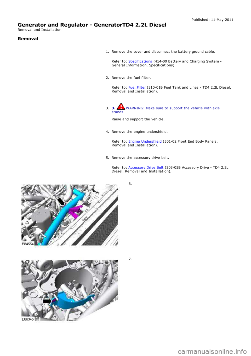
5. 6.
7.
Page 1853 of 3229
1. CAUTION: Make s ure that the mati ng faces are cl ean and
free of foreign mat eri al.
Inst all t he generat or.
1.
Inst all t he 2 generator bolt s .
T orque: 48 Nm 2.
Inst all t he acces sory dri ve bel t idl er pull ey.
T orque: 48 Nm 3.
Inst all t he acces sory dri ve bel t idl er pull ey dust cap.
4.
Connect t he generator electrical connect or.
5.
Connect t he batt ery cable t o t he generator.
T orque: 24 Nm 6.
At tach t he power s t eering flui d res ervoir.
7.
8. CAUTION: Make s ure that the mati ng faces are cl ean and
free of foreign mat eri al.
Inst all t he power s t eering pump.
T orque: 24 Nm 8.
Inst all t he fuel fi lt er support bracket.
T orque: 20 Nm 9.
At tach t he oil level indicator t ube to the fuel fil ter s upport bracket .
T orque: 10 Nm 10.
Inst all t he inner fuel fi lt er shi el d.
11.
Secure t he cool ant t op hos e.
12.
Inst all t he acces sory dri ve bel t.
Refer t o: Acces sory Dri ve Belt (303-05B Acces sory Drive - TD4 2.2L
Di es el, Removal and Ins tal lat ion).
13.
Inst all t he engi ne undershi eld.
Refer t o: Engi ne Unders hi eld (501-02 Front End Body Panel s ,
Removal and Ins tall ati on).
14.
Inst all t he fuel fi lt er.
Refer t o: Fuel Fil ter (310-01B Fuel Tank and Lines - TD4 2.2L Dies el ,
Removal and Ins tall ati on).
15.
Page 1920 of 3229
10-RH s i de turn s ignal lamp
11-Licens e pl ate lamps
12-LH rear l amp as s embl y13-RH rear lamp as s embly
14-LH headlamp as s embly
15-AFS cont rol module16-Headl amp l evel ing mot or
17-RH headlamp as s embly
18-Steering wheel modul e19-LH s t eering column mult ifunct ion s wit ch
20-High mount ed s top lamp
21-Central Junct ion Box (CJB)22-Revers e s wit ch (manual transmis si on only)
23-Stoplamp s wit ch
24-Rain/light s ensor25-Hazard flas her s wi tch
26-Light s wit ch modul e
27-Fuse 15A (F33)
CENTRAL JUNCTION BOX (CJB)
The CJB receives exteri or li ght ing relat ed inputs from t he fol lowing s wi tches:
Light s wit ch modul e- Side l amp pos it ion- Headlamp pos it ion- Automat ic (AUTO) posi ti on (if fi tt ed)- Front fog lamp swi tch (if fit ted)- Rear fog l amp s wit ch- Dimmer cont rol- Headlamp l evel ing control (if fit ted).Brake s wi tchLH s t eering column mult ifunct ion s wit ch for t urn si gnal i ndi cat ors and hi gh beam/headl amp flas hHazard flas her s wi tchRain/light s ensor (LIN si gnal ).
Circuit Protection
Two 60 Amp fus ibl e li nks in t he batt ery junct ion box protect the power feed to the CJB LH and RH li ght ing ci rcuit sres pect ively. All ext erior l ighti ng ci rcuit s are prot ect ed by Field Effect Trans is t ors (FETs ), l ocat ed in the CJB, which candetect overloads and s hort circuit s .
The FETs res pond to heat generated by increased current fl ow caus ed by a s hort ci rcuit . On a normal ci rcuit t his woul dcaus e t he fus e to bl ow. The FETs respond t o t he heat i ncrease and di s connect t he s uppl y t o t he affect ed ci rcuit . W hen t hefaul t is rect ified or t he FET has cool ed, t he FET wil l res et and operate t he circui t normall y. If t he faul t pers is ts the FET wi llcycle, di sconnect ing and reconnect ing t he power supply. The CJB s tores fault codes which can be ret rieved usi ng a LandRover approved diagnost ic sys tem. The fault code wil l identi fy t hat there is a fault on a part icular out put which as si s t infaul t det ect ion.
Alarm Indications
The exteri or li ght ing s ys tem is us ed for al arm arm and dis arm reques ts . W hen t he driver l ocks or unlocks the vehicle, avis ual i ndicat ion of a s uccess ful l ock or unlock reques t is di spl ayed t o t he dri ver by the hazard flas hers operat ing a numberof ti mes .For addit ional informat ion, refer t o: Anti -Theft - Act ive (419-01A Anti -Theft - Acti ve, Des cri pt ion and Operati on).
Lights On Warning chime
W hen t he i gni ti on in the off (power mode 0) or auxi liary (power mode 4) mode and the l ighti ng cont rol rotary swit ch is i nt he si de lamp or headlamp posi ti on, a warning chime wi ll s ound i f the driver's door is opened. This indicates t o t he dri vert hat t he exterior li ght s have been left on. The chime is generat ed from t he i ns t rument clus ter s ounder on receipt of ali ght s on s i gnal , a door open s ignal and an ignit ion swi tch off s ignal from t he CJB on the hi gh s peed CAN bus.
Crash Signal Activation
W hen a crash s ignal i s t rans mit ted from t he Rest rai nts Cont rol Modul e (RCM), t he CJB act ivat es the hazard flas hers andt he turn s ignal indicators in t he i ns t rument clus ter. The hazard fl ashers wil l continue to operate unt il t he ignit ion mode ischanged t o t he auxi liary power mode 4or the off power mode 0 or the RCM no longer trans mi ts the cras h si gnal .For addit ional informat ion, refer t o: Air Bag and Safet y Belt Pretens ioner Supplement al Res traint Syst em (SRS) (501-20BSuppl ement al Rest rai nt Sys tem, Des cri pti on and Operati on).
Headlamp Timer
The CJB cont rol s a headl amp t imer funct ion whi ch allows the headlamps t o remain on for a peri od of ti me after leaving t hevehi cl e. Thi s is a dri ver conveni ence feat ure which il lumi nat es t he dri veway after leaving t he vehicle.
This feat ure can onl y be acti vat ed by pulli ng t he high beam ' flas h-t o-pas s' on t he LH s t eering column mult ifunct ion s wi tch.It can be deacti vat ed eit her by ti ming out or by pull ing t he mul ti funct ion swi tch again.
The default s ett ing can be changed by a Land Rover or authorized deal er . The default t imi ng is s et t o 30s but can bechanged t o 0s (OFF), 30s (defaul t), 60s , 90s , 120s , 150s and 180s .For addit ional informat ion, refer t o: Informat ion and Mes s age Cent er (413-08 Informat ion and Mes s age Cent er, Des cript ionand Operat ion).
Page 2031 of 3229
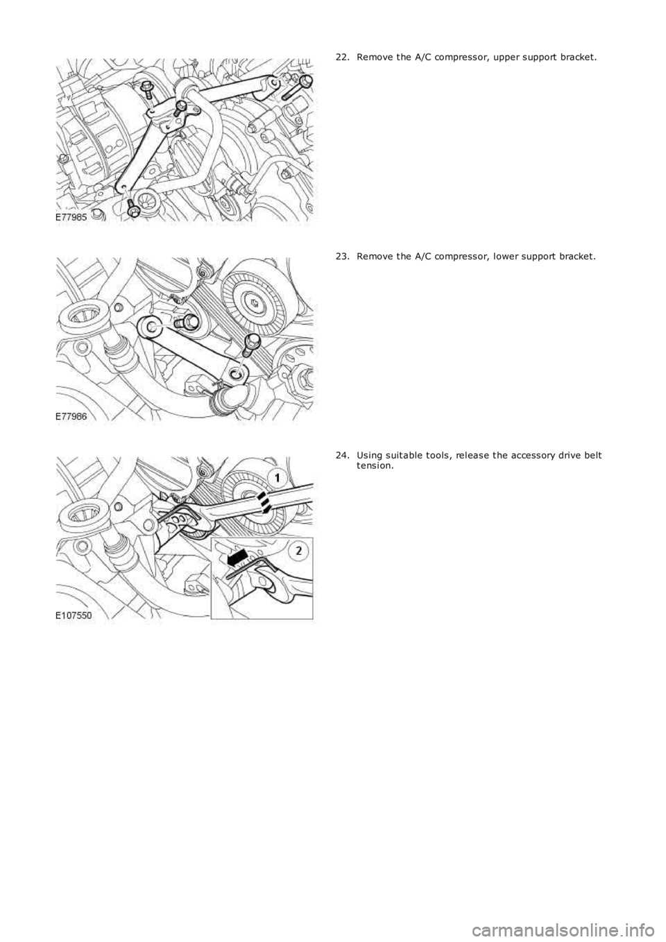
Remove t he A/C compress or, upper s upport bracket.22.
Remove t he A/C compress or, l ower support bracket.23.
Us ing s uit able t ools , rel eas e t he acces s ory drive beltt ens i on.24.
Page 2172 of 3229
Publi s hed: 11-May-2011
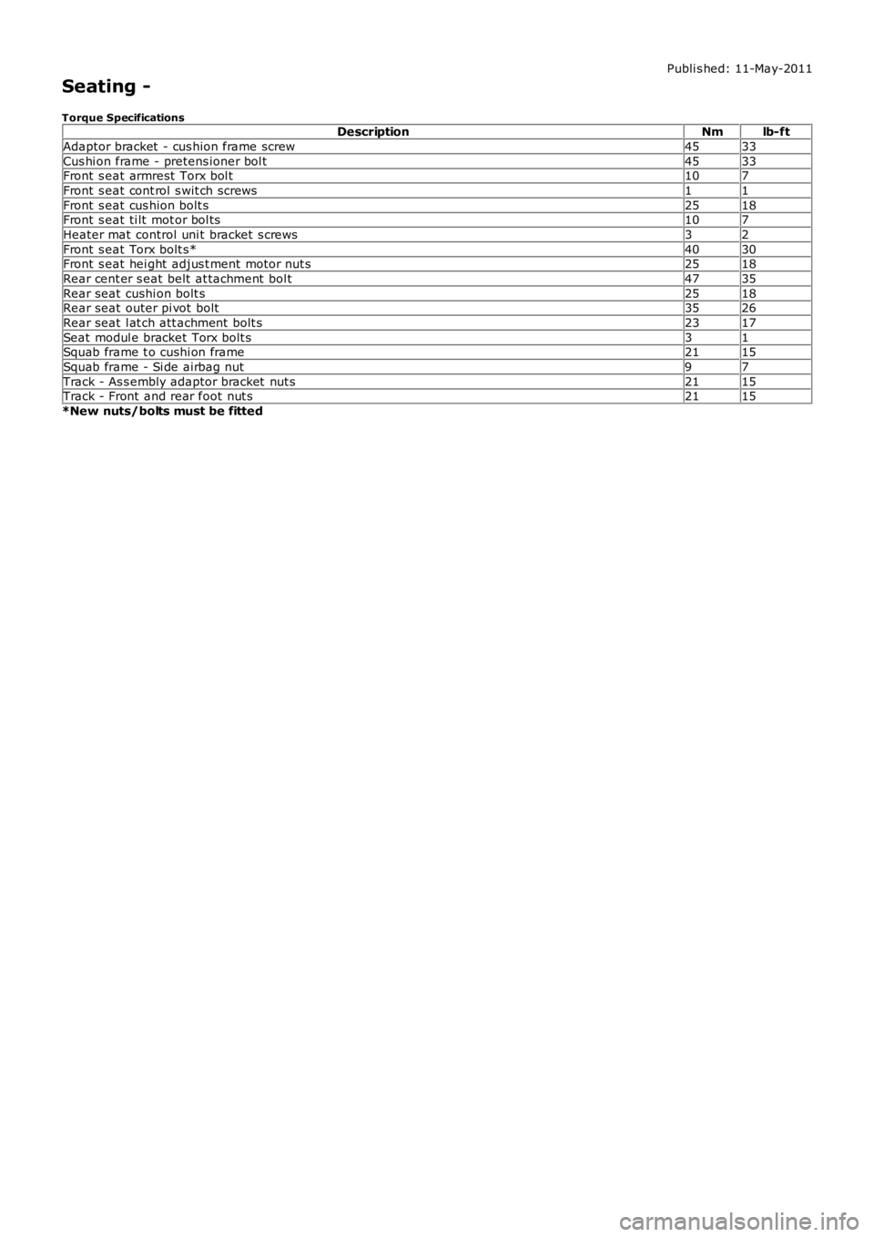
Seating -
Torque SpecificationsDescriptionNmlb-ft
Adaptor bracket - cus hion frame screw4533
Cus hi on frame - pretens ioner bol t4533Front s eat armrest Torx bol t107
Front s eat cont rol s wit ch screws11
Front s eat cus hion bolt s2518Front s eat ti lt mot or bol ts107
Heater mat control uni t bracket s crews32
Front s eat Torx bolt s*4030Front s eat hei ght adjus t ment motor nut s2518
Rear cent er s eat belt at tachment bol t4735
Rear seat cushi on bolt s2518Rear seat outer pi vot bolt3526
Rear seat l at ch att achment bolt s2317
Seat modul e bracket Torx bolt s31Squab frame t o cushi on frame2115
Squab frame - Si de airbag nut97
Track - As s embly adaptor bracket nut s2115Track - Front and rear foot nut s2115
*New nuts/bolts must be fitted
Page 2174 of 3229
3
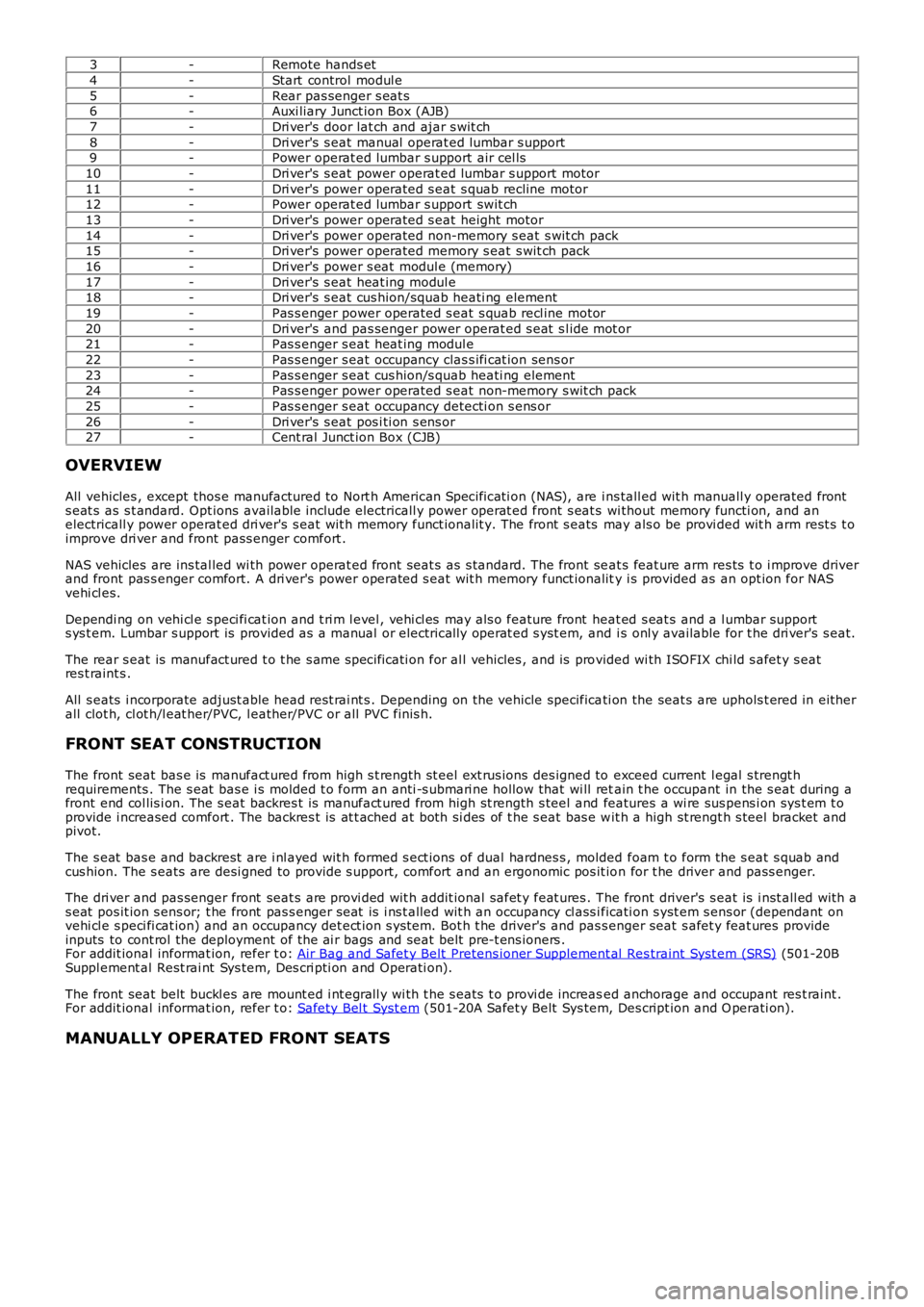
-Remote hands et
4 -Start control modul e
5 -Rear pas senger s eat s
6 -Auxi liary Junct ion Box (AJB)
7 -Dri ver's door lat ch and ajar s wit ch
8 -Dri ver's s eat manual operat ed lumbar s upport
9 -Power operat ed lumbar s upport air cel ls
10 -Dri ver's s eat power operat ed lumbar s upport motor
11 -Dri ver's power operated s eat s quab recline motor
12 -Power operat ed lumbar s upport swit ch
13 -Dri ver's power operated s eat height motor
14 -Dri ver's power operated non-memory s eat s wit ch pack
15 -Dri ver's power operated memory s eat s wit ch pack
16 -Dri ver's power s eat modul e (memory)
17 -Dri ver's s eat heat ing modul e
18 -Dri ver's s eat cus hion/squab heati ng element
19 -Pas s enger power operated s eat s quab recl ine motor
20 -Dri ver's and pas senger power operat ed s eat s l ide mot or
21 -Pas s enger s eat heat ing modul e
22 -Pas s enger s eat occupancy clas s ifi cat ion sens or
23 -Pas s enger s eat cus hion/s quab heati ng element
24 -Pas s enger power operated s eat non-memory s wit ch pack
25 -Pas s enger s eat occupancy detecti on s ens or
26 -Dri ver's s eat pos i ti on s ens or
27 -Cent ral Junct ion Box (CJB)
OVERVIEW
All vehicles , except thos e manufactured to Nort h American Specificati on (NAS), are i ns tall ed wit h manuall y operated front
s eat s as s t andard. Opt ions available include electricall y power operat ed front s eat s wi thout memory functi on, and an
electricall y power operat ed dri ver's s eat wit h memory funct ionalit y. The front s eats may als o be provi ded wit h arm rest s t o
improve dri ver and front pass enger comfort .
NAS vehicles are ins tal led wi th power operat ed front seat s as s tandard. The front se at s feat ure arm res ts t o i mprove driver
and front pas s enger comfort. A dri ver's power operated s eat wit h memory funct ionalit y i s provided as an opt ion for NAS
vehi cl es.
Dependi ng on vehi cl e s peci fi cat ion and t ri m l evel , vehi cl es may als o feature front h eat ed s eat s and a l umbar support
s ys t em. Lumbar s upport is provided as a manual or electrically operat ed s yst em, and i s onl y available for t he dri ver's s eat.
The rear s eat is manufact ured t o t he s ame s pecificati on for al l vehicles , and is pro vided wi th ISOFIX chi ld s afet y s eat
res t raint s .
All s eats i ncorporate adjust able head rest rai nt s . Depending on the vehicle specifica ti on the seat s are uphols t ered in eit her
all clot h, cl ot h/l eat her/PVC, l eather/PVC or all PVC finis h.
FRONT SEAT CONSTRUCTION
The front seat bas e is manufact ured from high s t rength st eel ext rus ions des igned to exceed current l egal s trengt h
requirements . The s eat bas e i s molded t o form an anti -s ubmari ne hollow that wi ll ret ain t he occupant in the s eat during a
front end col lis i on. The s eat backres t is manufact ured from high st rength s teel and features a wi re sus pens i on sys t em t o
provide i ncreased comfort . The backres t is at t ached at both si des of t he s eat bas e w it h a high st rengt h s teel bracket and
pivot.
The s eat bas e and backrest are i nl ayed wit h formed s ect ions of dual hardnes s , molded foam t o form the s eat s quab and
cus hion. The s eats are desi gned to provide s upport, comfort and an ergonomic pos it io n for t he driver and pass enger.
The dri ver and pas senger front seat s are provi ded wit h addit ional safet y feat ures . T he front driver's s eat is i nst all ed wit h a
s eat pos it ion s ens or; t he front pas s enger s eat is i ns t alled wit h an occupancy cl ass i ficati on s yst em s ens or (dependant on
vehi cl e s peci fi cat ion) and an occupancy det ect ion s ys tem. Bot h t he driver's and pas s enger seat s afet y feat ures provide
inputs to cont rol the deployment of the ai r bags and seat belt pre-t ens ioners .
For addit ional informat ion, refer t o: Air Bag and Safet y Belt Pretens ioner Supplement al Res traint Syst em (SRS) (501-20B
Suppl ement al Rest rai nt Sys tem, Des cri pti on and Operati on).
The front seat belt buckl es are mount ed i nt egrall y wi th t he s eats t o provi de increas ed anchorage and occupant res t raint .
For addit ional informat ion, refer t o: Safety Bel t Syst em (501-20A Safet y Belt Sys tem, Des cript ion and O perati on).
MANUALLY OPERATED FRONT SEATS
Page 2193 of 3229
Publi s hed: 11-May-2011
Seating - Front Seat Backrest Cover
Removal and Inst all ati on
Removal
• W ARNINGS:
To avoid accidental depl oyment , t he res traint s cont rol module backup power s upply mus t be deplet ed. W ait at leas tone mi nut e after dis connecti ng the bat tery ground cabl e(s ) before commenci ng any repair or adjus tment t o t hes uppl ement al res traint s yst em (SRS), or any component(s ) adjacent t o t he SRS s ens ors. Fail ure t o follow thes eins t ructi ons may res ult i n pers onal i njury.
Al ways wear s afet y glas s es when working on an air bag equipped vehi cl e and when handl ing an ai r bag module.Failure t o fol low this ins truct ion may res ult i n pers onal i njury.
To minimize t he pos s ibi lit y of premat ure depl oyment , do not us e radio key code s avers when working on thes uppl ement al res traint s yst em. Failure t o fol low this ins truct ion may res ult i n personal i njury.
To minimize t he pos s ibi lit y of i njury i n t he event of premat ure depl oyment , al ways carry a li ve air bag module wit ht he bag and trim cover point ed away from t he body. Fail ure t o follow thi s ins t ructi on may res ult i n pers onal injury.
To minimize t he pos s ibi lit y of premat ure depl oyment , live ai r bag modules mus t only be pl aced on work bencheswhich have been ground bonded and wit h t he trim cover facing up. Fail ure t o follow thes e i ns t ructi ons may res ult i npers onal i njury.
Never probe t he elect rical connect ors of air bag modules or any ot her s upplemental res t rai nt s ys tem component.Failure t o fol low this ins truct ion may res ult i n pers onal i njury.
Paint ing over the driver air bag module trim cover or ins trument panel coul d lead to det eriorat ion of t he t ri m coverand air bags. Do not for any reas on att empt to pai nt dis col ored or damaged air bag module trim covers or i nst rumentpanel . Ins tal l a new component . Fai lure to foll ow t his i nst ruct ion may res ul t in pers onal injury.
Make s ure that s ufficient ti me has el aps ed aft er dis connecti ng the bat tery ground cabl e(s ), before commencing workon t he s uppl ement al res traint s ys t em (SRS). Fail ure t o fol low thes e ins t ructi ons may res ult i n pers onal i njury.
• NOTE: Removal s t eps in t his procedure may cont ain i nst all ati on det ail s.
Di sconnect t he bat t ery ground cable.
Refer t o: Specificati ons (414-00 Bat tery and Charging Sys tem -General Informat ion, Specificati ons).
1.
Make t he SRS s ys t em s afe.
Refer t o: Standard W orks hop Pract ices (100-00 General Informat ion,Des cript ion and Operat ion).
2.
Remove t he front safet y belt buckle.
Refer t o: Front Safety Bel t Buckle (501-20A Safet y Belt Sys tem,Removal and Ins tall ati on).
3.