2006 LAND ROVER FRELANDER 2 belt
[x] Cancel search: beltPage 2481 of 3229
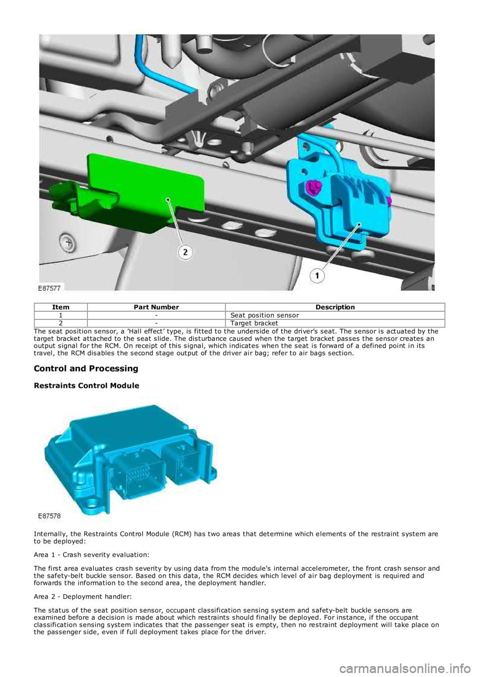
ItemPart NumberDescription
1-Seat pos it ion sens or2-Target bracket
The s eat pos it ion s ens or, a ’Hal l effect ’ type, is fit ted t o t he unders ide of t he dri ver’s s eat. The s ensor i s act uated by thet arget bracket at tached to the s eat s lide. The dis t urbance caus ed when the target bracket pas s es t he sens or creates anoutput s ignal for the RCM. On receipt of t hi s s ignal, which i ndicat es when t he s eat i s forward of a defined poi nt i n i tst ravel , the RCM dis ables t he s econd s t age out put of t he dri ver ai r bag; refer t o air bags s ect ion.
Control and Processing
Restraints Control Module
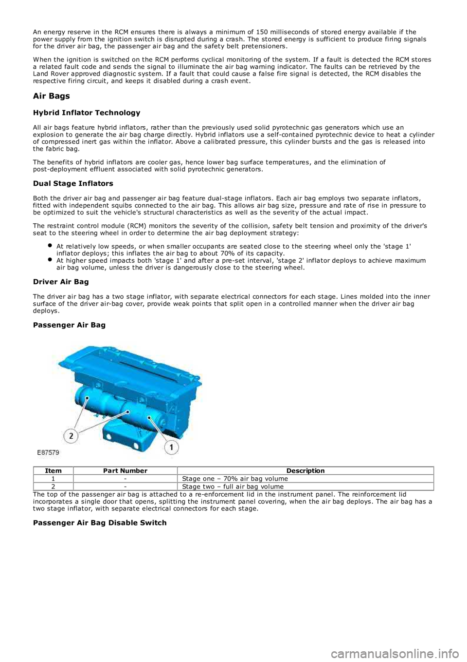
Int ernall y, the Res traint s Cont rol Module (RCM) has t wo areas t hat det ermi ne which el ement s of t he res traint s yst em aret o be deployed:
Area 1 - Cras h s everit y evaluati on:
The fi rs t area eval uat es cras h s everit y by us ing data from t he module's internal accel eromet er, t he front cras h sens or andt he safety-bel t buckle sens or. Bas ed on thi s data, t he RCM decides which l evel of air bag deployment is requi red andforwards t he informat ion t o t he s econd area, t he deployment handler.
Area 2 - Deployment handler:
The s tat us of the s eat posi ti on s ens or, occupant clas si fi cat ion s ens ing s yst em and safet y-belt buckle s ens ors areexamined before a decis ion i s made about which res t raint s s houl d finally be depl oyed. For ins tance, i f the occupantclas si fi cat ion s ens ing s yst em indicates t hat the pas senger s eat i s empty, t hen no res t raint deployment wil l take place ont he pas s enger s ide, even if full depl oyment t akes pl ace for t he dri ver.
Page 2482 of 3229
An energy reserve in the RCM ens ures there is al ways a mini mum of 150 mill is econds of s tored energy avai lable if t hepower supply from t he ignit ion s wi tch i s dis rupt ed during a cras h. The st ored energy i s s ufficient t o produce fi ri ng si gnal sfor t he dri ver ai r bag, t he pass enger ai r bag and the s afet y belt pret ensi oners .
W hen t he i gni ti on is s wi tched on t he RCM performs cycli cal monit ori ng of the sys tem. If a fault is det ect ed t he RCM s t oresa related fault code and s ends t he s ignal to il luminat e t he air bag warni ng indicator. The fault s can be retrieved by theLand Rover approved diagnos t ic s ys tem. If a faul t that coul d cause a fal se fi re si gnal i s det ected, the RCM dis ables t heres pect ive firing ci rcuit , and keeps it di s abl ed during a cras h event .
Air Bags
Hybrid Inflator Technology
All air bags feat ure hybrid i nflat ors , rat her than t he previous ly us ed s olid pyrotechni c gas generators which us e anexpl osi on t o generate t he air bag charge di rectl y. Hybrid i nflat ors us e a sel f-cont ained pyrotechnic device t o heat a cyl inderof compress ed i nert gas wit hin the i nfl at or. Above a cali brated press ure, t his cyli nder burs t s and t he gas is released intot he fabri c bag.
The benefit s of hybrid infl ators are cooler gas, hence lower bag s urface t emperat ures , and the el imi nat ion ofpost -deployment effluent ass ociat ed wit h s oli d pyrotechnic generators.
Dual Stage Inflators
Both the driver air bag and pass enger ai r bag feature dual-st age inflat ors . Each ai r bag empl oys two separat e i nflat ors ,fi tt ed wi th independent squibs connect ed t o the ai r bag. This allows ai r bag s ize, press ure and rat e of ri s e in pres sure t obe opti mized t o s uit t he vehicle's s t ructural characteris ti cs as well as t he s everity of the act ual i mpact .
The res t raint control modul e (RCM) moni tors t he s everi ty of the coll is ion, s afety bel t tens ion and proxi mit y of t he dri ver'ss eat t o t he s teering wheel in order t o det ermi ne the ai r bag depl oyment s t rat egy:
At rel ati vel y low speeds, or when s mal ler occupant s are s eat ed clos e t o t he st eeri ng wheel only the 'st age 1'inflat or deploys ; thi s inflates t he air bag t o about 70% of i ts capaci ty.At higher speed i mpact s both 's tage 1' and aft er a pre-s et interval , 's tage 2' inflat or deploys t o achi eve maximumair bag volume, unles s t he dri ver i s dangerous ly cl os e to t he s t eering wheel.
Driver Air Bag
The dri ver ai r bag has a two s tage i nflat or, wi th s eparat e electrical connect ors for each s t age. Lines mol ded int o t he inners urface of t he dri ver ai r-bag cover, provi de weak poi nts t hat s pl it open i n a control led manner when t he dri ver air bagdepl oys .
Passenger Air Bag
ItemPart NumberDescription
1-Stage one – 70% air bag volume
2-Stage t wo – full ai r bag vol umeThe t op of the pas senger air bag is att ached t o a re-enforcement l id in t he ins t rument panel . The reinforcement lidincorporat es a s ingle door t hat opens , spl it ti ng the ins trument panel coveri ng, when the ai r bag deploys . The air bag has at wo s tage i nflat or, wi th separat e electrical connect ors for each st age.
Passenger Air Bag Disable Switch
Page 2484 of 3229
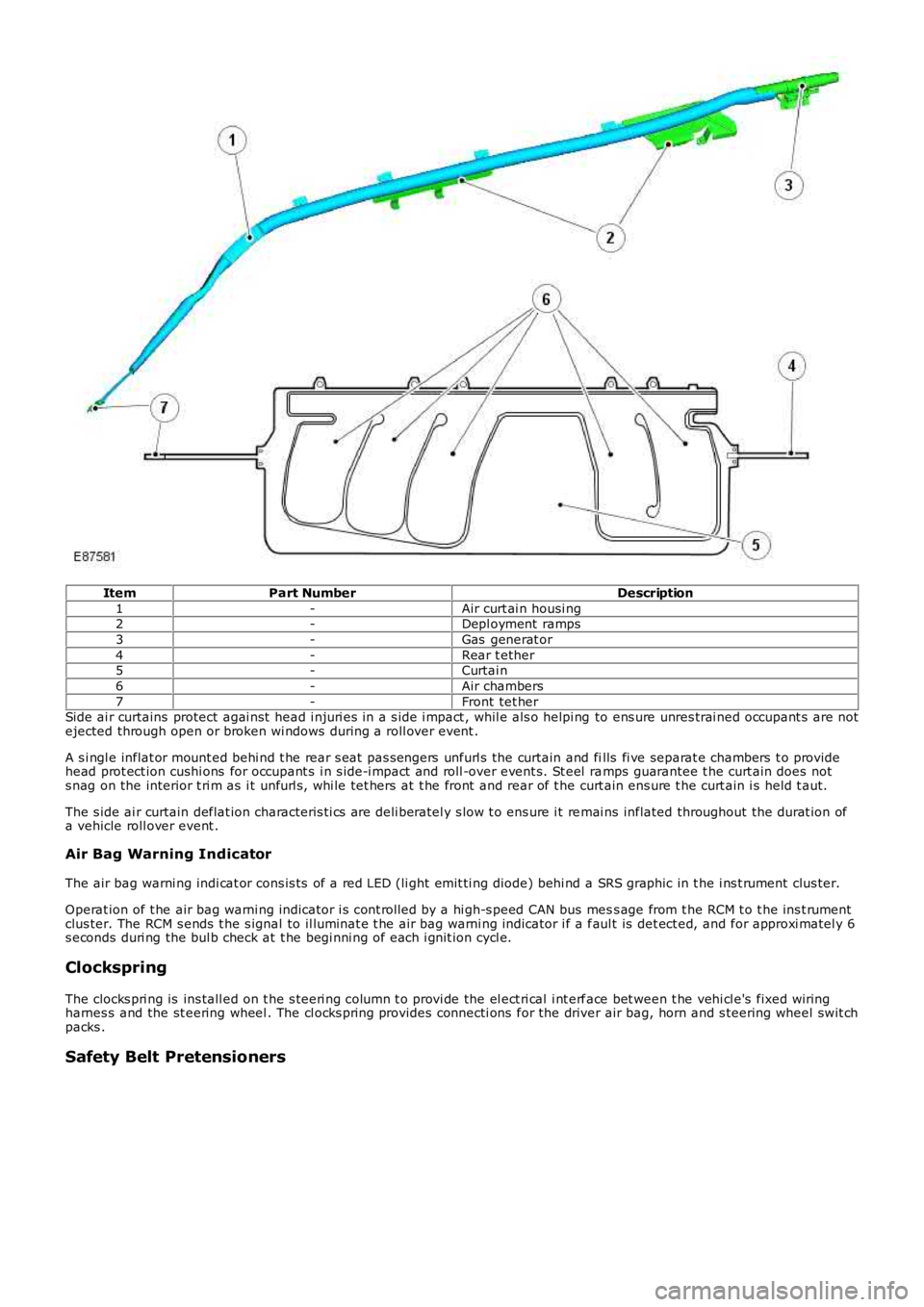
ItemPart NumberDescription
1-Air curt ai n housi ng2-Depl oyment ramps
3-Gas generat or
4-Rear t ether5-Curtai n
6-Air chambers
7-Front tet herSide ai r curtains protect agai nst head i njuri es in a s ide i mpact , whil e als o helpi ng to ens ure unres trai ned occupant s are notejected through open or broken wi ndows during a roll over event .
A s i ngl e inflat or mount ed behi nd t he rear s eat pas s engers unfurl s the curtain and fills fi ve separat e chambers t o providehead prot ect ion cushi ons for occupant s i n s ide-i mpact and roll -over event s. St eel ramps guarantee t he curt ain does nots nag on the interior t ri m as i t unfurl s , whi le tet hers at t he front and rear of t he curt ain ens ure t he curt ain i s held t aut.
The s ide ai r curtain deflat ion characteris ti cs are deli beratel y s low t o ens ure i t remai ns inflated throughout the durat ion ofa vehicle roll over event .
Air Bag Warning Indicator
The air bag warni ng indi cat or cons is ts of a red LED (li ght emit ti ng diode) behi nd a SRS graphic in t he i ns t rument clus ter.
Operat ion of t he air bag warni ng indicator i s cont rol led by a hi gh-s peed CAN bus mess age from t he RCM t o t he ins t rumentclus ter. The RCM s ends t he s ignal to il luminat e t he air bag warni ng indicator i f a faul t is det ect ed, and for approxi matel y 6s econds duri ng the bul b check at t he begi nni ng of each i gnit ion cycl e.
Clockspring
The clocks pri ng is ins tall ed on t he s teeri ng column t o provi de the el ect ri cal i nt erface bet ween t he vehi cl e's fixed wiringharnes s and the st eering wheel . The cl ocks pring provides connecti ons for the driver air bag, horn and s teering wheel swit chpacks .
Safety Belt Pretensioners
Page 2485 of 3229
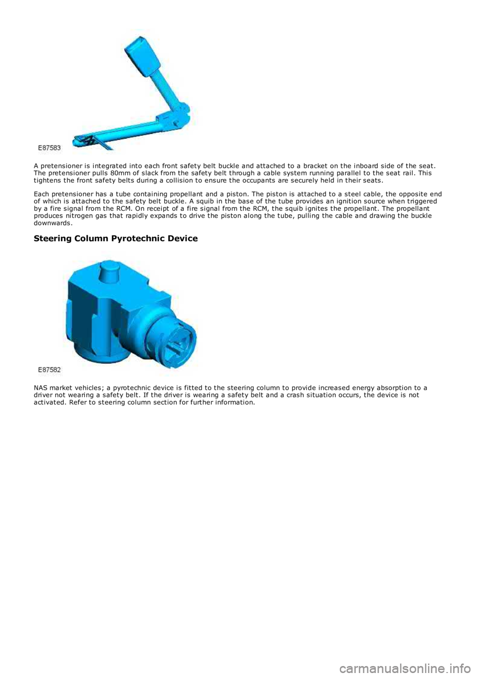
A pretens ioner i s i nt egrat ed int o each front s afet y belt buckl e and att ached to a bracket on t he i nboard s ide of t he seat .The pret ens i oner pull s 80mm of s lack from the safet y belt t hrough a cable sys tem running parallel t o t he s eat rail . Thi st ightens t he front safety belt s duri ng a coll is ion t o ens ure t he occupants are s ecurely held in t heir s eats .
Each pretens ioner has a t ube contai ning propell ant and a pis ton. The pis t on is at t ached t o a s t eel cable, the oppos it e endof which i s att ached t o t he s afety bel t buckle. A squib in the bas e of the tube provi des an ignit ion s ource when t ri ggeredby a fire s ignal from t he RCM. On recei pt of a fi re s i gnal from the RCM, t he s qui b igni tes t he propell ant . The propell antproduces ni trogen gas that rapi dl y expands t o dri ve t he pis ton al ong the t ube, pul ling the cable and drawing t he buckl edownwards .
Steering Column Pyrotechnic Device
NAS market vehicles ; a pyrot echnic device i s fit ted t o t he s teering column t o provi de increas ed energy absorpti on to adri ver not weari ng a s afet y belt . If t he dri ver i s weari ng a s afet y belt and a cras h s i tuati on occurs, t he devi ce is notact ivat ed. Refer t o s t eering column sect ion for furt her informati on.
Page 2510 of 3229
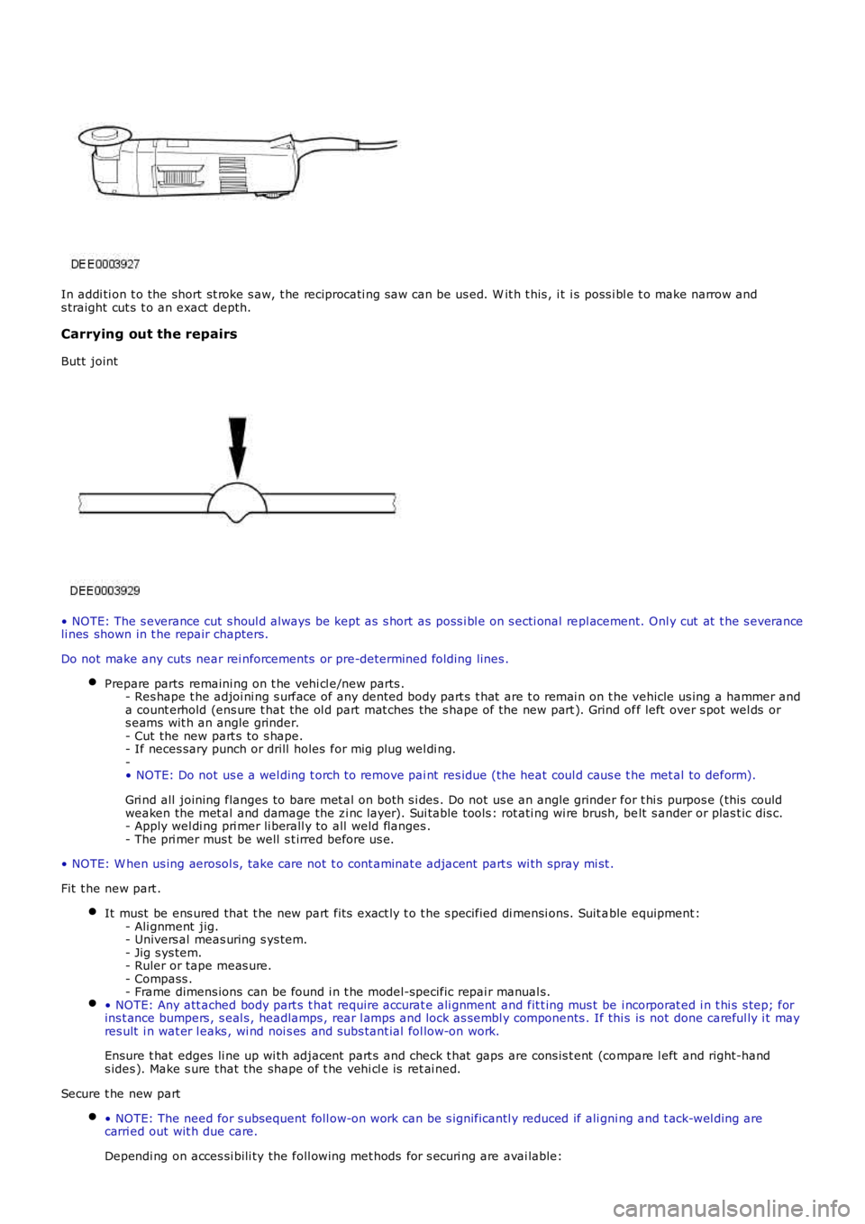
In addi ti on t o the short st roke s aw, t he reciprocati ng s aw can be us ed. W it h t his , it i s poss i bl e t o make narrow ands traight cut s t o an exact depth.
Carrying out the repairs
Butt joint
• NOTE: The s everance cut s houl d always be kept as s hort as poss i bl e on s ecti onal repl acement. Onl y cut at t he s everanceli nes shown in t he repair chapters.
Do not make any cuts near rei nforcements or pre-determined folding lines .
Prepare parts remaini ng on t he vehi cl e/new parts .- Res hape t he adjoi ni ng s urface of any dented body part s t hat are t o remai n on t he vehicle us ing a hammer anda count erhold (ens ure t hat the ol d part mat ches the s hape of the new part ). Grind off left over s pot wel ds ors eams wit h an angle grinder.- Cut the new part s to s hape.- If neces sary punch or drill holes for mig plug wel di ng.-• NOTE: Do not us e a wel ding t orch t o remove pai nt res idue (the heat coul d caus e t he met al to deform).
Gri nd all joining flanges to bare met al on both s i des . Do not us e an angle grinder for t hi s purpos e (this couldweaken the met al and damage the zi nc layer). Sui table tools : rot ati ng wi re brush, belt s ander or plas t ic dis c.- Apply wel di ng pri mer li berall y to all weld flanges .- The pri mer mus t be well s t irred before us e.
• NOTE: W hen us ing aerosol s, t ake care not t o cont aminat e adjacent part s wi th spray mi st .
Fit t he new part .
It must be ens ured that t he new part fit s exact ly t o t he s pecified di mensi ons. Suit able equipment :- Ali gnment jig.- Univers al meas uring s ys tem.- Jig s ys tem.- Ruler or tape meas ure.- Compass .- Frame dimens ions can be found i n t he model-specific repai r manual s.• NOTE: Any att ached body part s t hat require accurat e ali gnment and fit t ing mus t be i ncorporat ed i n t hi s s tep; forins t ance bumpers , s eal s , headlamps , rear l amps and lock as sembl y components . If thi s is not done careful ly i t mayres ult i n wat er l eaks , wi nd noi s es and subs tant ial fol low-on work.
Ensure t hat edges li ne up wi th adjacent part s and check t hat gaps are cons is t ent (compare l eft and right-hands ides ). Make s ure that the shape of t he vehi cl e is ret ai ned.
Secure t he new part
• NOTE: The need for s ubsequent foll ow-on work can be s ignificantl y reduced if ali gni ng and t ack-wel ding arecarri ed out wit h due care.
Dependi ng on acces si bili ty the foll owing met hods for s ecuri ng are avai lable:
Page 2512 of 3229
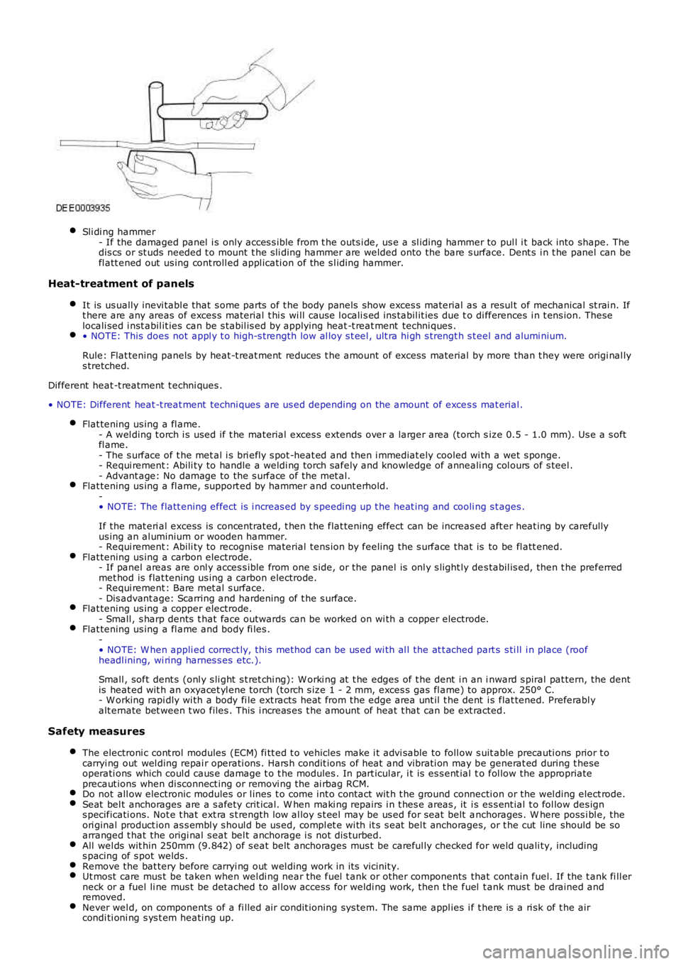
Sli di ng hammer- If the damaged panel i s only acces s ibl e from t he outs i de, us e a sl iding hammer to pul l i t back into shape. Thedis cs or st uds needed t o mount t he s li di ng hammer are welded onto the bare s urface. Dent s i n t he panel can befl att ened out us ing cont roll ed appl icati on of the s l iding hammer.
Heat-treatment of panels
It is us ually inevi tabl e that s ome parts of t he body panels show exces s material as a resul t of mechanical st rai n. Ift here are any areas of exces s material t hi s wi ll caus e l ocali s ed ins tabil it ies due to di fferences i n t ens ion. Theselocali sed i nst abil it ies can be s tabil is ed by applying heat -t reat ment techni ques .• NOTE: This does not appl y t o high-s t rength low al loy s t eel , ult ra hi gh s trengt h s teel and alumi nium.
Rule: Flat tening panels by heat -t reat ment reduces t he amount of excess material by more than t hey were origi nal lys tretched.
Different heat -t reatment t echni ques .
• NOTE: Different heat -t reat ment techni ques are us ed depending on the amount of exces s mat erial .
Flat tening us ing a fl ame.- A wel ding t orch i s used if t he material exces s extends over a larger area (t orch size 0.5 - 1.0 mm). Us e a s oftfl ame.- The s urface of t he met al i s bri efl y s pot -heat ed and then i mmediat ely cooled wi th a wet s ponge.- Requi rement : Abili ty to handle a weldi ng torch safely and knowledge of anneali ng col ours of s teel .- Advant age: No damage to the s urface of the met al.Flat tening us ing a fl ame, support ed by hammer and count erhold.-• NOTE: The flatt ening effect is i ncreas ed by s peedi ng up t he heat ing and cooli ng s tages .
If the mat eri al excess is concentrated, t hen the flat tening effect can be increas ed aft er heat ing by carefullyus ing an al uminium or wooden hammer.- Requi rement : Abili ty to recognis e material tens ion by feeling the s urface that is to be fl att ened.Flat tening us ing a carbon electrode.- If panel areas are onl y acces s ible from one s ide, or the panel is onl y s light ly des tabil is ed, then t he preferredmet hod is flat tening us ing a carbon electrode.- Requi rement : Bare met al s urface.- Dis advant age: Scarring and hardening of t he s urface.Flat tening us ing a copper electrode.- Small , s harp dents t hat face outwards can be worked on wi th a copper electrode.Flat tening us ing a fl ame and body fi les .-• NOTE: W hen appli ed correct ly, thi s method can be us ed wi th al l the at t ached part s s ti ll i n place (roofheadl ining, wi ring harnes s es etc.).
Small , soft dent s (onl y s li ght s t ret chi ng): W orki ng at t he edges of t he dent i n an inward s piral pat tern, the dentis heat ed wit h an oxyacet yl ene torch (t orch s ize 1 - 2 mm, exces s gas fl ame) to approx. 250° C.- W orking rapi dly wi th a body fi le ext racts heat from the edge area unt il t he dent is flat tened. Preferabl yalt ernate bet ween t wo files . This i ncreas es t he amount of heat t hat can be ext racted.
Safety measures
The electroni c cont rol modules (ECM) fi tt ed t o vehicles make i t advi sable to foll ow s uit able precauti ons prior t ocarryi ng out wel ding repai r operati ons . Hars h condit ions of heat and vibrati on may be generat ed during t heseoperati ons which coul d caus e damage t o t he modules . In part icul ar, i t is es s ent ial to fol low the appropriateprecaut ions when di sconnect ing or removi ng the ai rbag RCM.Do not all ow electronic modules or l ines t o come int o contact wit h t he ground connecti on or the wel ding elect rode.Seat bel t anchorages are a s afety crit ical. W hen maki ng repairs i n t hes e areas , it is es s ent ial t o fol low des igns pecificati ons. Not e t hat ext ra s t rength low al loy s t eel may be us ed for seat belt anchorages . W here poss i bl e, theori ginal product ion as s embl y s houl d be us ed, compl et e wi th it s s eat bel t anchorages, or t he cut line should be soarranged t hat the origi nal s eat bel t anchorage i s not dis turbed.All wel ds wit hin 250mm (9.842) of s eat bel t anchorages mus t be careful ly checked for weld quali ty, includings pacing of s pot welds .Remove the bat tery before carryi ng out wel ding work in it s vicinit y.Ut most care mus t be taken when wel di ng near the fuel t ank or other components that cont ain fuel. If the t ank fi ll erneck or a fuel li ne mus t be detached to al low access for weldi ng work, then t he fuel t ank mus t be drained andremoved.Never wel d, on components of a fi lled ai r condit ioning sys tem. The same appl ies i f there is a ri sk of t he aircondi ti oni ng s ys t em heati ng up.
Page 2527 of 3229
Clean t he affect ed s eam and re-t reat any expos ed met al areas wit h a sui table et ch phos phate primer.Treat affect ed area wit h an et ch-aci d pri mer.Apply appropri ate seam seal er as necess ary.appl y appropri ate colour coat (and under body s ealer as appl icable).
Provided acces s i s adequat e, apply seam seal er t o bot h s ides of a repai r joint . W here access is l imi ted to one s i de onl y,(e.g. box secti on), t reat t he affect ed box member wit h cavi ty wax.
Cavity Wax
Aft er repairs, al ways re-treat t hese areas wit h an approved cavit y wax. In addit ion, t reat all int eri or s urfaces whi ch havebeen dis turbed during repai rs whet her they have been treat ed i n product ion or not . Thi s includes all box members, cavit iesand door i nteriors .
Before wax inject ion, ensure t hat t he cavi ty to be treat ed i s free from any contaminati on or forei gn mat ter. W hereneces s ary, cl ear out any debri s.
Ensure t hat cavit y wax is appl ied after t he fi nal paint proces s and before refit ti ng any trim components .
Duri ng appl icati on ensure t hat t he wax covers all flanges and seam areas and t hat i t is adequately appl ied t o all repai redareas of both new and exi s ti ng panel s.
It should be not ed t hat new panel as sembl ies and complet e body shel ls are s uppl ied wi thout wax inject ion t reat ment.Ensure t hat s uch t reatment i s carri ed out aft er repairs .
Effect ive cavit y wax prot ect ion i s vit al. Always obs erve t he fol lowing poi nts :
Complet e all paint refini sh operati ons before wax appli cat ion.Check t he s pray pat tern of inject ion equipment.Mas k all areas not t o be waxed.Remove body fi xi ngs , s uch as s eat belt retract ors , if contami nati on is at al l l ikely.Move door gl ass es t o ful ly cl os ed pos it ion before t reati ng door interiors .Treat body areas normal ly covered by t ri m before refi tt ing i tems .Check t hat body and door drai n holes are cl ear after t he prot ect ive wax has dried.Keep all equipment cl ean, es peci ally wax inject ion nozzl es.
Page 2532 of 3229
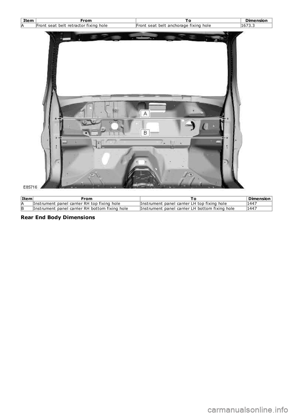
ItemFromT oDimension
AFront seat belt retract or fi xi ng holeFront s eat bel t anchorage fixi ng hol e1673.3
ItemFromT oDimensionAInst rument panel carrier RH top fixi ng hol eInst rument panel carrier LH top fixing hol e1447
BInst rument panel carrier RH bot t om fixing holeInst rument panel carrier LH bot tom fi xing hole1447
Rear End Body Dimensions