2006 LAND ROVER FRELANDER 2 belt
[x] Cancel search: beltPage 2630 of 3229
Publ is hed: 11-May-2011
Side Panel Sheet Metal Repairs - Rocker Panel
Removal and Installation
Removal
CAUTION: The rocker panel must be MIG slot brazed to the rocker panel inner reinforcement, which is DP600, (Dual
Phase steel). MIG plug we lds / spot w elds must not be use d.
• N O T E: T he ro cke r p a ne l i s s e rvi ce d a s a s e p a ra t e w e l d -o n p a ne l .
1. The rocker pane l i s repl ace d i n conjunct i on wi t h:
Front bumper cover
Front fender
Front door
Rear door
2. Fo r a d d i t i o na l i nf o rma t i o n re l a t i ng t o t hi s re p a i r p ro ce d ure
please see the following:
Fo r a d d i t i o na l i nf o rma t i o n, re f e r t o : Body and Frame
(501-26
Body Repairs - Vehicle Specific Information and Tolerance
Checks, Description and Operation) /
St a nd a rd W o rks ho p P ra ct i ce s
(100-00 Ge ne ra l I nf o rma t i o n,
Description and Operation).
3. Remove the fender.
4. Remove the front door.
Fo r a d d i t i o na l i nf o rma t i o n, re f e r t o : Front Door
(501-03 Body
Closures, Removal and Installation).
5. Remove the rear door.
Fo r a d d i t i o na l i nf o rma t i o n, re f e r t o : Rear Door
(501-03 Body
Closures, Removal and Installation).
6. Remove the front road wheel.
Fo r a d d i t i o na l i nf o rma t i o n, re f e r t o : Wheel and Tire
(204-04
Wheels and Tires, Removal and Installation).
7. Re mo ve t he re a r ro a d w he e l .
Fo r a d d i t i o na l i nf o rma t i o n, re f e r t o : Wheel and Tire
(204-04
Wheels and Tires, Removal and Installation).
8. LH side: Remove the hood release handle.
9. Remove the front seat.
Fo r a d d i t i o na l i nf o rma t i o n, re f e r t o : Front Seat
(501-10
Seating, Removal and Installation).
10. Remove the floor console.
Fo r a d d i t i o na l i nf o rma t i o n, re f e r t o : Floor Console
(501-12
Instrument Panel and Console, Removal and Installation).
11. Remove the front door aperture weatherseal.
12. Remove the rear door aperture weatherseal.
13. Remove the cowl side trim panel.
Fo r a d d i t i o na l i nf o rma t i o n, re f e r t o : Cowl Side Trim Panel
(501-05 Int eri or Trim and Ornament at i on, Removal and
Installation).
14. Re mo ve t he B -P i l l a r up p e r t ri m.
Fo r a d d i t i o na l i nf o rma t i o n, re f e r t o : B-Pillar Upper Trim Panel
(501-05 Int eri or Trim and Ornament at i on, Removal and
Installation).
15. Remove the RH & LH B-Pillar lower trims.
Fo r a d d i t i o na l i nf o rma t i o n, re f e r t o : B-Pillar Lower Trim Panel
(501-05 Int eri or Trim and Ornament at i on, Removal and
Installation).
16. Remove the rear quarter trim panel.
Fo r a d d i t i o na l i nf o rma t i o n, re f e r t o : Rear Quarter Trim Panel
(501-05 Int eri or Trim and Ornament at i on, Removal and
Installation).
17. Remove the RH & LH rocker panel inner trims.
18. Remove the rocker panel outer moulding.
19. Remove the back panel inner trim.
20. Remove the rear seat cushion.
Fo r a d d i t i o na l i nf o rma t i o n, re f e r t o : Rear Seat Cushion
(501-10
Seating, Removal and Installation).
21. Remove the front safety belt retractor.
Page 2631 of 3229
Fo r a d d i t i o na l i nf o rma t i o n, re f e r t o : Front Safety Belt Retractor(501-20A Safe t y Bel t Sys t em, Removal and Ins t al l at i on).
22. Re mo ve t he re a r ca rp e t s e ct i o n.
23. Release and lay aside the front carpet section.
24. Remove the B-Pillar side impact sensor.
Fo r a d d i t i o na l i nf o rma t i o n, re f e r t o : B-Pillar Side Impact Sensor
(501-20B Suppl ement al Res t rai nt Sys t em, Removal and
Installation).
25. Remove the C-Pillar side impact sensor.
Fo r a d d i t i o na l i nf o rma t i o n, re f e r t o : C-Pillar Side Impact Sensor
(501-20B Suppl ement al Res t rai nt Sys t em, Removal and
Installation).
26. Release and lay aside the bulkhead inner insulation.
27. Release and lay aside the wiring harness along the inner
ro cke r p a ne l .
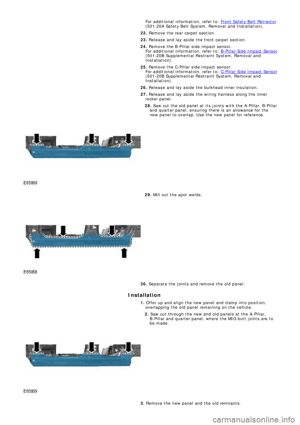
28. Saw cut the old panel at its joints with the A-Pillar, B-Pillar
and quart er panel, ens uring t here is an allowance for t he
new panel to overlap. Use the new panel for reference.
29. Mill out the spot welds.
30. Separate the joints and remove the old panel.
Installation
1. Offer up and align the new panel and clamp into position,
overlapping the old panel remaining on the vehicle.
2. Saw cut t hrough t he new and old panels at t he A-Pillar,
B-Pillar and quarter panel, where the MIG butt joints are to
be made.
3. Remove the new panel and the old remnants.
Page 2636 of 3229
Publ is hed: 11-May-2011
Rear End Sheet Metal Repairs - Quarter Panel
Removal and Installation
Removal
CAUTION: The quarter panel must be MIG slot brazed to the rocker panel inner reinforcement, which is DP600, (Dual
Phase steel). MIG plug we lds / spot w elds must not be use d in this are a.
• NOTE: The quarter panel is serviced as a separate weld-on panel.
• NOTE: There are NVH elements inside this panel, they are not serviced on the new panel. If damaged, a new element
will be required.
1. The quarter panel is replaced in conjunction with:
Rear bumper cover
Rear door
Quarter glass
Headliner
2. Fo r a d d i t i o na l i nf o rma t i o n re l a t i ng t o t hi s re p a i r p ro ce d ure
please see the following:
Fo r a d d i t i o na l i nf o rma t i o n, re f e r t o : Body and Frame
(501-26
Body Repairs - Vehicle Specific Information and Tolerance
Checks, Description and Operation) /
St a nd a rd W o rks ho p P ra ct i ce s
(100-00 Ge ne ra l I nf o rma t i o n,
Description and Operation).
3. Re move t he re a r bumpe r co ve r.
Fo r a d d i t i o na l i nf o rma t i o n, re f e r t o : Rear Bumper
(501-19
Bumpe rs , Re mo va l a nd Ins t a l l a t i on).
4. Remove the rear door.
Fo r a d d i t i o na l i nf o rma t i o n, re f e r t o : Rear Door
(501-03 Body
Closures, Removal and Installation).
5. Remove the headliner.
Fo r a d d i t i o na l i nf o rma t i o n, re f e r t o : Headliner - Vehicles
Without: Tilting Roof Opening Panel (501-05 Int eri or Tri m and
Ornamentation, Removal and Installation) /
Headliner - Vehicles With: Tilting Roof Opening Panel
(501-05
Int erior Trim and Ornamentat ion, Removal and Installat ion).
6. Re mo ve t he re a r d o o r s t ri ke r f ro m t he C-P i l l a r.
7. Remove the roof moulding, front and rear sections.
8. Re mo ve t he s i d e a i r curt a i n mo d ul e .
Fo r a d d i t i o na l i nf o rma t i o n, re f e r t o : Si d e A i r Curt a i n Mo d ul e
(501-20B Suppl ement al Res t rai nt Sys t em, Removal and
Installation).
9. Remove the rear quarter glass.
Fo r a d d i t i o na l i nf o rma t i o n, re f e r t o : Rear Quarter Window
Gl a s s (501-11 Glass, Frames and Mechanisms, Removal and
Installation).
10. Remove the front seat.
Fo r a d d i t i o na l i nf o rma t i o n, re f e r t o : Front Seat
(501-10
Seating, Removal and Installation).
11. Remove the floor console.
Fo r a d d i t i o na l i nf o rma t i o n, re f e r t o : Floor Console
(501-12
Instrument Panel and Console, Removal and Installation).
12. Remove the RH & LH rocker panel inner trims.
13. Remove the rear seat cushion.
Fo r a d d i t i o na l i nf o rma t i o n, re f e r t o : Rear Seat Cushion
(501-10
Seating, Removal and Installation).
14. Re mo ve t he re a r ca rp e t s e ct i o n.
15. Remove the rear safety belt retractor.
Fo r a d d i t i o na l i nf o rma t i o n, re f e r t o : Rear Safety Belt Retractor
(501-20A Safe t y Bel t Sys t em, Removal and Ins t al l at i on).
16. Remove the liftgate aperture weatherseal.
17. Remove the forced air extraction grille.
18. Remove the rear wheel and tire.
Fo r a d d i t i o na l i nf o rma t i o n, re f e r t o : Wheel and Tire
(204-04
Wheels and Tires, Removal and Installation).
19. Remove the rocker panel outer moulding.
20. Release and lay aside the wiring harness along the inner
Page 2664 of 3229
Publ is hed: 11-May-2011
Rear End Sheet Metal Repairs - Rear Lamp Mounting Panel
Removal and Installation
Removal
• NOTE: The rear lamp mounting panel is serviced as a separate weld-on panel.
• NOTE: There are NVH elements attached to the old panel, they are not serviced on the new panel. If damaged, new
elements will be required.
1. The rear lamp mounting panel is replaced in conjunction with:
Rear bumper cover
Re a r bumpe r a rma t ure
2. Fo r a d d i t i o na l i nf o rma t i o n re l a t i ng t o t hi s re p a i r p ro ce d ure
please see the following:
Fo r a d d i t i o na l i nf o rma t i o n, re f e r t o : Body and Frame
(501-26
Body Repairs - Vehicle Specific Information and Tolerance
Checks, Description and Operation) /
St a nd a rd W o rks ho p P ra ct i ce s
(100-00 Ge ne ra l I nf o rma t i o n,
Description and Operation).
3. Re move t he re a r bumpe r.
Fo r a d d i t i o na l i nf o rma t i o n, re f e r t o : Rear Bumper
(501-19
Bumpe rs , Re mo va l a nd Ins t a l l a t i on).
4. Disconnect both battery cables.
5. Remove the D-Pillar trim panel.
Fo r a d d i t i o na l i nf o rma t i o n, re f e r t o : D-Pillar Trim Panel
(501-05
Int erior Trim and Ornamentat ion, Removal and Installat ion).
6. Re mo ve t he re a r w he e l a nd t i re .
7. Remove t he rear quart er window moulding.
8. Remove the loadspace trim panel.
9. Remove the forced air extraction grille.
10. Release the insulating material and lay aside.
11. Release and lay aside the wiring harness.
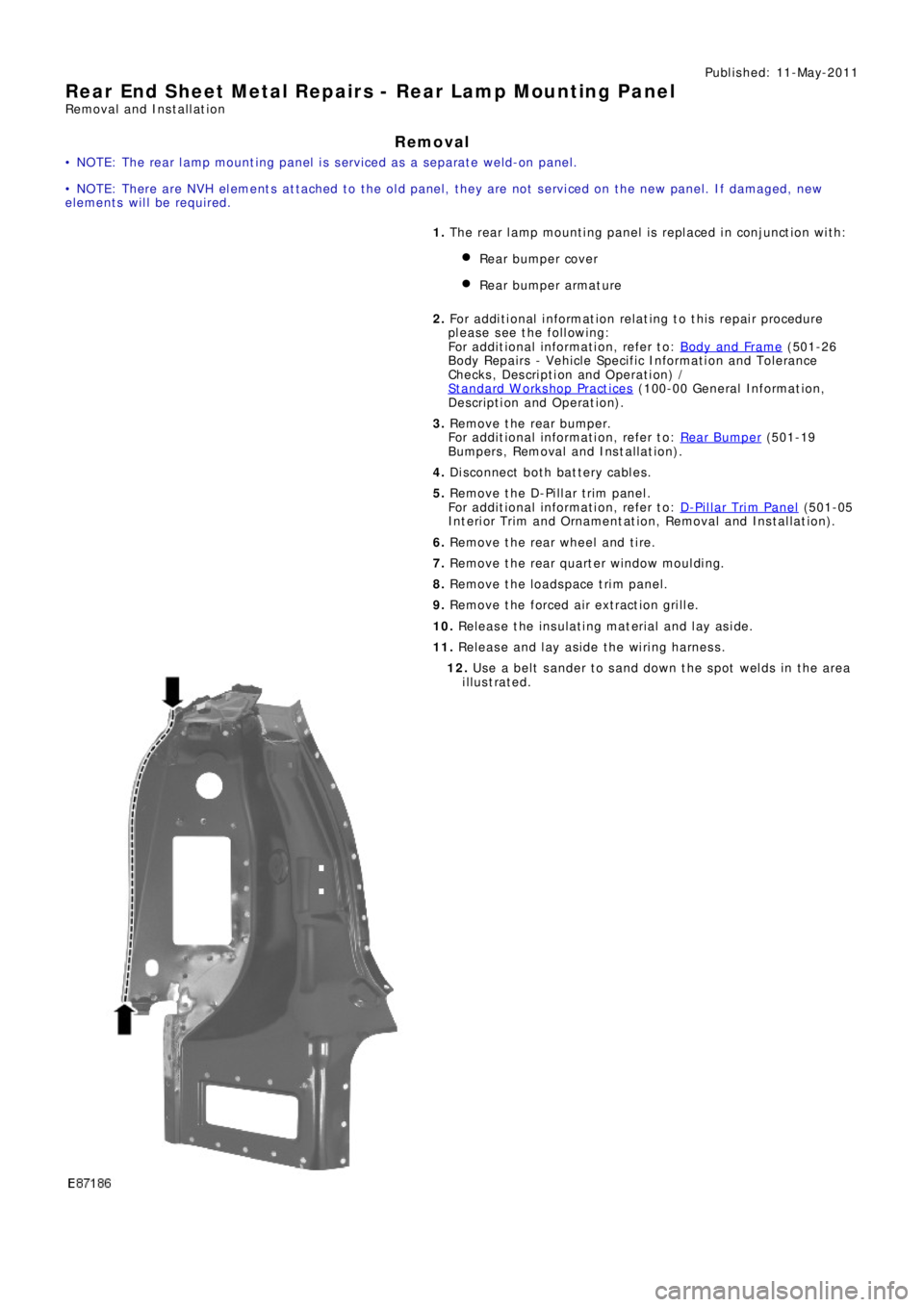
12. Use a belt sander to sand down the spot welds in the area
illustrated.
Page 2723 of 3229

Contents
3
R
Quick start
QUICK START ................................................... 7
Filling station information
FILLING STATION INFORMATION................... 33
Introduction
SYMBOLS GLOSSARY .................................... 35
LABEL LOCATIONS ......................................... 35
HEALTH AND SAFETY ..................................... 36
DATA RECORDING.......................................... 37
DISABILITY MODIFICATIONS ......................... 37
PARTS AND ACCESSORIES ............................ 37
Keys and remote controls
USING THE KEY .............................................. 40
GENERAL INFORMATION ON RADIO
FREQUENCIES ................................................ 40
USING THE REMOTE CONTROL ..................... 41
Locks
LOCKING AND UNLOCKING ............................ 44
Alarm
ARMING THE ALARM ..................................... 45
DISARMING THE ALARM ............................... 46
Seats
SITTING IN THE CORRECT POSITION ............ 47
MANUAL SEATS ............................................. 48
ELECTRIC SEATS ............................................ 49
HEAD RESTRAINTS ........................................ 51
REAR SEATS................................................... 51
HEATED SEATS............................................... 53
Seat belts
PRINCIPLE OF OPERATION ............................ 54
SEAT BELT REMINDER ................................... 55
FASTENING THE SEAT BELTS ........................ 56
SEAT BELT HEIGHT ADJUSTMENT................. 56
USING SEAT BELTS DURI NG PREGNANCY .... 57
Supplementary restraints system
PRINCIPLE OF OPERATION ............................ 58
AIRBAG WARNING LAMP ............................... 61
DISABLING THE PASSENGER AIRBAG ........... 62
AIRBAG SERVICE INFORMATION ................... 63
Child safety
CHILD SEATS ................................................. 64
BOOSTER CUSHIONS ..................................... 66
ISOFIX ANCHOR POINTS................................ 67
CHILD SAFETY LOCKS ................................... 69
Steering wheel
ADJUSTING THE STEERING WHEEL .............. 70
AUDIO CONTROL ........................................... 70
Lighting
LIGHTING CONTROL ...................................... 72
FRONT FOG LAMPS........................................ 72
REAR FOG LAMPS.......................................... 73
ADJUSTING THE HEADLAMPS....................... 73
HEADLAMP LEVELLING ................................. 73
HAZARD WARNING FLASHERS...................... 74
ADAPTIVE FRONT LIGHTING SYSTEM (AFS) . 74
DIRECTION INDICATORS ............................... 75
INTERIOR LAMPS .......................................... 76
APPROACH LAMPS ........................................ 76
CHANGING A BULB ........................................ 77
BULB SPECIFICATION CHART ........................ 86
Wipers and washers
WINDSCREEN WIPERS .................................. 87
RAIN SENSOR ................................................ 87
WINDSCREEN WASHERS............................... 88
HEADLAMP WASHERS................................... 88
REAR WINDOW WIPER AND WASHERS ........ 89
ADJUSTING THE WINDSCREEN WASHER JETS .
89
CHECKING THE WIPER BLADES .................... 90
CHANGING THE WIPER BLADES.................... 90
Windows and mirrors
ELECTRIC WINDOWS ..................................... 93
EXTERIOR MIRRORS ..................................... 94
ELECTRIC EXTERIOR MIRRORS .................... 95
INTERIOR MIRROR ........................................ 96
Instruments
INSTRUMENT PANEL OVERVIEW .................. 97
Information displays
TRIP COMPUTER ........................................... 99
INFORMATION MESSAGES ............................ 99
Page 2733 of 3229
13
Quick start
R
Seat belts and Child restraints
A warning indicator on the
instrument pack will illuminate to
alert you that the driver's or front
passenger's seat be lt is unbuckled.
Child seats
It is important to remember that the child's
weight, rather than age, determines the type of
seat that is required. See CHILD SEATS
(page 64).
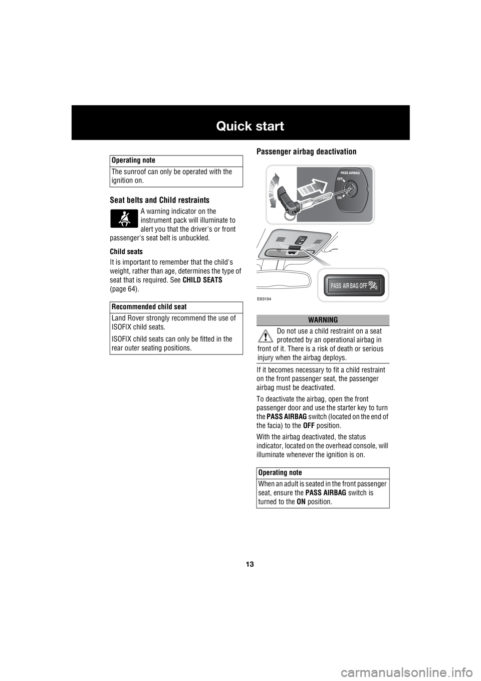
Passenger airbag deactivation
If it becomes necessary to fit a child restraint
on the front passenger seat, the passenger
airbag must be deactivated.
To deactivate the airbag, open the front
passenger door and use the starter key to turn
the PASS AIRBAG switch (located on the end of
the facia) to the OFF position.
With the airbag deactivated, the status
indicator, located on the overhead console, will
illuminate whenever the ignition is on.
Operating note
The sunroof can only be operated with the
ignition on.
Recommended child seat
Land Rover strongly recommend the use of
ISOFIX child seats.
ISOFIX child seats can only be fitted in the
rear outer seating positions.
WARNING
Do not use a child restraint on a seat
protected by an oper ational airbag in
front of it. There is a ri sk of death or serious
injury when the airbag deploys.
Operating note
When an adult is seated in the front passenger
seat, ensure the PASS AIRBAG switch is
turned to the ON position.
E83194
Page 2741 of 3229
21
Quick start
R
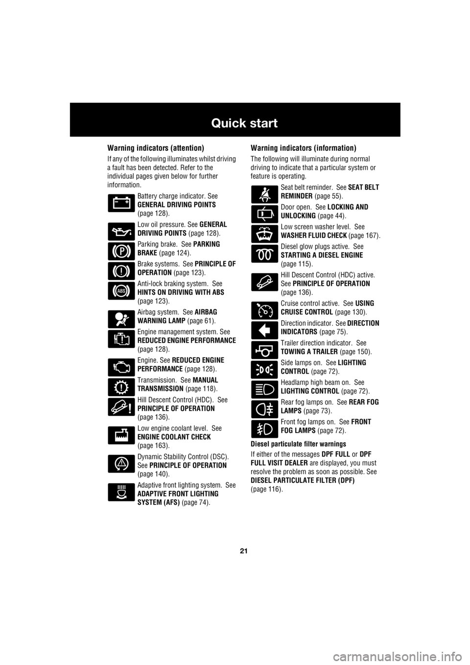
Warning indicators (attention)
If any of the following illuminates whilst driving
a fault has been detected. Refer to the
individual pages give n below for further
information.
Battery charge indicator. See
GENERAL DRIVING POINTS
(page 128).
Low oil pressure. See GENERAL
DRIVING POINTS (page 128).
Parking brake. See PARKING
BRAKE (page 124).
Brake systems. See PRINCIPLE OF
OPERATION (page 123).
Anti-lock braking system. See
HINTS ON DRIVING WITH ABS
(page 123).
Airbag system. See AIRBAG
WARNING LAMP (page 61).
Engine management system. See
REDUCED ENGINE PERFORMANCE
(page 128).
Engine. See REDUCED ENGINE
PERFORMANCE (page 128).
Transmission. See MANUAL
TRANSMISSION (page 118).
Hill Descent Control (HDC). See
PRINCIPLE OF OPERATION
(page 136).
Low engine coolant level. See
ENGINE COOLANT CHECK
(page 163).
Dynamic Stability Control (DSC).
See PRINCIPLE OF OPERATION
(page 140).
Adaptive front lighting system. See
ADAPTIVE FRONT LIGHTING
SYSTEM (AFS) (page 74).
Warning indicators (information)
The following will illuminate during normal
driving to indicate that a particular system or
feature is operating.
Seat belt reminder. See SEAT BELT
REMINDER (page 55).
Door open. See LOCKING AND
UNLOCKING (page 44).
Low screen washer level. See
WASHER FLUID CHECK (page 167).
Diesel glow plugs active. See
STARTING A DIESEL ENGINE
(page 115).
Hill Descent Control (HDC) active.
See PRINCIPLE OF OPERATION
(page 136).
Cruise control active. See USING
CRUISE CONTROL (page 130).
Direction indicator. See DIRECTION
INDICATORS (page 75).
Trailer direction indicator. See
TOWING A TRAILER (page 150).
Side lamps on. See LIGHTING
CONTROL (page 72).
Headlamp high beam on. See
LIGHTING CONTROL (page 72).
Rear fog lamps on. See REAR FOG
LAMPS (page 73).
Front fog lamps on. See FRONT
FOG LAMPS (page 72).
Diesel particulate filter warnings
If either of the messages DPF FULL or DPF
FULL VISIT DEALER are displayed, you must
resolve the problem as soon as possible. See
DIESEL PARTICULATE FILTER (DPF)
(page 116).
Page 2757 of 3229
37
Introduction
R
DATA RECORDING
Service data recording
Service data recorders in your vehicle are
capable of collecting and storing diagnostic
information about your vehicle. This potentially
includes information about the performance or
status of various syst ems and modules in the
vehicle such as engine, throttle, steering or
brakes.
In order to properly di agnose and service your
vehicle, Land Rover a nd service and repair
facilities may access vehicle diagnostic
information through a direct connection to
your vehicle.
Event data recording
Event data recorders are capable of collecting
and storing data during a crash or near-crash
event. The recorded information may assist in
the investigation of such an event. The
modules may record information about both
the vehicle and the oc cupants, potentially
including information such as:
• How various systems in your vehicle were
operating.
• Whether or not the driver and passenger
seat belts were buckled.
• How far, if at all, the driver was depressing
the accelerator and/or the brake pedal.
• How fast the vehicle was travelling.
• Where the driver was positioning the
steering wheel.
To access this information special equipment
must be connected directly to the recording
modules. Land Rover do not access event data
recorder information without obtaining
consent, unless pursuan t to court order or
where required by law enforcement, other
government authorities or third parties acting
with lawful authority. Other parties may seek to access the
information independe ntly of Land Rover.
DISABILITY MODIFICATIONS
Occupants with disabili ties which may require
modification of the vehi cle must contact a Land
Rover Dealer/Authorised Repairer before any
modifications are made.
PARTS AND ACCESSORIES
WARNINGS
The fitting of non-approved parts and
accessories, or the carrying out of
non-approved alterations or
conversions, may be dangerous and could
affect the safety of th e vehicle and occupants
and also invalidate the terms and conditions of
the vehicle warranty.
Land Rover will not accept any liability
for death, personal injury or damage to
property which may occur as a direct
result of fitment of non-approved accessories
or the carrying out of non-approved
conversions to La nd Rover vehicles.
Land Rover strongly advise against
making any modifications to the
suspension or steering system. This
could seriously affe ct the handling and
stability of the vehicle leading to loss of control
or roll-over.