2006 LAND ROVER FRELANDER 2 oil type
[x] Cancel search: oil typePage 22 of 3229
Do not t ouch t he glas s port ion of t he bulb.On no account s hould headlamps be s wi tched on wi th t he bulb removed from the headlamp.Bulb t es ti ng may only be carri ed out wit h the bul b ins t al led i n t he headl amp.Bulbs mus t be di spos ed of in accordance wit h the local aut horit y bye-laws .
Connectors and harnesses
The engi ne compart ment of a vehi cl e is a part icularl y host il e environment for el ect ri cal component s and connectors. Al waysobserve the foll owing:
Make s ure el ect ri cal ly related it ems are dry and oil free before di sconnect ing/connecti ng t es t equipment .Make s ure t hat dis connect ed mul ti pl ugs and s ens ors are prot ect ed from any pos s ibl e oil , coolant or other li qui dcont aminat ion. Any such contami nat ion could impair performance or l ead to component fail ure.Never force connectors apart or pull on t he wiring harnes s .Always make s ure locki ng t abs are dis engaged before di sconnect ing mul ti plugs etc. and make s ure that correctori ent ati on is achieved before connecti on.Make s ure t hat any protecti on covers, i nsul at ion et c. are replaced if dis t urbed.
Having confirmed t hat a component is fault y, carry out t he fol lowing:
Swit ch off t he ignit ion and di s connect t he batt ery.Remove the component and support t he dis connected harnes s .W hen replaci ng electrical components , keep oily hands away from electrical connect ions and make s ure that lockingt abs on connect ors are ful ly engaged.
Battery Disconnection/Connection
Always refer to the El ect ri cal Secti on of this manual - Bat tery Connecti on/Dis connecti on pri or t o at tempt ing t o connect ordis connect the bat tery.For addit ional informat ion, refer t o: Specificati ons (414-01 Bat t ery, Mount ing and Cables , Speci ficat ions).
Fuel Handling Precautions
The fol lowing informati on li s ts bas ic precauti ons which mus t be obs erved if fuel i s t o be handl ed s afely. It als o outl inesother areas of ris k which mus t not be i gnored. As t his informati on is is sued for basi c gui dance only, consul t your local Fi reDepart ment where any doubt as to personal and envi ronmental s afet y exi s ts - See al so Heal th and Safety Precaut ions .
General precaut ions
Always have t he correct type of fire ext inguis her cont aining Foam, CO2, Gas or powder acces s ible when handl ing ordrai ni ng fuel or dis mantl ing fuel s ys tems . Fire exti ngui shers mus t als o be l ocat ed in areas where fuel i s s tored.
Make s ure t hat sui table warning si gns are exhibit ed.
Keep all s ources of ignit ion wel l away from areas where fuel is bei ng handl ed.
Make s ure t hat any leadlamps are fl ameproof and kept clear of spi ll age.
• W ARNINGS:
Do not di sas s emble or reas s emble fuel sys tem components whils t vehicle is over a pit .
No one should be permi tt ed to repair component s as sociat ed wit h fuel wi thout fi rs t having s peci alis t t rai ni ng.
Always dis connect t he vehi cl e batt ery before carryi ng out dis ass embly, reas s embly or drai ning work on a fuel sys tem.
Fuel t ank and s ys t em drai ning
Drai ning mus t be carried out in accordance wit h t he procedures given in the relevant Fuel Syst em s ecti on of thi s manual .
• W ARNINGS:
Never drain fuel or work on a fuel sys t em whil e t he vehi cl e i s over a pi t. Ext raction or draining of fuel must becarri ed out in a well venti lated area.
Al ways at tach fuel vapor warning l abel s t o fuel t anks i mmediat ely after drai ni ng.
Contai ners us ed for s toring fuel must be cl early marked wit h t he cont ents and pl aced i n a safe s torage area whichmeets the requi rement s of the local authorit y.
CAUTION: Some fuel l ines are now i ns t alled wit h 'quick release' connectors. If a connect or i s damaged, no at t emptmus t be made t o repai r the connect or, a new fuel line and connect or(s ) as s embly must be ins tall ed.
Always release pipe cli ps full y before att empti ng t o dis connect fuel pipes.
Fuel tank repairs
CAUTION: No at tempt s hould be made to repair a pl ast ic fuel tank. If t he s truct ure of t he t ank is damaged, a new
Page 39 of 3229
Health Protection Precautions
Avoi d prol onged and repeat ed cont act wit h oil s, parti cularly us ed engine oi ls .W ear prot ect ive clot hing, including i mpervious gl oves where practi cable.Do not put oily rags i nt o pocket s .Avoi d contami nat ing cl ot hes, parti cularly underpants , wi th oi l.Heavi ly s oil ed clot hi ng and oil -i mpregnated foot wear s hould not be worn. Overall s mus t be cleaned regularly.First Ai d t reatment s hould be obt ained i mmediat el y for open cuts and wounds .Us e barrier creams , appl yi ng t hem before each work peri od, t o help the removal of oil from t he s ki n.W as h wi th soap and wat er to make s ure al l oi l is removed (s kin cl eans ers and nail brushes wi ll help). Preparati onscont aining lanol ine replace the nat ural s ki n oil s which have been removed.Do not us e gasol ine (pet rol ), keros ene (paraffin), di esel fuel (gas oi l), thi nners or s ol vent s for cleaning skin.If skin dis orders develop, obtain medical advice wi thout delay.W here practi cable, degreas e component s pri or t o handling.W here there is a ri s k of eye cont act , eye protecti on s houl d be worn, for exampl e chemical goggles or face s hiel ds ;in addi ti on an eye was h facil it y s houl d be provided.
Environmental Precautions
This s ecti on provides general informati on which can help t o reduce t he environment al i mpact s from the act ivit ies carriedout in workshops .
Emis s ions t o air
Many of the act ivit ies t hat are carried out i n works hops emit gas es and fumes whi ch can contribut e to global warmi ng,depl eti on of the ozone layer and/or the format ion of phot ochemical s mog at ground level. By cons ideri ng how t he works hopact ivi ti es are carried out , thes e gases and fumes can be mi nimi s ed, t hus reduci ng t he impact on t he envi ronment.
Exhaus t fumes
Runni ng car engines i s an es sent ial part of works hop act ivi ti es and exhaust fumes need t o be venti lated to at mos phere.However, the amount of t ime engi nes are runni ng and the pos it ion of t he vehi cle s hould be carefully cons idered at al lt imes , to reduce the releas e of poi s onous gas es and mini mis e t he i nconveni ence t o peopl e l iving nearby.
Solvent s
Some of t he cl eani ng agent s us ed are sol vent based and wil l evaporate rapidl y to atmos phere i f used carel ess l y, or i fcont ainers are l eft unseal ed. Al l contai ners mus t be firmly cl os ed when not requi red and s olvent should be used sparingly.W herever poss i bl e, sol vent s havi ng a l ow t oxi ci ty and flammabi li ty should be sel ect ed. Al ways foll ow t he ins t ructi onss uppl ied by t he s olvent manufact urer. Si mil arl y, many pai nt s are s olvent bas ed and the s pray s houl d be us ed in such away as t o reduce emi ss i ons t o a mini mum.
Refrigerant
It is i ll egal t o rel eas e any refrigerant int o t he atmos phere. Dis charge and repl acement of thes e mat eri al s from aircondi ti oni ng uni ts should onl y be carried out us ing t he appropri at e equipment .
Dis charges to water
Mos t works hops wi ll have t wo s ys t ems for di schargi ng wast e wat er - st orm drai ns and foul drains . Storm drains s houl d onlyreceive clean wat er i.e. rainwat er. Foul drai ns wil l accept many of the normal was t e wat er i .e. was hing wat er, detergent sand domest ic type was te BUT NOT oi l, petrol, s olvent , acids , hydraul ic fluid, anti freeze and si mil ar fl ui ds. If in doubt ,always cons ult the l ocal authori ty or wat er company.
Spill ages
Every precauti on mus t be taken t o prevent s pi ll age of oi l, fuel , sol vent s etc., reachi ng the drains . All handl ing of s uchmat erial s mus t take pl ace wel l away from drai ns and preferably i n an area wit h a s uit able contai ni ng wall t o preventdis charge int o drai ns or watercours es . If a spi llage occurs , it mus t be s oaked up immedi ately us i ng a s pil l ki t whereprovided.
Checkli s t
Spillage prevention:
Store li quids in a s ecure area.
Make s ure t hat taps on l iquid cont ai ners are s ecure and cannot be acci dent ally turned on.
Prot ect bulk st orage t anks from vandal is m by locki ng the val ves .
Trans fer li quids from one cont ai ner t o another i n an area away from open drai ns .
Ensure li ds are replaced s ecurel y on cont ainers .
Have s pi ll kit s availabl e near t o point s of s torage and liquid handl ing areas .
Spill Ki ts
Speci al mat eri als are avai lable to abs orb a number of di fferent subs tances. They can be in granular form, ready t o us e andare suppli ed in sui table cont ai ners . Dis posal of used spi ll absorbing mat eri al i s deal t wit h i n W as t e management .
Land contamination
Oil s , fuels and s olvents etc. can cont aminate any soi l wit h which t hey come int o cont act . Such materials MUST never bedis posed of by pouri ng on t o s oil and every precauti on mus t be t aken t o avoid s pil lage reaching s oil . W as te materials
Page 40 of 3229
s tored on open ground coul d eit her leak or have contami nati ng subs tances was hed off them that would cont aminate theland. Always s tore t hes e materi als i n s uit abl e s kips or s imi larly robus t cont ainers .
Legal compliance
Some s it es may have a di scharge cons ent for effl uent di scharge t o t he foul drai n for a car was h et c. It is ess enti al t o knowt he types of effluent which are al lowed t o be di scharged i nto t he drai n and t o check t he res ult s of any monit ori ng carri edout by the W ater Company.
W here paint s praying operat ions are carried out i t may be necess ary to apply to the Local Aut horit y for an ai r emis s ionsli cence t o operate the pl ant . If such a licence is necess ary, addit ional precaut ions wil l be neces s ary t o comply wi th therequirements and t he resul ts of any air quali ty moni toring mus t be checked regul arl y.
Checkli s t
Alw ays adhere to the following:
Know what legal cons ents and l icences apply t o t he operat ions.
Check t hat the emis s ions and dis charges compl y wit h l egal requi rements .
Waste Management
Pollut ion can be reduced by careful handli ng, s t orage and dis posal of all was te materials that occur on s it es. Legis lat ionmakes it i ll egal t o dis pose of was t e mat eri al s other t han to licens ed wast e carriers and dis pos al s it es.
This means t hat it i s neces sary t o not onl y know what the wast e mat eri al s are but als o to have the neces s arydocument at ion and licences .
Handl ing and s t orage of was te
Ensure t hat was t e mat erial s are not poured down the drai n or on t o s oil and are st ored in s uch a way t hat they do notes cape on t o l and or soi l.
All was te mus t be s egregat ed int o i ndi vi dual t ypes e.g. oils , met als , bat t eries , s crap component s etc. This wi ll prevent anyreacti on between di fferent materials and as s is t i n dis posal .
Dis pos al of was te
Dis pos e of wast e i n accordance wi th t he followi ng guidelines :
Fuel, hydraulic fluid, anti-freeze and oil: Keep s eparate and dis pos e of t o s peci alis t contract ors .
Refrigerant: Col lect in s peci ali st equipment and reus e.
Detergents: Safe to pour down t he foul drai n if di luted.
Paint, thinners: Keep separat e and dis pose of to speciali st contract or.
Components: Return t o s uppl ier for refurbi shment or dis as sembl e and reus e any s uit able part s . Dis pose ofremai nder i n ordi nary was te.
Small parts: Reuse any sui table parts , dis pos e of the remainder in ordinary was t e.
Metals: Can be s old i f separat e from general was t e.
T yres: Keep s eparate and di s pos e of t o s peci al is t cont ract or. DO NO T att empt to dis pos e of t yres by burni ng.
Components/materials containing asbestos: Keep separat e and dis pose of to speciali st contract or.
Oil and fuel wastes (e.g. rags, used spill kit material): Keep s eparate and dis pos e of t o s peci alis t contract ors .
Air filters: Keep s eparat e and dis pose of to s peciali st contract ors .
Rubber/plastics: Dis pos e of i n ordi nary was te.
Hoses: Di s pos e of i n ordinary was te.
Batteries: Keep separat e and dis pose of to speciali st contract ors .
Air bags - DANGER EXPLOSIVES: Keep s eparate and dis pos e of t o s peci alis t contract ors .
Electrical components: Return to suppli er for refurbis hment or dis ass emble and reus e any s uit abl e components .Dis pos e of remai nder in ordinary wast e.
Catalytic converters: May be s ol d i f kept s eparate from general wast e.
Packaging: Compact/recycl e as much as pos s ible and di s pos e of i n ordinary was te.
Office/paper waste: Recycl e paper and t oner and i nk cart ridges , dis pos e of remainder in ordinary was t e.
Noise
Car alarm t es t ing, panel beati ng, runni ng engi nes , us ing ai r tools et c. are operat ions which i nvariably produce a largeamount of noi se. The l ocati on of s uch act ivit ies and als o the t ime of day must be carefull y cons idered havi ng regard to theproximit y of hous es s chools et c.
Page 44 of 3229
Publi s hed: 11-May-2011
General Information - Road/Roller Testing
Des cript ion and Operat ion
Road or roll ing road t es t ing may be carri ed out for various reasons and a procedure det ail ing pre-t es t checks , throughengi ne s tarti ng and s topping, pre-driving checks , on-t es t checks to final checks on complet ion of t he tes t are given.
Unles s complete vehi cl e performance is bei ng checked, t he ful l road t est procedure need not be carried out . Ins tead, t hos eit ems part icularly relevant t o t he s yst em(s) bei ng checked can be ext racted.
Pre-Test Checks
W ARNING: If t he brake s yst em hydraul ic fluid level i s l ow, pedal travel i s exces si ve or a hydraulic leak is found, donot att empt to road t est t he vehicle unt il t he reas on for t he low fl ui d l evel, excess ive pedal travel or hydraulic leak isfound and rect ified.
It is s ugges t ed that pre-t es t and funct ional t es ts of t hose sys tems/circuit s whi ch affect t he safe and l egal operati ons oft he vehi cl e, s uch as brakes , light s and s teeri ng, should al ways be carri ed out before the road or roll ing road tes t .
Engi ne oil l evelEngi ne cool ant levelTires, for correct pres sure, compat ible types and tread patt erns , and wear wi thi n limi ts .There i s s ufficient fuel in the t ank to compl ete the t est .Check al l around the engine, t rans mis s ion and under the vehicle for oil , coolant , hydraul ic and fuel l eaks . Make anote of any apparent leaks and wipe off t he surrounding areas t o make it easi er to identi fy t he extent of the leakon complet ion of t he tes t.
Starting the Engine
• NOTE: On i nit ial dri ve away from cold and wit hi n t he fi rs t 1.5 km (1 mile), do not depress accelerat or pedal beyond halft ravel unt il t he vehi cl e has att ained a minimum s peed of 25 km/h (15 mil es /h). Never operat e at high engi ne speed or wi tht he accelerat or pedal at ful l travel whil st the engine i s cold.
With the ignition off, check:
The parking brake is appli ed.Automatic transmission: The s el ect or lever is i n 'P' - PARK.Manual transmission: The gear l ever i s in NEUTRAL.All i ns t rument gauges read zero.
With the ignition on, check:
Igni ti on cont roll ed warni ng li ght s come on.Engi ne t emperature gauge regis t ers a readi ng compat ibl e wi th t he engine t emperat ure.Fuel gauge regi st ers a reading appropriate to the fuel l evel i n t he tank.The operati on of the parki ng brake warning l ight and fl ui d l evel warni ng indicator light.
On Road Test Check:
CAUTION: At commencement of road tes ti ng, check the brake operati on while s ti ll travel li ng at low speed beforecont inuing wit h t he tes t. If t he brakes pul l to one si de, or appear to be ot herwi se fault y, do not cont inue wit h t he roadt es t unti l the fault has been found and rect ified.
The parking brake releas es completel y.Gear changing i s s mooth, and t here are no abnormal noi s es or vi brati ons from t he t rans mis s ion.The engi ne power out put is s ati s factory, accel erati on is smoot h and accel erator pedal operat ion is not s ti ff orheavy, and engi ne s peed ret urns t o idl e correctl y.There i s no exces s ive or abnormall y colored s moke from t he engi ne under normal driving, heavy l oad or overruncondi ti ons .Steering operat ion i s s moot h, accurat e, not exces s ively heavy or wit h exces s ive free pl ay or vibrat ion. Does not pul lt o one s ide and s elf centres smoot hly after corneri ng.All i ns t rument s regis t er the correct readi ngs and operate correctl y.Swit ches and controls operat e s moothl y and posi ti vel y, warning or i ndi cat or light s operate correctl y and thedirect ion i ndi cat or cont rol s elf cancels when the s t eering i s ret urned t o t he s traight ahead pos it ion.Heati ng and vent il at ion sys tems work correct ly and effect ively.Brakes operate efficientl y.
Brake Testing
Avoi d brake t es ti ng on busy roads where i t can caus e i nconveni ence or danger t o ot her road users.
CAUTION: Brake t es ti ng which i ncludes heavy brake appl icati ons should not be carri ed out wit h new brake pads /dis csunti l the component s have bedded-i n. New brake fri ct ion component s wi ll not reach ful l efficiency unt il t he beddi ng-inprocess is complet e. Not e t hat when new parking brake shoes or rear brake di scs have been ins t al led, it i s es sent ial thatt he 'beddi ng-in' procedure i s carri ed out.For addit ional informat ion, refer t o: Parking Brake Shoes Bedding-In (206-05 Parking Brake and Actuati on, GeneralProcedures).
Test t he brakes at s everal speeds wit hin the normal operat ing range usi ng both light and heavy pedal pres s ure. Note anyt endency to snat ch, pull or drag, and any undue del ay in appli cat ion or release.
Page 97 of 3229
Publi shed: 20-Jul-2011
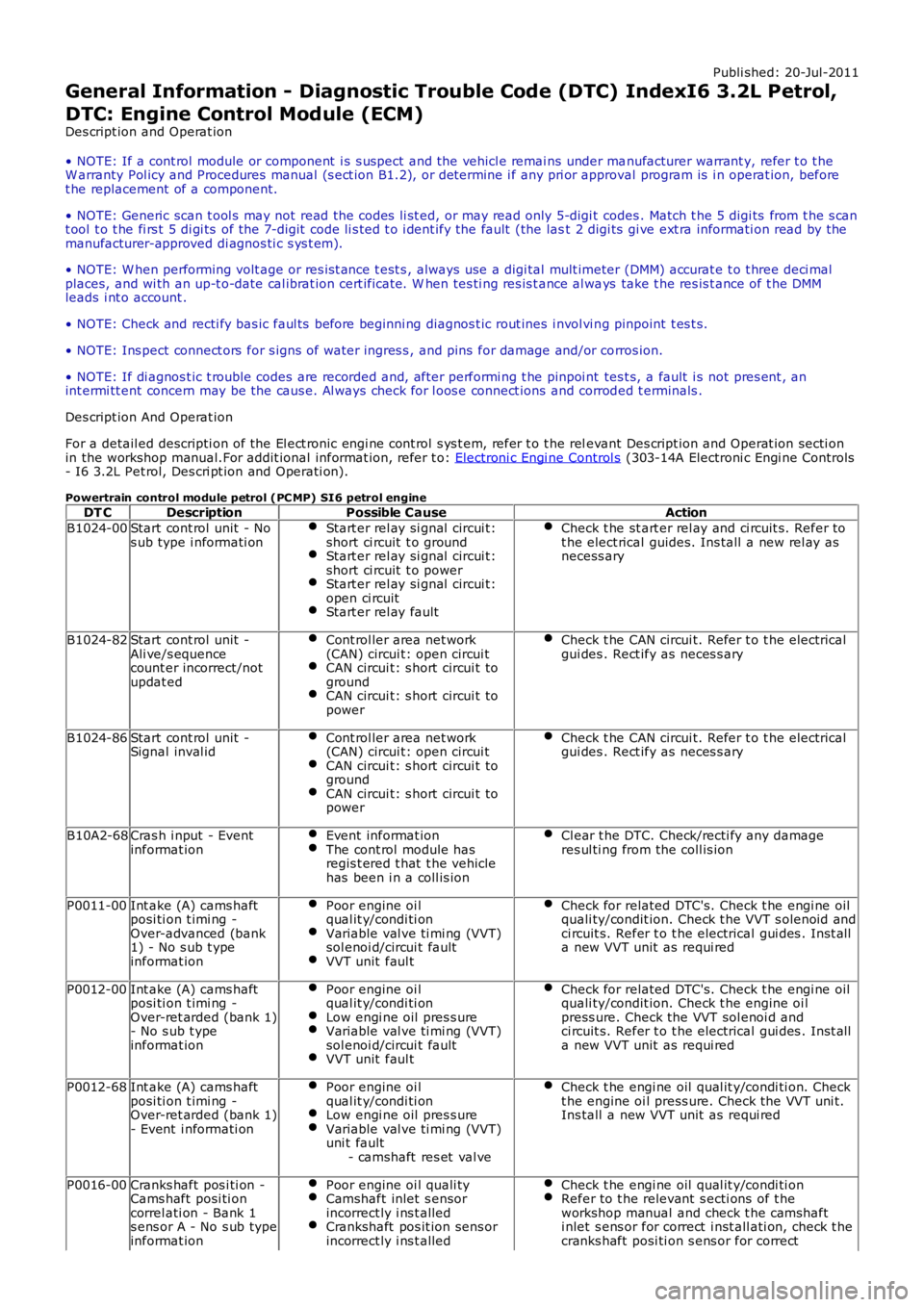
General Information - Diagnostic Trouble Code (DTC) IndexI6 3.2L Petrol,
DTC: Engine Control Module (ECM)
Des cript ion and Operat ion
• NOTE: If a cont rol module or component i s s uspect and the vehicl e remai ns under manufacturer warrant y, refer t o t heW arranty Pol icy and Procedures manual (s ect ion B1.2), or determine i f any pri or approval program is i n operat ion, beforet he replacement of a component.
• NOTE: Generic scan t ool s may not read the codes li st ed, or may read only 5-digi t codes . Match t he 5 digi ts from t he s cant ool t o t he fi rs t 5 di gi ts of the 7-digit code li s ted t o i dent ify the fault (the last 2 digi ts gi ve ext ra informati on read by themanufacturer-approved di agnos ti c s ys t em).
• NOTE: W hen performing volt age or res is t ance t est s , always use a digi tal mult imeter (DMM) accurat e t o t hree deci malplaces, and wi th an up-t o-date cal ibrat ion cert ificate. W hen tes ti ng res is t ance al ways take t he res is t ance of t he DMMleads i nt o account .
• NOTE: Check and recti fy bas ic faul ts before beginni ng diagnos t ic rout ines i nvol vi ng pinpoint t es t s.
• NOTE: Ins pect connect ors for s igns of water ingres s , and pins for damage and/or corros ion.
• NOTE: If di agnos t ic t rouble codes are recorded and, after performi ng t he pinpoi nt tes t s, a fault i s not pres ent , anint ermi tt ent concern may be the caus e. Al ways check for l oos e connect ions and corroded t erminals .
Des cript ion And Operat ion
For a detail ed descripti on of the El ect ronic engi ne cont rol s ys t em, refer t o t he relevant Des cript ion and Operat ion secti onin the workshop manual.For addit ional informat ion, refer t o: Electroni c Engi ne Control s (303-14A Electroni c Engi ne Controls- I6 3.2L Pet rol, Des cri pt ion and Operati on).
Powertrain control module petrol (PC MP) SI6 petrol engineDT CDescriptionPossible CauseAction
B1024-00Start cont rol unit - Nos ub type i nformati onStart er rel ay si gnal circui t:short ci rcuit t o groundStart er rel ay si gnal circui t:short ci rcuit t o powerStart er rel ay si gnal circui t:open ci rcuitStart er rel ay fault
Check t he st art er rel ay and ci rcuit s. Refer tot he elect rical guides. Ins tall a new rel ay asnecess ary
B1024-82Start cont rol unit -Ali ve/s equencecount er incorrect/notupdat ed
Cont rol ler area net work(CAN) circui t: open circui tCAN circui t: s hort circui t togroundCAN circui t: s hort circui t topower
Check t he CAN circui t. Refer t o t he electricalgui des . Rect ify as neces s ary
B1024-86Start cont rol unit -Signal inval idCont rol ler area net work(CAN) circui t: open circui tCAN circui t: s hort circui t togroundCAN circui t: s hort circui t topower
Check t he CAN circui t. Refer t o t he electricalgui des . Rect ify as neces s ary
B10A2-68Cras h i nput - Eventinformat ionEvent informat ionThe cont rol module hasregis t ered t hat t he vehiclehas been i n a coll is ion
Cl ear t he DTC. Check/recti fy any damageres ul ti ng from the coll is ion
P0011-00Int ake (A) cams haftposi ti on t imi ng -Over-advanced (bank1) - No s ub t ypeinformat ion
Poor engine oi lqual it y/condi ti onVariable val ve ti mi ng (VVT)sol enoi d/circui t faultVVT unit faul t
Check for related DTC's. Check t he engi ne oilquali ty/condit ion. Check t he VVT s olenoid andci rcuit s. Refer t o t he electrical gui des . Inst alla new VVT unit as requi red
P0012-00Int ake (A) cams haftposi ti on t imi ng -Over-ret arded (bank 1)- No s ub t ypeinformat ion
Poor engine oi lqual it y/condi ti onLow engi ne oil pres s ureVariable val ve ti mi ng (VVT)sol enoi d/circui t faultVVT unit faul t
Check for related DTC's. Check t he engi ne oilquali ty/condit ion. Check t he engine oi lpress ure. Check the VVT sol enoi d andci rcuit s. Refer t o t he electrical gui des . Inst alla new VVT unit as requi red
P0012-68Int ake (A) cams haftposi ti on t imi ng -Over-ret arded (bank 1)- Event i nformati on
Poor engine oi lqual it y/condi ti onLow engi ne oil pres s ureVariable val ve ti mi ng (VVT)uni t fault- camshaft res et val ve
Check t he engi ne oil qual it y/condi ti on. Checkt he engine oi l press ure. Check the VVT uni t.Ins tall a new VVT unit as requi red
P0016-00Cranks haft pos i ti on -Cams haft posi ti oncorrel ati on - Bank 1s ens or A - No s ub typeinformat ion
Poor engine oi l quali tyCamshaft inlet s ensorincorrect ly i ns t alledCrankshaft pos it ion sens orincorrect ly i ns t alled
Check t he engi ne oil qual it y/condi ti onRefer to t he relevant s ecti ons of t heworkshop manual and check t he camshafti nlet s ens or for correct i nst all ati on, check t hecranks haft posi ti on s ens or for correct
Page 98 of 3229
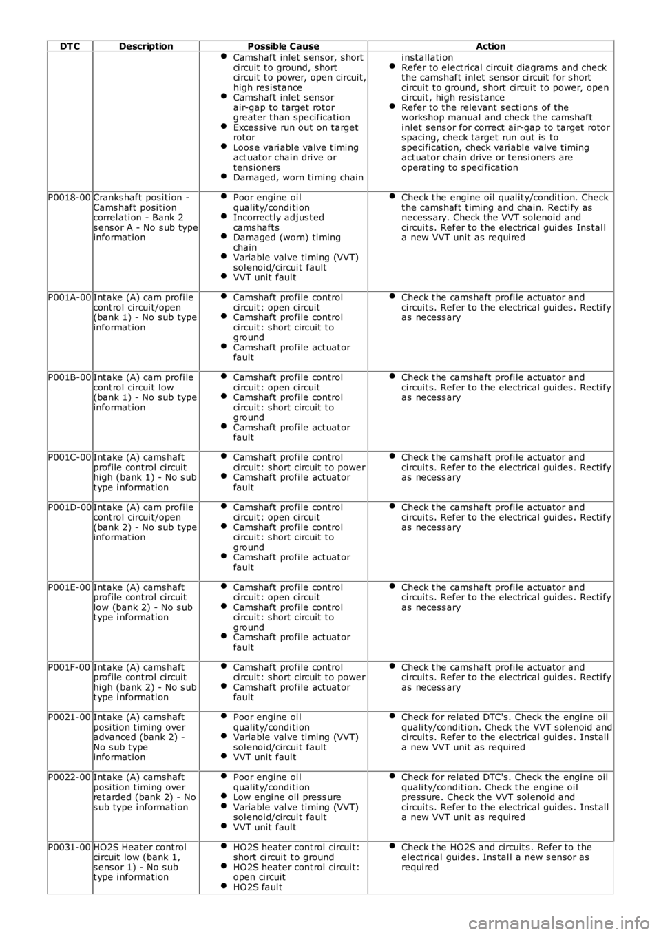
DT CDescriptionPossible CauseAction
Camshaft inlet s ensor, s hortci rcuit t o ground, s hortci rcuit t o power, open circui t,high res i st anceCamshaft inlet s ensorair-gap t o t arget rot orgreater t han specificati onExces si ve run out on t argetrot orLoos e vari abl e valve t imi ngact uat or chai n dri ve ortens ionersDamaged, worn ti mi ng chain
i nst all ati onRefer to el ect ri cal circui t diagrams and checkt he cams haft inl et sens or ci rcuit for s hortci rcuit t o ground, short ci rcuit t o power, openci rcuit , hi gh res is t anceRefer to t he relevant s ecti ons of t heworkshop manual and check t he camshafti nlet s ens or for correct ai r-gap to target rotors pacing, check target run out is tos pecifi cat ion, check vari abl e valve t imingact uat or chain drive or t ensi oners areoperat ing t o s peci fi cat ion
P0018-00Cranks haft pos i ti on -Cams haft posi ti oncorrel ati on - Bank 2s ens or A - No s ub typeinformat ion
Poor engine oi lqual it y/condi ti onIncorrect ly adjus t edcams haft sDamaged (worn) ti mingchainVariable val ve ti mi ng (VVT)sol enoi d/circui t faultVVT unit faul t
Check t he engi ne oil qual it y/condi ti on. Checkt he cams haft t imi ng and chai n. Recti fy asnecess ary. Check the VVT sol enoi d andci rcuit s. Refer t o t he electrical gui des Ins tal la new VVT unit as requi red
P001A-00Int ake (A) cam profi lecont rol circui t/open(bank 1) - No sub typeinformat ion
Camshaft profi le controlci rcuit : open ci rcuitCamshaft profi le controlci rcuit : s hort circuit t ogroundCamshaft profi le act uat orfault
Check t he cams haft profi le actuat or andci rcuit s. Refer t o t he electrical gui des . Recti fyas necess ary
P001B-00Int ake (A) cam profi lecont rol circui t low(bank 1) - No sub typeinformat ion
Camshaft profi le controlci rcuit : open ci rcuitCamshaft profi le controlci rcuit : s hort circuit t ogroundCamshaft profi le act uat orfault
Check t he cams haft profi le actuat or andci rcuit s. Refer t o t he electrical gui des . Recti fyas necess ary
P001C-00Int ake (A) cams haftprofile cont rol circuithigh (bank 1) - No s ubt ype i nformati on
Camshaft profi le controlci rcuit : s hort circuit t o powerCamshaft profi le act uat orfault
Check t he cams haft profi le actuat or andci rcuit s. Refer t o t he electrical gui des . Recti fyas necess ary
P001D-00Int ake (A) cam profi lecont rol circui t/open(bank 2) - No sub typeinformat ion
Camshaft profi le controlci rcuit : open ci rcuitCamshaft profi le controlci rcuit : s hort circuit t ogroundCamshaft profi le act uat orfault
Check t he cams haft profi le actuat or andci rcuit s. Refer t o t he electrical gui des . Recti fyas necess ary
P001E-00Int ake (A) cams haftprofile cont rol circuitlow (bank 2) - No s ubt ype i nformati on
Camshaft profi le controlci rcuit : open ci rcuitCamshaft profi le controlci rcuit : s hort circuit t ogroundCamshaft profi le act uat orfault
Check t he cams haft profi le actuat or andci rcuit s. Refer t o t he electrical gui des . Recti fyas necess ary
P001F-00Int ake (A) cams haftprofile cont rol circuithigh (bank 2) - No s ubt ype i nformati on
Camshaft profi le controlci rcuit : s hort circuit t o powerCamshaft profi le act uat orfault
Check t he cams haft profi le actuat or andci rcuit s. Refer t o t he electrical gui des . Recti fyas necess ary
P0021-00Int ake (A) cams haftposi ti on t imi ng overadvanced (bank 2) -No s ub t ypeinformat ion
Poor engine oi lqual it y/condi ti onVariable val ve ti mi ng (VVT)sol enoi d/circui t faultVVT unit faul t
Check for related DTC's. Check t he engi ne oilquali ty/condit ion. Check t he VVT s olenoid andci rcuit s. Refer t o t he electrical gui des . Inst alla new VVT unit as requi red
P0022-00Int ake (A) cams haftposi ti on t imi ng overret arded (bank 2) - Nos ub type i nformati on
Poor engine oi lqual it y/condi ti onLow engi ne oil pres s ureVariable val ve ti mi ng (VVT)sol enoi d/circui t faultVVT unit faul t
Check for related DTC's. Check t he engi ne oilquali ty/condit ion. Check t he engine oi lpress ure. Check the VVT sol enoi d andci rcuit s. Refer t o t he electrical gui des . Inst alla new VVT unit as requi red
P0031-00HO2S Heater controlcircuit low (bank 1,s ens or 1) - No s ubt ype i nformati on
HO2S heat er cont rol circui t:short ci rcuit t o groundHO2S heat er cont rol circui t:open ci rcuitHO2S faul t
Check t he HO2S and circuit s . Refer to theel ect ri cal guides . Ins tal l a new s ensor asrequi red
Page 603 of 3229
Publi s hed: 23-Aug-2011
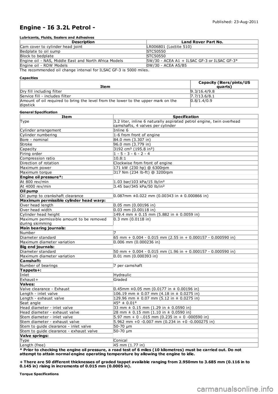
Engine - I6 3.2L Petrol -
Lubricants, Fluids, Sealers and AdhesivesDescriptionLand Rover Part No.
Cam cover to cyli nder head jointLR006801 (Loct it e 510)
Bedplate to oi l s umpSTC50550Block t o bedpl ateSTC50550
Engine oil - NAS, Mi ddl e Eas t and Nort h Africa Models5W /30 - ACEA A1 + ILSAC GF-3 or ILSAC GF-3*
Engine oil - ROW Models0W /30 - ACEA A5/B5The recommended oil change i nterval for ILSAC GF-3 is 5000 mi les .
C apacities
ItemCapacity (liters/pints/USquarts)
Dry fi ll i ncludi ng fi lt er9.3/16.4/9.8
Service fil l - includes fi lt er7.7/13.6/8.1Amount of oil required t o bri ng the level from the lower to the upper mark on thedips t ick0.8/1.4/0.9
General Specification
ItemSpecificationType3.2 li ter, inli ne 6 nat urall y aspi rat ed pet rol engine, twi n overheadcams haft s, 4 val ves per cylinderCyli nder arrangementInli ne 6
Cyli nder numberi ng1-6 from front of engine
Bore - nominal84.0 mm (3.307 in)St roke96.0 mm (3.779 in)
Capaci ty3192 cm³ (195.8 i n³)
Firing order1 - 5 - 3 - 6 - 2 - 4Compres s ion rati o10.8:1
Di recti on of rotat ionCl ockwis e from front of engi ne
Maximum power171 kW (230 hp) @ 6300rpmMaximum t orque317 Nm (234 lb-ft ) @ 3200rpm
Engine oil pressure*:
At 800 rev/min1.03 bar/103 kPa/15 lb/in²At 4000 rev/min3.45 bar/345 kPa/50 lb/in²
Oil pump
Oi l pump to cranks haft clearance0.087mm ±0.022 mm (0.00343 i n ± 0.000866 i n)Maximum permissible cylinder head w arp:
Over head length0.05 mm (0.00196 i n)
Over head widt h0.03 mm (0.00118 i n)Cyli nder head height149.4 mm ± 0.15 mm (5.882 in ± 0.0059 i n)
Maximum permi s si ble amount t o be removedduri ng s ki mmi ng0.3 mm (0.0118 in)
Main bearing journals:
Number7
Di amet er s tandard65 mm + 0.004 - 0.015 mm (2.55 in + 0.000157 - 0.000590 in)Maximum diamet er variat ion0.006 mm (0.000236 in)
Big end journals:
Di amet er s tandard50 mm + 0.004 - 0.015 mm (1.96 in + 0.000157 - 0.000590 in)Maximum diamet er variat ion0.01 mm (0.000393 i n)
Camshaft:
Number of bearings7 per cams haftT appets+:
InletHydrauli c
Exhaus t +GradedValves:
Valve clearance - Exhaus t0.45mm ±0.05 mm (0.0177 in ± 0.00196 in)
Lengt h - i nlet valve106.19 mm ± 0.07 mm (4.18 in ± 0.0275 i n)Lengt h - exhaus t valve129.96 mm ± 0.07 mm (5.12 in ± 0.0275 i n)
Seat angl e45° ± 0.01°
Head diamet er - inlet valve33 mm ± 0.15 mm (1.29 in ± 0.0590 i n)Head diamet er - exhaus t val ve28 mm ± 0.15 mm (1.10 in ± 0.0590 i n)
St em diamet er - inlet valve5.97 mm + 0 -.015 mm (0.235 in + 0 -000590 i n)
St em diamet er - exhaus t val ve5.962 mm +0 -0.007 mm (0.234 in +0 -0.000275 i n)St em t o guide clearance - i nlet val ve50-70 µm
St em t o guide clearance - exhaus t valve50-70 µm
Valve springs:TypeConical
Lengt h (free)45 mm (1.77 in)
* Prior to checking the engine oil pressure, a road test of 6 miles (10 kilometres) must be carried out. Do notattempt to attain normal engine operating temperature by allowing the engine to idle.
+ T here are 50 different thicknesses of graded tappet available ranging from 2.950mm to 3.685 mm (0.116 in to0.145 in) rising in increments of 0.015 mm (0.0005 in).
Torque Specifications
Page 632 of 3229
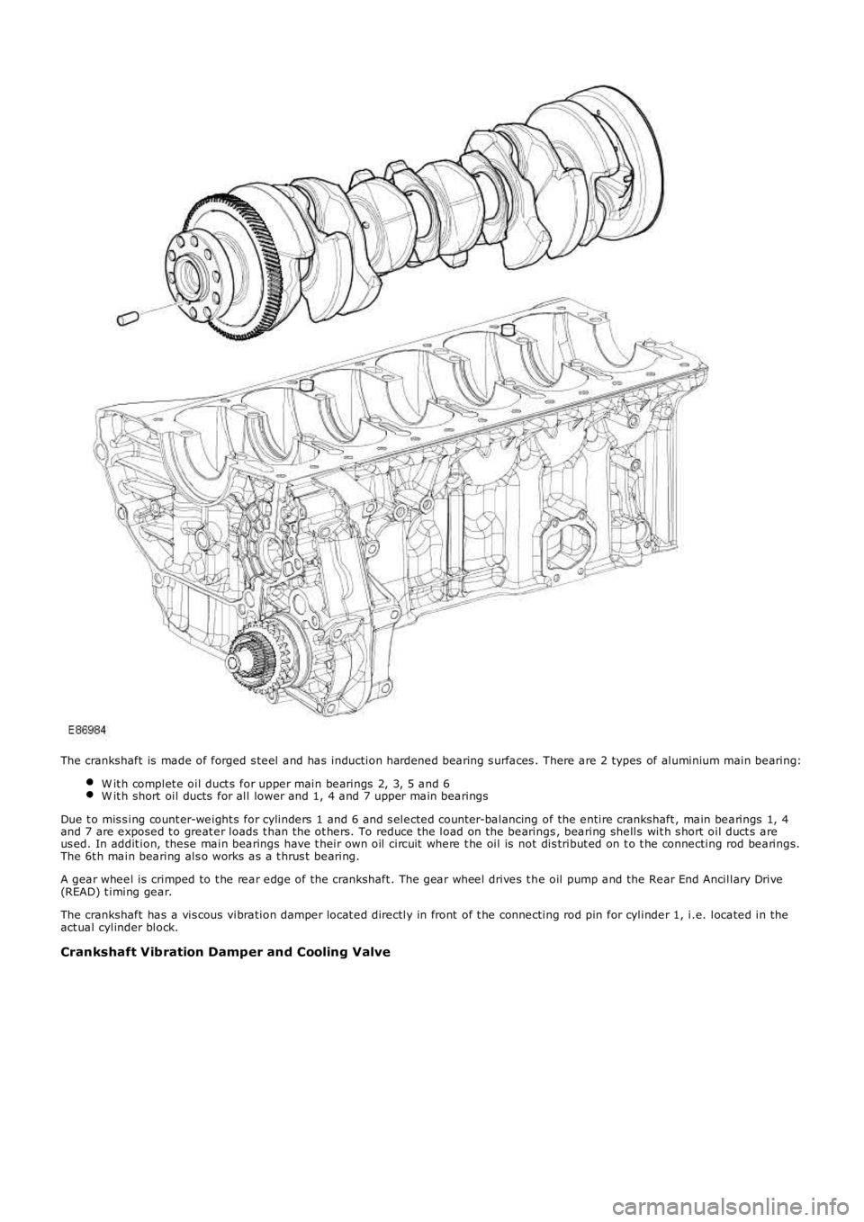
The crankshaft is made of forged s teel and has induction hardened bearing s urfaces . There are 2 types of aluminium main bearing:
W it h complet e oil duct s for upper main bearings 2, 3, 5 and 6W it h short oil ducts for all lower and 1, 4 and 7 upper main bearings
Due t o mis s ing count er-weight s for cylinders 1 and 6 and s elected count er-balancing of the entire crankshaft , main bearings 1, 4and 7 are exposed t o great er loads t han the ot hers. To reduce t he load on the bearings , bearing shells wit h s hort oil duct s areus ed. In addit ion, these main bearings have t heir own oil circuit where t he oil is not dis tribut ed on t o t he connecting rod bearings.The 6t h main bearing als o works as a t hrus t bearing.
A gear wheel is crimped to t he rear edge of the crankshaft . The gear wheel drives t he oil pump and the Rear End Ancillary Drive(READ) t iming gear.
The crankshaft has a vis cous vibration damper locat ed directly in front of t he connecting rod pin for cylinder 1, i.e. located in theact ual cylinder block.
Crankshaft Vibration Damper and Cooling Valve