2006 LAND ROVER FRELANDER 2 oil type
[x] Cancel search: oil typePage 752 of 3229
Publi s hed: 11-May-2011
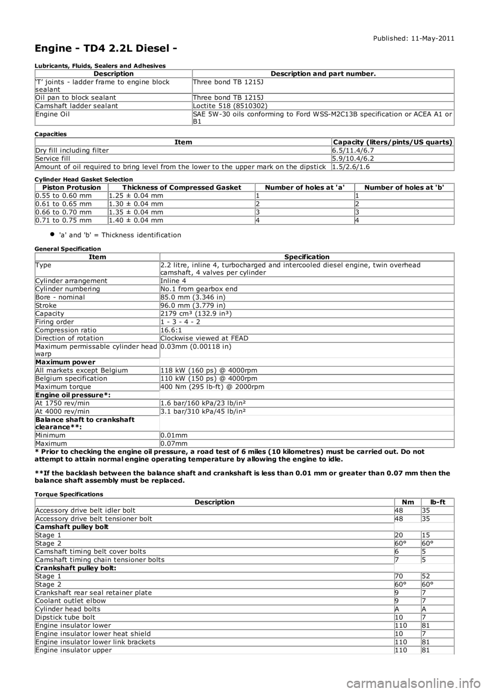
Engine - TD4 2.2L Diesel -
Lubricants, Fluids, Sealers and AdhesivesDescriptionDescription and part number.
‘T’ joi nts - ladder frame to engi ne blocks ealantThree bond TB 1215J
Oi l pan to bl ock s ealantThree bond TB 1215J
Cams haft l adder s eal antLocti te 518 (8510302)
Engine Oi lSAE 5W -30 oils conforming to Ford W SS-M2C13B specificat ion or ACEA A1 orB1
C apacities
ItemCapacity (liters/pints/US quarts)
Dry fi ll i ncludi ng fi lt er6.5/11.4/6.7Service fil l5.9/10.4/6.2
Amount of oil required t o bri ng level from t he lower t o t he upper mark on t he dips tick1.5/2.6/1.6
C ylinder Head Gasket Selection
Piston ProtusionT hickness of Compressed GasketNumber of holes at ' a'Number of holes at 'b'0.55 to 0.60 mm1.25 ± 0.04 mm11
0.61 to 0.65 mm1.30 ± 0.04 mm22
0.66 to 0.70 mm1.35 ± 0.04 mm330.71 to 0.75 mm1.40 ± 0.04 mm44
'a' and 'b' = Thi ckness identi fi cat ion
General Specification
ItemSpecificationType2.2 l it re, i nl ine 4, t urbocharged and int ercool ed dies el engine, t win overheadcamshaft , 4 valves per cyl inder
Cyli nder arrangementInl ine 4Cyli nder numberi ngNo.1 from gearbox end
Bore - nominal85.0 mm (3.346 i n)
St roke96.0 mm (3.779 i n)Capaci ty2179 cm³ (132.9 in³)
Firing order1 - 3 - 4 - 2
Compres s ion rati o16.6:1Di recti on of rotat ionClockwi s e viewed at FEAD
Maximum permi s sable cyl inder headwarp0.03mm (0.00118 i n)
Maximum pow er
All markets except Bel gi um118 kW (160 ps ) @ 4000rpmBelgi um s peci fi cat ion110 kW (150 ps ) @ 4000rpm
Maximum t orque400 Nm (295 l b-ft ) @ 2000rpm
Engine oil pressure*:At 1750 rev/min1.6 bar/160 kPa/23 l b/i n²
At 4000 rev/min3.1 bar/310 kPa/45 l b/i n²
Balance shaft to crankshaftclearance**:
Mi ni mum0.01mm
Maximum0.07mm* Prior to checking the engine oil pressure, a road test of 6 miles (10 kilometres) must be carried out. Do notattempt to attain normal engine operating temperature by allowing the engine to idle.
**If the backlash betw een the balance shaft and crankshaft is less than 0.01 mm or greater than 0.07 mm then thebalance shaft assembly must be replaced.
Torque SpecificationsDescriptionNmlb-ft
Acces s ory drive belt i dler bol t4835
Acces s ory drive belt t ensi oner bolt4835Camshaft pulley bolt
St age 12015
St age 260°60°Cams haft t imi ng belt cover bolt s65
Cams haft t imi ng chai n t ens ioner bolt s75
Crankshaft pulley bolt:St age 17052
St age 260°60°
Cranks haft rear s eal retai ner pl at e97Coolant outl et el bow97
Cyli nder head bolt sAA
Di ps t ick t ube bol t107Engine i ns ulat or lower11081
Engine i ns ulat or lower heat s hiel d107
Engine i ns ulat or lower li nk bracket s11081Engine i ns ulat or upper11081
Page 766 of 3229
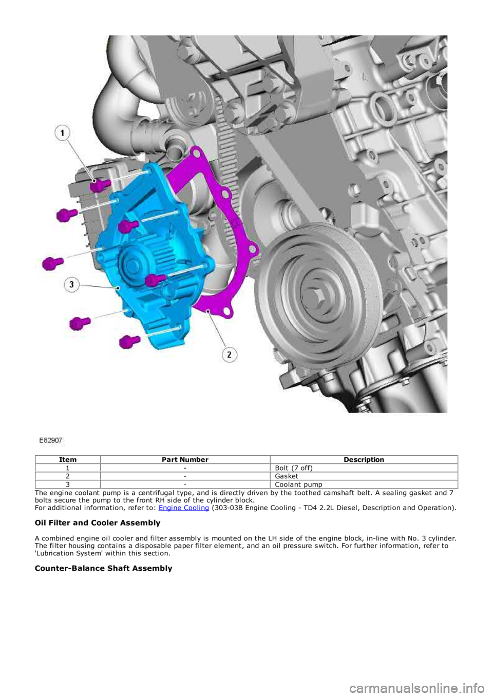
ItemPart NumberDescription
1-Bolt (7 off)2-Gas ket
3-Coolant pump
The engi ne cool ant pump is a cent ri fugal type, and is direct ly driven by t he t oot hed cams haft bel t. A s eal ing gas ket and 7bolt s s ecure the pump to the front RH si de of the cyli nder bl ock.For addit ional informat ion, refer t o: Engi ne Cooling (303-03B Engine Cooli ng - TD4 2.2L Dies el , Descripti on and Operat ion).
Oil Filter and Cooler Assembly
A combined engine oi l cooler and fil ter as sembl y is mount ed on t he LH s ide of t he engine block, in-line wit h No. 3 cylinder.The fi lt er hous ing contai ns a dis pos abl e paper fil ter element , and an oil pres s ure swi tch. For furt her i nformat ion, refer to'Lubri cat ion Sys tem' wi thin thi s s ect ion.
Counter-Balance Shaft Assembly
Page 772 of 3229
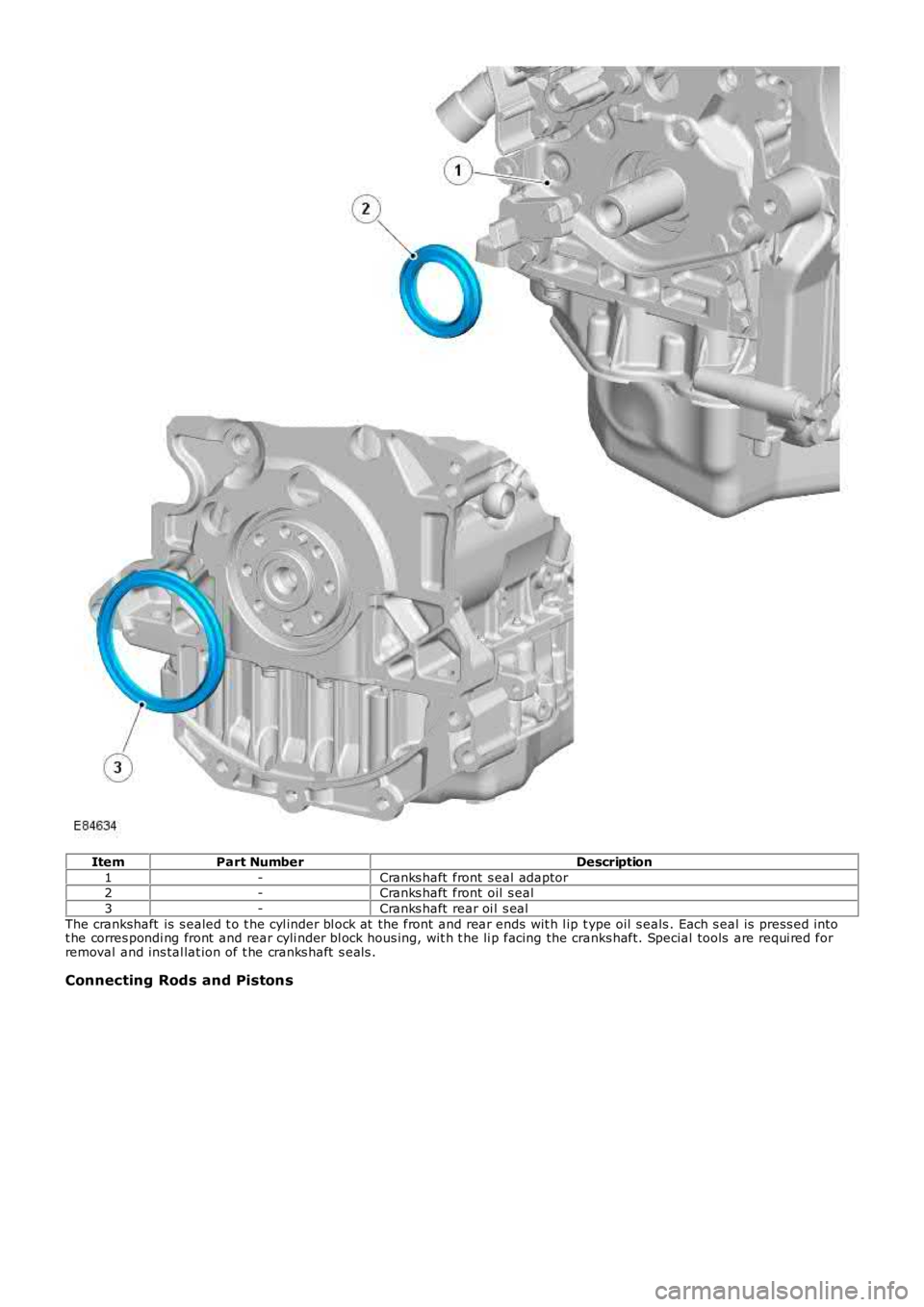
ItemPart NumberDescription
1-Cranks haft front s eal adaptor2-Cranks haft front oil s eal
3-Cranks haft rear oi l s eal
The crankshaft is s ealed t o t he cyl inder bl ock at the front and rear ends wit h l ip type oil s eals . Each s eal is press ed i ntot he corres pondi ng front and rear cyli nder bl ock hous ing, wit h t he li p facing the cranks haft. Special tools are requi red forremoval and ins tal lat ion of t he cranks haft s eals .
Connecting Rods and Pistons
Page 775 of 3229
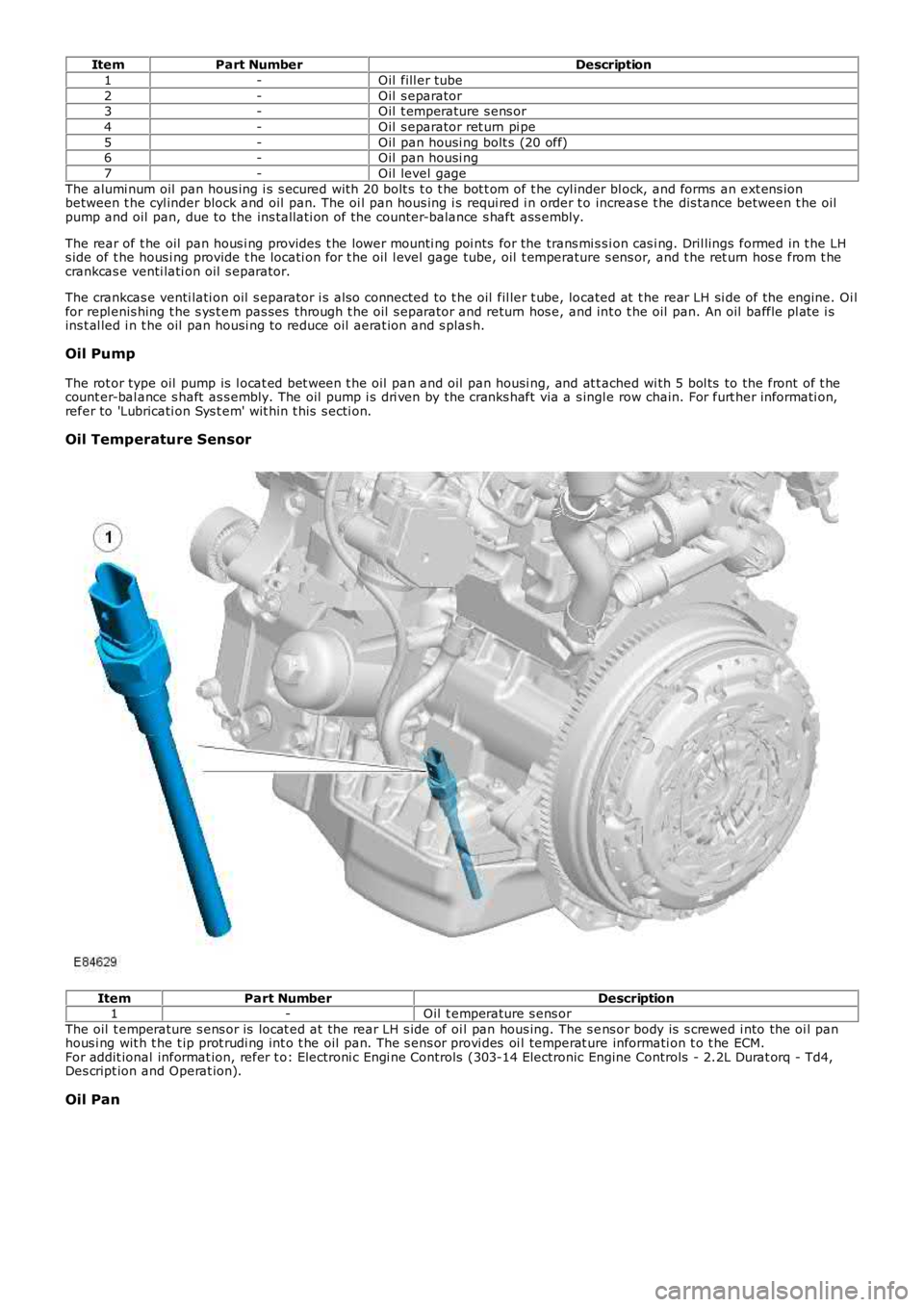
ItemPart NumberDescription
1-Oil fill er tube
2-Oil s eparator3-Oil t emperature s ens or
4-Oil s eparator ret urn pi pe
5-Oil pan housi ng bolt s (20 off)6-Oil pan housi ng
7-Oil level gage
The alumi num oil pan hous ing i s s ecured wit h 20 bolt s t o t he bot t om of t he cyl inder bl ock, and forms an ext ens ionbetween t he cyl inder block and oil pan. The oi l pan hous ing i s requi red i n order t o increas e t he dis tance between t he oilpump and oil pan, due to the ins tall ati on of the counter-balance s haft ass embly.
The rear of t he oil pan hous i ng provides t he lower mounti ng poi nts for the trans mi s si on cas i ng. Dril lings formed in t he LHs ide of t he hous i ng provide t he locati on for t he oil l evel gage tube, oil t emperature s ens or, and t he ret urn hos e from t hecrankcas e venti lati on oil s eparator.
The crankcas e venti lati on oil s eparator i s als o connected to t he oil fil ler t ube, located at t he rear LH si de of the engine. Oi lfor repl enis hing t he s ys t em pas ses through t he oil s eparator and return hos e, and int o t he oil pan. An oil baffle pl ate i sins t al led i n t he oil pan housi ng to reduce oil aerat ion and s plas h.
Oil Pump
The rot or type oil pump is l ocat ed bet ween t he oil pan and oil pan housi ng, and at t ached wi th 5 bol ts to the front of t hecount er-bal ance s haft as s embly. The oil pump i s dri ven by the cranks haft via a s ingle row chain. For furt her informati on,refer to 'Lubricati on Sys t em' wit hin t his s ecti on.
Oil Temperature Sensor
ItemPart NumberDescription1-Oil t emperature s ens or
The oil t emperature s ens or is locat ed at t he rear LH s ide of oi l pan hous ing. The s ens or body is s crewed i nto the oi l panhous i ng wit h t he t ip prot rudi ng int o t he oil pan. The s ens or provi des oi l temperat ure informati on t o t he ECM.For addit ional informat ion, refer t o: Electroni c Engi ne Controls (303-14 Electronic Engine Controls - 2.2L Durat orq - Td4,Des cript ion and Operat ion).
Oil Pan
Page 776 of 3229
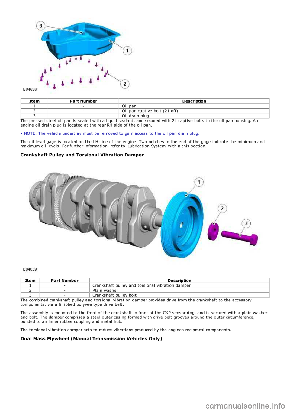
ItemPart NumberDescription
1-Oil pan2-Oil pan capti ve bol t (21 off)
3-Oil drai n plug
The pres s ed s teel oil pan is sealed wit h a l iquid sealant , and secured wi th 21 capt ive bolt s t o t he oil pan housi ng. Anengi ne oil drai n plug is l ocat ed at the rear RH s ide of t he oil pan.
• NOTE: The vehi cle undert ray mus t be removed to gai n acces s t o t he oil pan drain plug.
The oil l evel gage is l ocat ed on t he LH s ide of t he engi ne. Two not ches in t he end of t he gage indicate t he mi nimum andmaximum oil l evels . For further informat ion, refer t o 'Lubricat ion Sys t em' wit hi n t his s ect ion.
Crankshaft Pulley and Torsional Vibration Damper
ItemPart NumberDescription
1-Cranks haft pull ey and torsi onal vibrat ion damper
2-Plai n was her3-Cranks haft pull ey bol t
The combined crankshaft pul ley and t ors ional vi brat ion damper provides dri ve from t he crankshaft to the acces s orycomponents , via a 6 ribbed polyvee type drive belt .
The as sembl y is mount ed t o t he front of t he crankshaft in front of t he CKP s ens or ring, and i s s ecured wit h a pl ain was herand bolt . The damper compri ses a s teel out er cas i ng formed wit h drive belt grooves around t he outer circumference,bonded t o an inner rubber coupl ing and metal hub.
The t ors ional vi brati on damper act s to reduce vibrat ions produced by the engines reci procal component s .
Dual Mass Flywheel (Manual Transmission Vehicles Only)
Page 784 of 3229
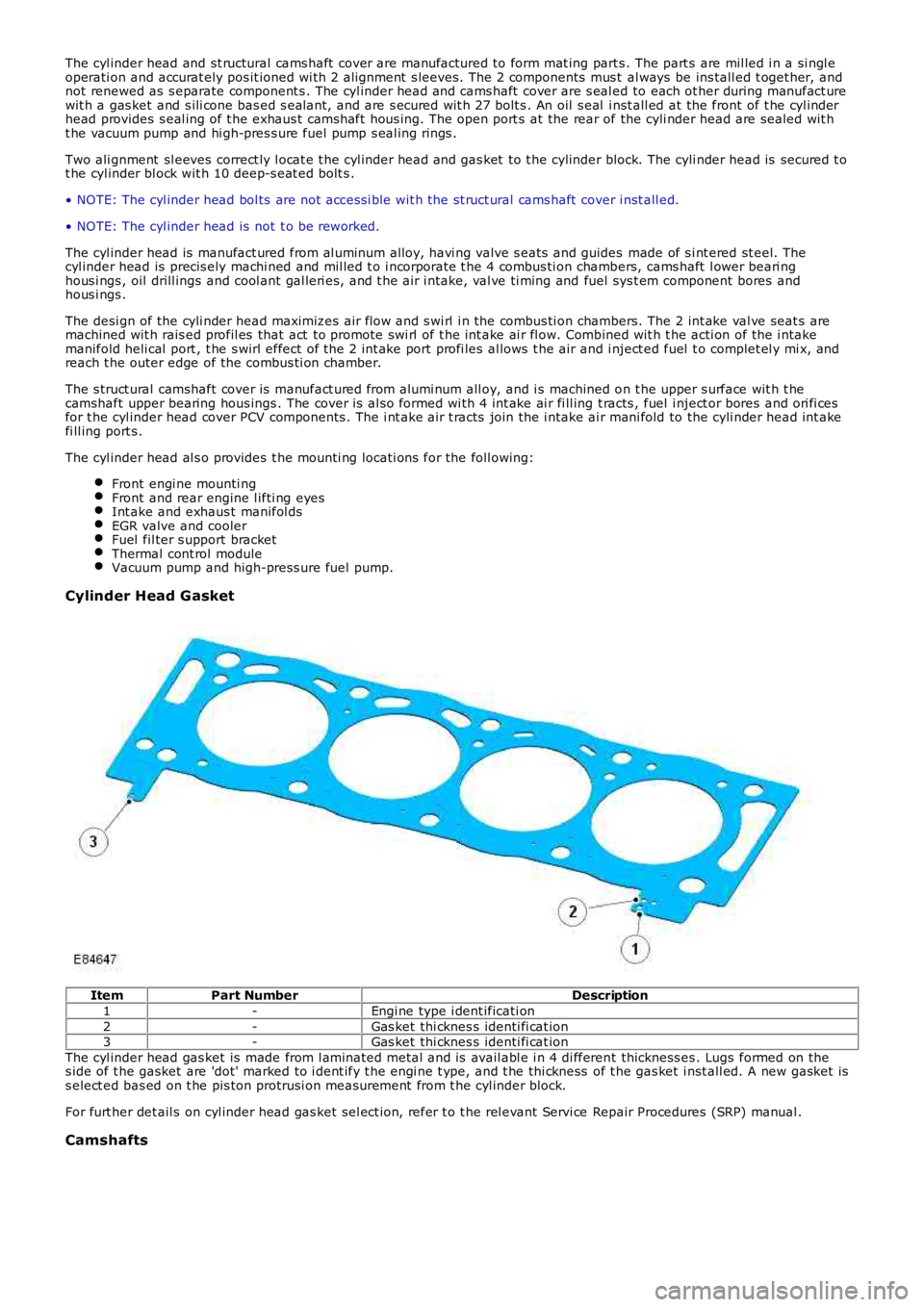
The cyl inder head and st ructural cams haft cover are manufactured to form mat ing parts . The part s are mil led i n a si ngl eoperati on and accurat ely pos it ioned wi th 2 alignment s leeves. The 2 components mus t al ways be ins tall ed t oget her, andnot renewed as s eparate component s . The cyl inder head and cams haft cover are s eal ed to each ot her during manufact urewit h a gas ket and s ili cone bas ed s eal ant, and are s ecured wit h 27 bolt s . An oil s eal i nst all ed at the front of t he cyl inderhead provides s eal ing of t he exhaus t camshaft hous ing. The open port s at the rear of the cyli nder head are sealed wit ht he vacuum pump and hi gh-pres s ure fuel pump s eal ing rings .
Two ali gnment sl eeves correct ly l ocat e t he cyl inder head and gas ket to t he cylinder block. The cyli nder head is secured t ot he cyl inder bl ock wit h 10 deep-s eat ed bolt s .
• NOTE: The cyl inder head bol ts are not acces si ble wit h the st ruct ural cams haft cover i nst all ed.
• NOTE: The cyl inder head is not t o be reworked.
The cyl inder head is manufact ured from al uminum alloy, havi ng valve s eats and guides made of s i nt ered st eel. Thecyl inder head is precis ely machi ned and mil led t o i ncorporate t he 4 combus ti on chambers, cams haft l ower beari nghous i ngs , oil drill ings and cool ant gal leri es, and t he air i ntake, val ve ti ming and fuel sys t em component bores andhous i ngs .
The desi gn of the cyli nder head maximizes air flow and s wi rl i n the combus ti on chambers. The 2 int ake val ve seat s aremachined wit h rais ed profil es that act to promote swi rl of t he int ake ai r fl ow. Combined wit h t he acti on of the i ntakemanifold heli cal port , t he s wirl effect of the 2 int ake port profi les al lows t he air and i nject ed fuel t o complet el y mi x, andreach t he outer edge of the combus ti on chamber.
The s truct ural camshaft cover is manufact ured from alumi num all oy, and i s machined on t he upper s urface wit h t hecamshaft upper bearing hous ings . The cover is al so formed wi th 4 int ake ai r fi ll ing t racts , fuel i nject or bores and ori fi cesfor t he cyl inder head cover PCV components . The i nt ake air t racts join the i ntake air mani fold to the cyli nder head int akefi ll ing port s .
The cyl inder head al s o provides t he mounti ng locati ons for the foll owing:
Front engi ne mounti ngFront and rear engine l ifti ng eyesInt ake and exhaus t manifol dsEGR valve and coolerFuel fil ter s upport bracketThermal cont rol moduleVacuum pump and high-press ure fuel pump.
Cylinder Head G asket
ItemPart NumberDescription
1-Engi ne type i dent ificati on
2-Gas ket thi cknes s identi fi cat ion3-Gas ket thi cknes s identi fi cat ion
The cyl inder head gas ket is made from l aminated metal and is avail abl e i n 4 di fferent thickness es . Lugs formed on thes ide of t he gasket are 'dot' marked to i dent ify t he engi ne t ype, and t he thi ckness of t he gas ket i nst all ed. A new gasket iss elect ed bas ed on t he pis ton protrusi on meas urement from t he cyl inder block.
For furt her det ail s on cyl inder head gas ket sel ect ion, refer t o t he rel evant Servi ce Repair Procedures (SRP) manual .
Camshafts
Page 788 of 3229
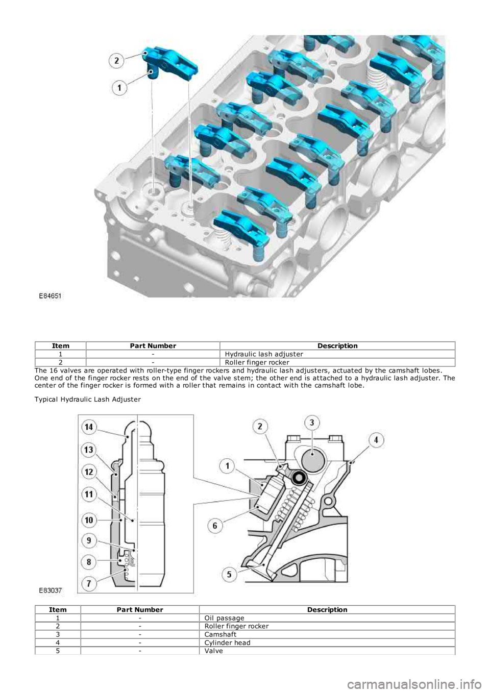
ItemPart NumberDescription
1-Hydrauli c las h adjus t er
2-Roll er fi nger rockerThe 16 valves are operat ed wi th roll er-type finger rockers and hydraulic las h adjus ters, actuat ed by the cams haft l obes .One end of t he fi nger rocker res ts on the end of t he valve s t em; the ot her end is attached to a hydraulic las h adjus ter. Thecent er of the finger rocker i s formed wi th a rol ler t hat remains i n cont act wit h the cams haft l obe.
Typi cal Hydrauli c Lash Adjust er
ItemPart NumberDescription
1-Oil pass age2-Rol ler finger rocker
3-Camshaft
4-Cyl inder head5-Val ve
Page 799 of 3229
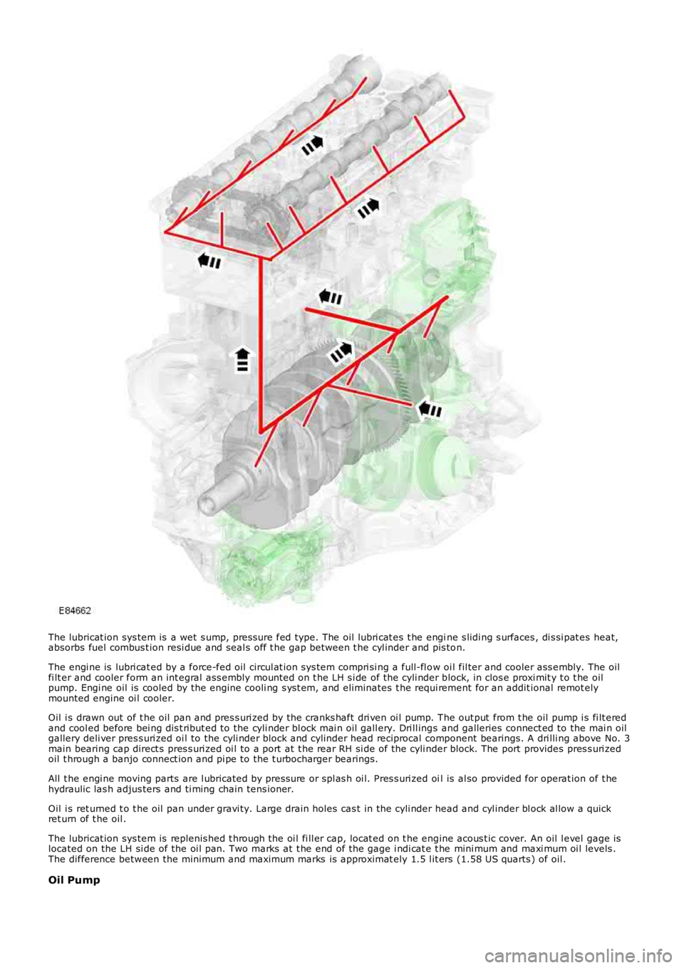
The lubricat ion sys tem is a wet s ump, pres sure fed type. The oil lubri cat es t he engine s lidi ng s urfaces , di s si pat es heat,absorbs fuel combus t ion resi due and seal s off t he gap between t he cyl inder and pis ton.
The engi ne is lubri cat ed by a force-fed oil circul at ion sys tem compri si ng a full-fl ow oi l fil ter and cooler ass embly. The oilfi lt er and cooler form an int egral ass embly mount ed on t he LH s i de of the cyli nder block, in clos e proxi mit y t o t he oilpump. Engi ne oil is cooled by the engine cooli ng s ys t em, and eliminates t he requi rement for an addit ional remot elymounted engine oi l cooler.
Oil i s drawn out of t he oil pan and pres s uri zed by the cranks haft dri ven oi l pump. The out put from t he oil pump i s fi lt eredand cool ed before bei ng dis t ribut ed to the cyli nder bl ock mai n oil gall ery. Dri ll ings and galleries connect ed to the mai n oilgallery deli ver pres s uri zed oi l to the cyli nder block and cyl inder head reciprocal component bearings. A dri lli ng above No. 3main bearing cap direct s pres s uri zed oi l to a port at t he rear RH si de of the cyli nder block. The port provides pres s uri zedoil t hrough a banjo connect ion and pi pe to the t urbocharger bearings.
All t he engi ne moving parts are l ubricated by press ure or spl as h oi l. Pres s uri zed oil is al so provided for operat ion of t hehydraulic las h adjus ters and ti ming chain tens ioner.
Oil i s ret urned t o t he oil pan under gravi ty. Large drain holes cas t in the cyli nder head and cyl inder bl ock al low a quickret urn of t he oil .
The lubricat ion sys tem is replenis hed t hrough the oi l fi ll er cap, locat ed on t he engine acous t ic cover. An oil l evel gage islocated on the LH si de of the oi l pan. Two marks at t he end of the gage i ndi cat e t he mini mum and maxi mum oi l levels .The difference between the minimum and maximum marks is approximat ely 1.5 l it ers (1.58 US quarts ) of oil .
Oil Pump