2006 LAND ROVER FRELANDER 2 oil type
[x] Cancel search: oil typePage 1195 of 3229
Publi s hed: 11-May-2011
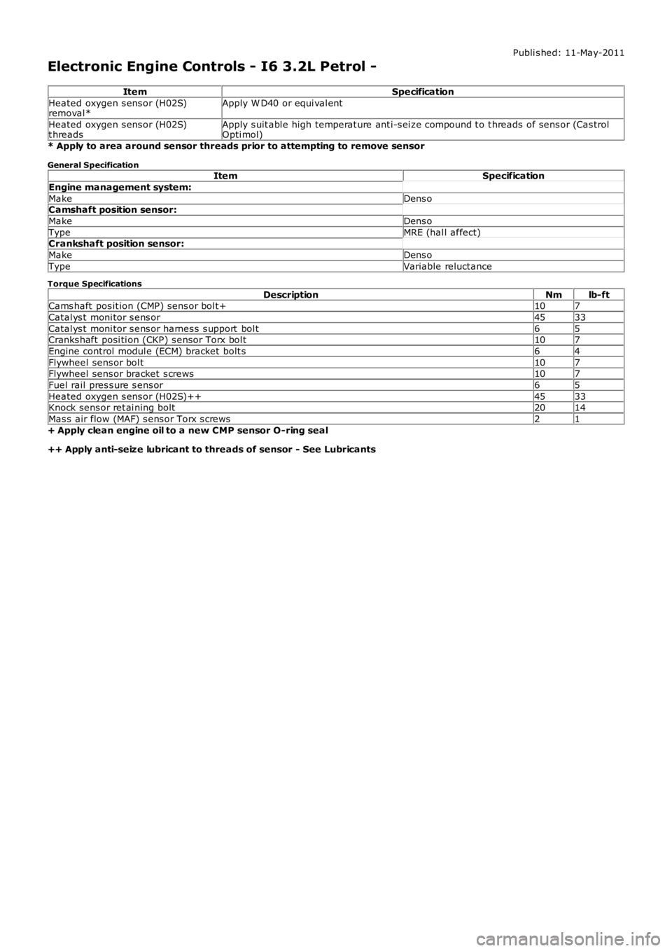
Electronic Engine Controls - I6 3.2L Petrol -
ItemSpecification
Heated oxygen s ens or (H02S)removal *Apply W D40 or equi val ent
Heated oxygen s ens or (H02S)t hreadsApply s uit abl e high temperat ure ant i-s ei ze compound t o t hreads of sens or (Cas trolOpti mol)
* Apply to area around sensor threads prior to attempting to remove sensor
General SpecificationItemSpecification
Engine management system:
MakeDens oCamshaft position sensor:
MakeDens o
TypeMRE (hal l affect)Crankshaft position sensor:
MakeDens o
TypeVariable reluctance
Torque Specifications
DescriptionNmlb-ftCams haft pos it ion (CMP) sens or bol t+107
Catal ys t moni tor s ens or4533
Catal ys t moni tor s ens or harnes s s upport bol t65Cranks haft posi ti on (CKP) s ensor Torx bol t107
Engine control modul e (ECM) bracket bolt s64
Flywheel sens or bol t107Flywheel sens or bracket s crews107
Fuel rail pres s ure s ens or65
Heated oxygen s ens or (H02S)++4533Knock sens or ret ai ning bolt2014
Mas s air flow (MAF) s ens or Torx s crews21
+ Apply clean engine oil to a new CMP sensor O-ring seal
++ Apply anti-seize lubricant to threads of sensor - See Lubricants
Page 1206 of 3229
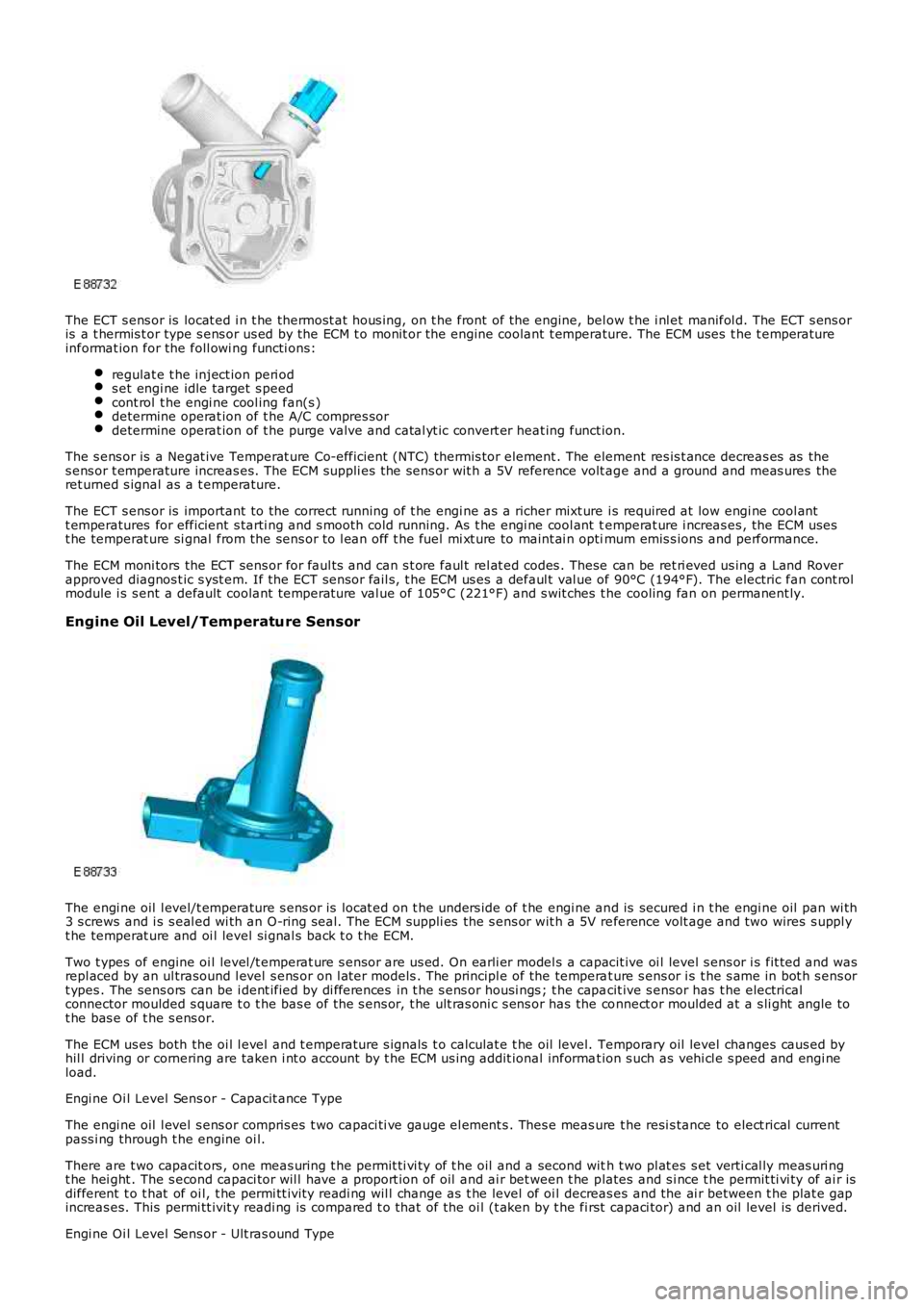
The ECT s ens or is locat ed i n t he thermost at hous ing, on t he front of the engine, below t he i nl et manifol d. The ECT s ens oris a t hermis t or type s ens or us ed by the ECM t o monit or the engine coolant t emperature. The ECM uses t he t emperatureinformat ion for the foll owi ng functi ons:
regulat e t he inject ion peri ods et engi ne idle target s peedcont rol t he engi ne cool ing fan(s )determine operat ion of t he A/C compres sordetermine operat ion of t he purge valve and catal yt ic convert er heat ing funct ion.
The s ens or is a Negat ive Temperat ure Co-efficient (NTC) thermis tor element . The element res is t ance decreas es as thes ens or t emperature increas es. The ECM suppli es the sens or wit h a 5V reference volt age and a ground and meas ures theret urned s ignal as a t emperature.
The ECT s ens or is important to the correct running of t he engi ne as a richer mixt ure i s required at low engi ne cool antt emperatures for efficient s tarti ng and s mooth cold running. As t he engi ne cool ant temperat ure i ncreas es , the ECM usest he temperat ure si gnal from the sens or to l ean off t he fuel mi xt ure to maint ai n optimum emis s ions and performance.
The ECM moni tors the ECT sens or for faul ts and can s t ore faul t rel at ed codes . These can be ret ri eved us ing a Land Roverapproved diagnos t ic s yst em. If the ECT sens or fail s, t he ECM us es a defaul t val ue of 90°C (194°F). The electric fan cont rolmodule i s s ent a default coolant temperat ure val ue of 105°C (221°F) and s wit ches t he cooling fan on permanent ly.
Engine Oil Level/Temperature Sensor
The engi ne oil l evel/t emperature s ens or is locat ed on t he unders ide of t he engi ne and is secured i n t he engi ne oil pan wi th3 s crews and i s s eal ed wi th an O-ring s eal. The ECM suppli es the s ens or wit h a 5V reference volt age and two wires s uppl yt he temperat ure and oi l level si gnal s back t o t he ECM.
Two t ypes of engine oi l level /t emperat ure s ensor are us ed. On earli er model s a capacit ive oi l level s ens or i s fit ted and wasrepl aced by an ul trasound l evel s ens or on l at er models . The principl e of the temperat ure s ens or i s t he s ame in bot h s ens ort ypes . The sens ors can be i dent ified by di fferences in t he s ens or housi ngs ; t he capacit ive s ensor has t he electricalconnector moulded s quare t o t he bas e of the s ens or, t he ult ras oni c s ens or has the connect or moulded at a s li ght angle tot he bas e of t he s ens or.
The ECM us es both the oi l l evel and t emperature s ignals t o calculat e t he oil level. Temporary oil level changes caus ed byhil l driving or cornering are taken i nt o account by t he ECM us ing addit ional informat ion s uch as vehi cl e s peed and engi neload.
Engi ne Oi l Level Sens or - Capacit ance Type
The engi ne oil l evel s ens or compris es t wo capaci ti ve gauge el ement s . Thes e meas ure the resi s tance to elect rical currentpass i ng through t he engine oi l.
There are t wo capacit ors , one meas uring t he permit ti vi ty of t he oil and a second with t wo pl at es s et verti cal ly meas uri ngt he hei ght . The s econd capaci tor wil l have a proport ion of oil and ai r bet ween t he plates and s i nce t he permit ti vi ty of ai r isdifferent t o t hat of oi l, t he permi tt ivit y readi ng wil l change as t he level of oi l decreas es and the ai r between t he plat e gapincreas es. This permi tt ivit y readi ng is compared t o t hat of the oi l (t aken by t he first capaci tor) and an oil level is derived.
Engi ne Oi l Level Sens or - Ult ras ound Type
Page 1207 of 3229
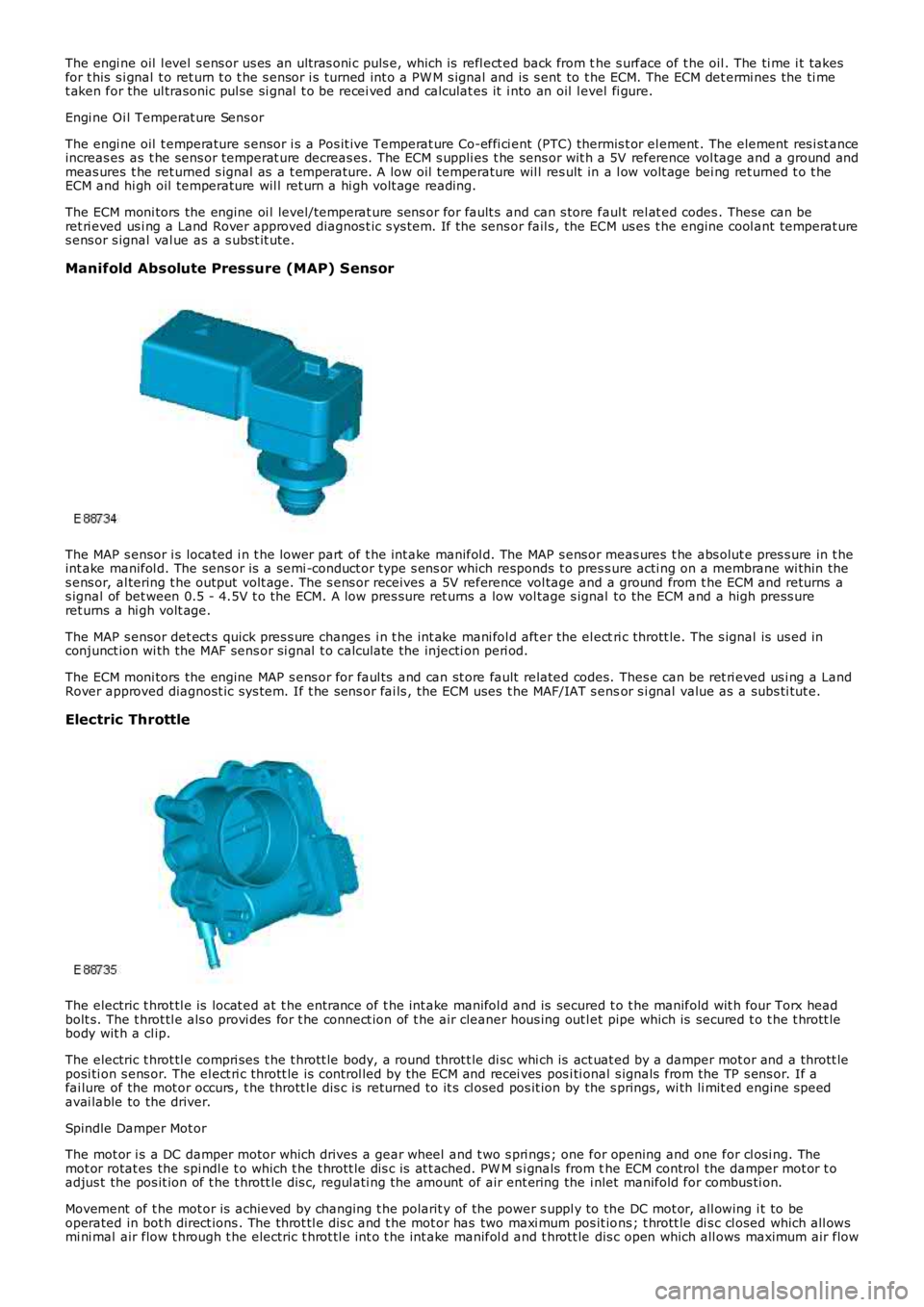
The engi ne oil l evel s ens or us es an ult ras oni c puls e, which is refl ect ed back from the s urface of t he oil . The ti me i t takesfor t his s i gnal t o ret urn t o t he s ensor i s turned int o a PW M s ignal and is s ent to the ECM. The ECM det ermi nes the ti met aken for the ul trasonic pul se si gnal t o be recei ved and calculat es it i nto an oil level fi gure.
Engi ne Oi l Temperat ure Sens or
The engi ne oil t emperature s ensor i s a Pos it ive Temperat ure Co-effi ci ent (PTC) thermis t or el ement . The element res i st anceincreas es as t he sens or temperat ure decreas es. The ECM s uppli es t he sens or wit h a 5V reference vol tage and a ground andmeas ures t he ret urned s ignal as a t emperature. A low oil temperature wil l res ult in a l ow volt age bei ng ret urned t o t heECM and hi gh oil temperature wil l ret urn a hi gh volt age reading.
The ECM moni tors the engine oi l level/temperat ure sens or for fault s and can s tore faul t rel at ed codes . These can beret ri eved us i ng a Land Rover approved diagnos t ic s ys tem. If the sens or fail s , the ECM us es t he engine cool ant temperat ures ens or s ignal val ue as a s ubst it ute.
Manifold Absolute Pressure (MAP) Sensor
The MAP s ensor i s located i n t he lower part of t he int ake manifol d. The MAP s ens or meas ures t he abs olut e pres s ure in t heint ake manifol d. The sens or is a semi -conduct or type s ens or which responds t o pres s ure acti ng on a membrane wi thin thes ens or, al tering t he output volt age. The s ens or receives a 5V reference vol tage and a ground from t he ECM and returns as ignal of bet ween 0.5 - 4.5V t o t he ECM. A low pres sure ret urns a low vol tage s ignal to the ECM and a high press ureret urns a hi gh volt age.
The MAP s ensor det ect s quick pres s ure changes i n t he int ake mani fol d aft er the el ectri c thrott le. The s ignal is us ed inconjunct ion wi th the MAF sens or si gnal t o calculate the injecti on peri od.
The ECM moni tors the engine MAP s ens or for faul ts and can st ore fault related codes. Thes e can be ret ri eved us i ng a LandRover approved diagnost ic sys tem. If t he s ens or fai ls , the ECM uses t he MAF/IAT s ensor s i gnal value as a subs ti tut e.
Electric Throttle
The electric t hrot tl e is locat ed at t he entrance of t he int ake manifol d and is secured t o t he manifold wit h four Torx headbolt s. The t hrot tl e als o provi des for t he connect ion of t he air cleaner hous ing out let pipe which is secured t o t he t hrott lebody wit h a cl ip.
The electric t hrot tl e compri ses t he t hrott le body, a round throt t le di sc whi ch is act uat ed by a damper mot or and a thrott leposi ti on s ens or. The el ect ri c thrott le is control led by the ECM and recei ves pos i ti onal s ignals from the TP s ens or. If afai lure of the mot or occurs , t he thrott le di s c is returned to it s cl osed pos it ion by the s prings, wi th li mit ed engine s peedavai lable to the driver.
Spindle Damper Mot or
The mot or i s a DC damper motor which drives a gear wheel and t wo s pri ngs ; one for opening and one for cl osi ng. Themot or rotat es the spi ndl e t o which t he t hrott le dis c is at t ached. PW M s i gnals from the ECM control the damper mot or t oadjus t the pos it ion of t he t hrott le dis c, regul ati ng the amount of air ent ering the i nlet manifold for combus ti on.
Movement of t he mot or is achieved by changing t he polarit y of the power s uppl y to the DC mot or, all owing i t to beoperated in bot h direct ions . The throt tl e dis c and t he mot or has two maxi mum pos it ions ; t hrott le di s c cl osed which all owsmi ni mal air flow t hrough t he electric t hrot tl e int o t he int ake manifol d and t hrott le dis c open which all ows maximum air flow
Page 1237 of 3229
Publi s hed: 11-May-2011
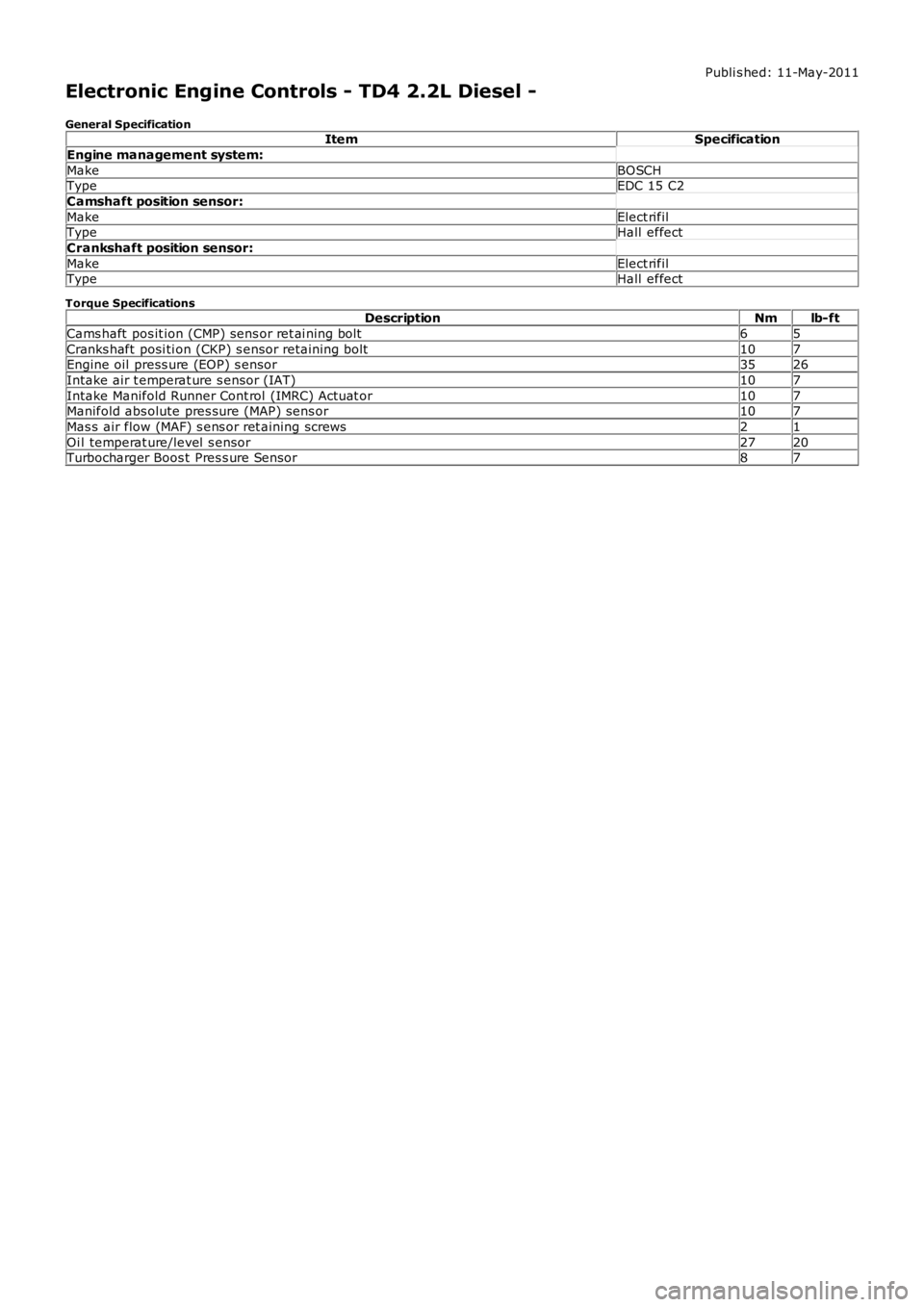
Electronic Engine Controls - TD4 2.2L Diesel -
General SpecificationItemSpecification
Engine management system:
MakeBOSCHTypeEDC 15 C2
Camshaft position sensor:
MakeElect rifilTypeHall effect
Crankshaft position sensor:
MakeElect rifilTypeHall effect
Torque SpecificationsDescriptionNmlb-ft
Cams haft pos it ion (CMP) sens or ret ai ning bolt65
Cranks haft posi ti on (CKP) s ensor retaini ng bolt107Engine oil press ure (EOP) s ensor3526
Intake air t emperat ure s ensor (IAT)107
Intake Manifold Runner Cont rol (IMRC) Actuat or107Manifold abs olute pres sure (MAP) sens or107
Mas s air flow (MAF) s ens or ret aining screws21
Oi l temperat ure/level s ensor2720Turbocharger Boos t Pres s ure Sensor87
Page 1277 of 3229
Publi s hed: 11-May-2011
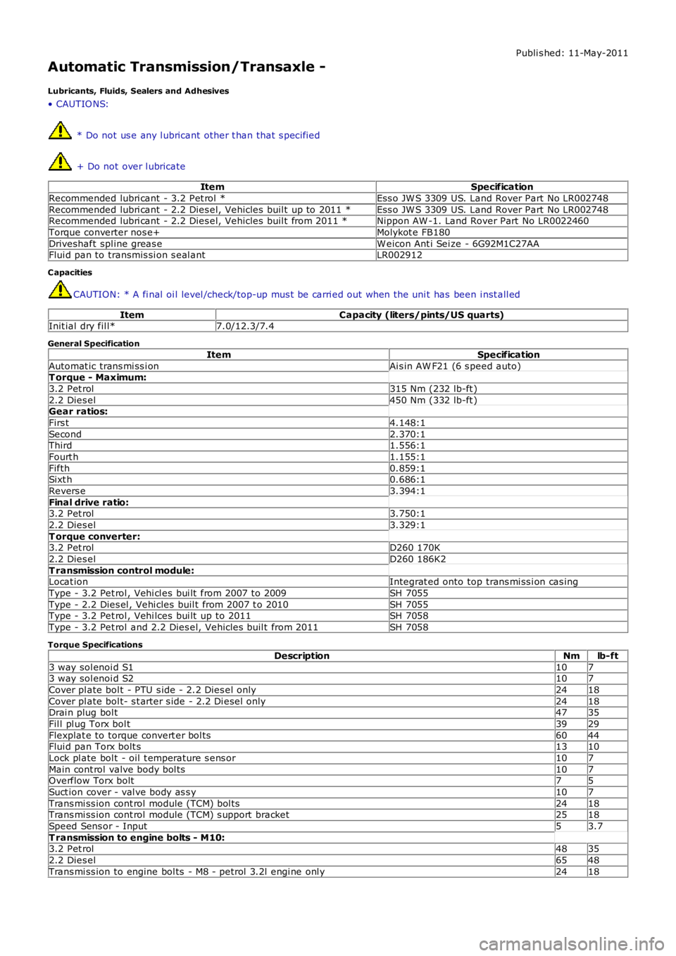
Automatic Transmission/Transaxle -
Lubricants, Fluids, Sealers and Adhesives
• CAUTIO NS:
* Do not us e any l ubricant other t han that s pecified
+ Do not over l ubricate
ItemSpecification
Recommended lubri cant - 3.2 Pet rol *Ess o JW S 3309 US. Land Rover Part No LR002748
Recommended lubri cant - 2.2 Dies el, Vehicles buil t up to 2011 *Ess o JW S 3309 US. Land Rover Part No LR002748Recommended lubri cant - 2.2 Dies el, Vehicles buil t from 2011 *Nippon AW -1. Land Rover Part No LR0022460
Torque converter nos e+Molykot e FB180
Driveshaft spl ine greas eW eicon Ant i Sei ze - 6G92M1C27AAFlui d pan to transmis si on s eal antLR002912
C apacities
CAUTION: * A fi nal oi l level /check/top-up mus t be carri ed out when the uni t has been i nst all ed
ItemCapacity (liters/pints/US quarts)Init ial dry fil l*7.0/12.3/7.4
General Specification
ItemSpecification
Automat ic trans mi ss i onAi s in AW F21 (6 s peed auto)T orque - Maximum:
3.2 Pet rol315 Nm (232 lb-ft )
2.2 Dies el450 Nm (332 lb-ft )Gear ratios:
Firs t4.148:1
Second2.370:1Third1.556:1
Fourt h1.155:1
Fifth0.859:1Sixt h0.686:1
Revers e3.394:1
Final drive ratio:3.2 Pet rol3.750:1
2.2 Dies el3.329:1
T orque converter:3.2 Pet rolD260 170K
2.2 Dies elD260 186K2
T ransmission control module:Locat ionIntegrat ed onto top trans mi ss i on cas ing
Type - 3.2 Pet rol , Vehi cl es bui lt from 2007 to 2009SH 7055
Type - 2.2 Dies el , Vehi cles buil t from 2007 t o 2010SH 7055Type - 3.2 Pet rol , Vehi lces bui lt up to 2011SH 7058
Type - 3.2 Pet rol and 2.2 Dies el, Vehicles buil t from 2011SH 7058
Torque Specifications
DescriptionNmlb-ft
3 way sol enoi d S11073 way sol enoi d S2107
Cover pl ate bol t - PTU s ide - 2.2 Dies el onl y2418
Cover pl ate bol t- s t arter s ide - 2.2 Di esel only2418Drai n plug bol t4735
Fil l pl ug Torx bol t3929
Flexplat e to torque convert er bol ts6044Flui d pan Torx bolt s1310
Lock pl ate bol t - oil t emperature s ens or107
Main cont rol valve body bol ts107Overflow Torx bolt75
Suct ion cover - val ve body as s y107
Trans mi ss ion cont rol module (TCM) bol ts2418Trans mi ss ion cont rol module (TCM) s upport bracket2518
Speed Sens or - Input53.7
T ransmission to engine bolts - M10:3.2 Pet rol4835
2.2 Dies el6548
Trans mi ss ion to engine bol ts - M8 - petrol 3.2l engi ne onl y2418
Page 2480 of 3229
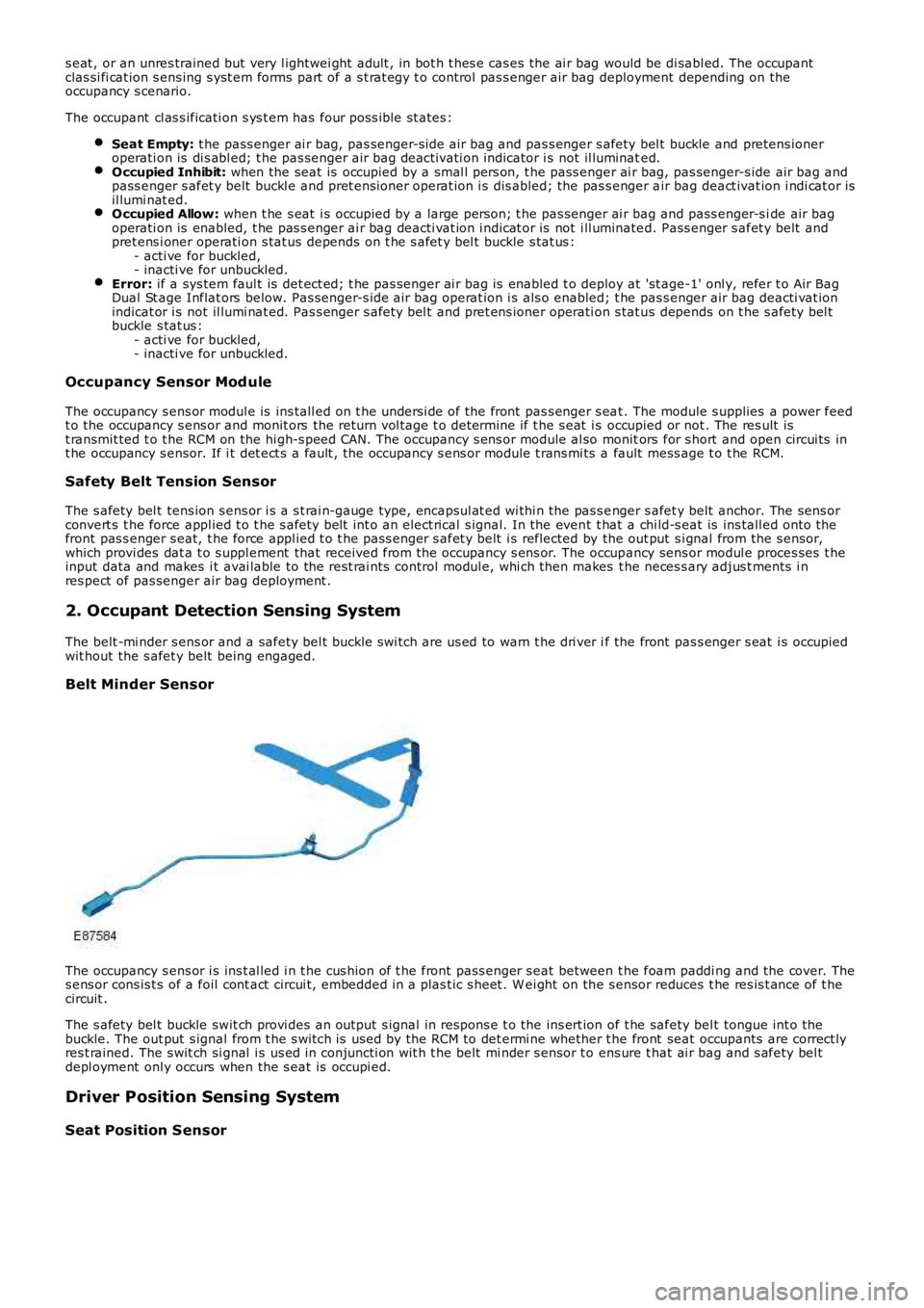
s eat , or an unres trained but very l ightwei ght adult , in bot h t hes e cas es the ai r bag would be di sabl ed. The occupantclas si fi cat ion s ens ing s yst em forms part of a s t rat egy t o control pas s enger air bag deployment depending on theoccupancy s cenario.
The occupant cl as s ificati on s ys t em has four pos s ible st ates :
Seat Empty: t he pass enger ai r bag, pas senger-s ide air bag and pas s enger s afety bel t buckle and pretens ioneroperati on is di s abl ed; t he pas senger air bag deact ivati on indicator i s not il luminated.Occupied Inhibit: when the seat is occupied by a smal l pers on, t he pass enger ai r bag, pas senger-s ide air bag andpass enger s afet y belt buckl e and pret ensi oner operat ion i s dis abled; the pas s enger air bag deact ivat ion i ndi cat or isil lumi nat ed.Occupied Allow: when t he s eat i s occupied by a large pers on; t he pas senger ai r bag and pass enger-s ide air bagoperati on is enabled, t he pas s enger ai r bag deacti vat ion i ndicat or is not i ll uminated. Pass enger s afet y belt andpret ens i oner operati on s tat us depends on t he s afet y bel t buckle s tat us :- acti ve for buckled,- inacti ve for unbuckled.Error: if a sys tem faul t is det ect ed; t he pas senger ai r bag is enabled t o deploy at 'st age-1' onl y, refer t o Air BagDual St age Inflat ors below. Pas senger-s ide air bag operat ion i s als o enabled; t he pas s enger air bag deacti vat ionindicat or i s not il lumi nat ed. Pas s enger s afety bel t and pret ens ioner operati on s tat us depends on t he s afety bel tbuckle s tat us :- acti ve for buckled,- inacti ve for unbuckled.
Occupancy Sensor Mod ule
The occupancy s ens or modul e is ins tall ed on t he undersi de of the front pas s enger s eat . The module s upplies a power feedt o the occupancy s ens or and monit ors the return vol tage t o det ermi ne if t he s eat i s occupied or not . The res ult ist ransmit ted t o t he RCM on the hi gh-s peed CAN. The occupancy s ens or module al so monitors for s hort and open circui ts int he occupancy s ensor. If i t det ect s a fault , the occupancy s ens or module t rans mi ts a fault mess age t o t he RCM.
Safety Belt Tension Sensor
The s afety bel t tens ion s ens or i s a s t rai n-gauge type, encapsul at ed wi thi n the pas s enger s afet y belt anchor. The sens orconvert s t he force appl ied t o t he s afety bel t int o an elect rical s ignal. In the event t hat a chi ld-s eat is ins tall ed onto thefront pas s enger s eat, t he force appl ied t o t he pass enger s afet y belt i s reflected by the out put s i gnal from the s ensor,which provi des dat a t o s uppl ement that received from the occupancy s ens or. The occupancy sens or modul e proces ses t heinput data and makes i t avai lable to the rest rai nts control modul e, whi ch then makes t he neces s ary adjus t ments i nres pect of pas senger air bag deployment .
2. Occupant Detection Sensing System
The belt -mi nder s ens or and a safety bel t buckle s wi tch are us ed to warn t he dri ver if the front pas s enger s eat i s occupiedwit hout the s afet y belt being engaged.
Belt Minder Sensor
The occupancy s ens or i s ins t al led i n t he cus hion of t he front pass enger s eat between t he foam paddi ng and the cover. Thes ens or cons is t s of a foil cont act circui t, embedded in a plas t ic s heet . W ei ght on the s ensor reduces t he res is t ance of t hecircuit .
The s afety bel t buckle swit ch provi des an output s ignal in respons e t o the ins ert ion of t he safety bel t tongue int o t hebuckle. The out put s ignal from t he s wit ch is used by the RCM to det ermi ne whether t he front seat occupants are correct lyres t rained. The s wit ch si gnal i s us ed in conjuncti on wit h t he belt mi nder s ensor t o ens ure t hat ai r bag and s afety bel tdepl oyment onl y occurs when the s eat is occupi ed.
Driver Position Sensing System
Seat Position Sensor
Page 2878 of 3229

Maintenance
158
L
One or both types of serv ice interval (distance
and time) may be displayed. For example, if an
engine oil service is du e based on mileage, and
a brake fluid change is due based on time, both
distance and time c ountdowns will display.
Service Portfolio
The Service Portfolio book includes a Service
Record section, which enables a record to be
kept of all the servicing and inspections that are
carried out on the vehicle. This section of the
book also has an area for brake fluid changes
to be recorded.
Ensure your service provider signs and stamps
the book after each se rvice and inspection.
Owner Maintenance
In addition to the routine maintenance, a
number of simple checks must be carried out
more frequently. Advice is given on the pages
that follow.
Daily checks
• Operation of lamps, horn, direction
indicators, wipers, washers and warning
indicators.
• Operation of seat belts and brakes.
• Look for fluid deposits underneath the
vehicle that might indicate a leak.
Weekly checks
• Engine oil level. See ENGINE OIL CHECK
(page 162).
• Engine coolant check. See ENGINE
COOLANT CHECK (page 163).
• Brake/clutch fluid level. See BRAKE AND
CLUTCH FLUID CHECK (page 165). •
Power steering fluid level. See POWER
STEERING FLUID CHECK (page 166).
• Screen washer fluid level. See WASHER
FLUID CHECK (page 167).
• Tyre pressure s and condition.
• Operate air conditioning.
Note: The engine oil leve l should be checked
more frequently if the vehicle is driven for
prolonged periods at high speeds.
Driving in arduous conditions
When a vehicle is operated in extremely
arduous conditions, more frequent attention
must be paid to servicing requirements.
For example, if your vehicle experiences deep
wading conditions, even daily servicing could
be necessary to ensure the continued safe and
reliable operation of the vehicle.
Arduous driving conditions include:
• Driving in dusty and/or sandy conditions.
• Driving on rough and/or muddy roads
and/or wading.
• Driving in extremely hot conditions.
• Towing a trailer or driving in mountainous
conditions.
Contact a Land Rover Dealer/Authorised
Repairer for advice.
Emission control
Your vehicle is fitted with various items of
emission and evaporative control equipment,
designed to meet sp ecific territorial
requirements. You should be aware that
unauthorised replacemen t, modification or
tampering with this equipment by an owner or
repair shop, may be unlawful and subject to
legal penalties.
CAUTION
Any significant or sudden drop in fluid
levels, or uneven tyre wear, should be
reported to a qualified technician without
delay.
Page 3012 of 3229
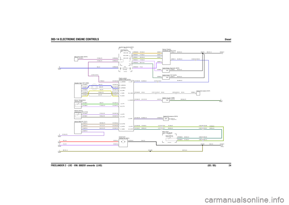
303-14 ELECTRONIC ENGINE CONTROLS
Diesel
FREELANDER 2 - LR2 - VIN: 000201 onwards (LHD) (03 / 05) 24
BU-BN,0.75BK,10.0
GY,0.5
BK-YE,4.0
BU-WH,0.5
RD,10.0VT,0.75VT-GY,0.75BK-YE,1.5
YE-VT,0.75BU-GY,0.75YE-BU,0.75WH-BN,0.75
YE-GN,0.5GN-BU,0.5
BU,4.0
GN-VT,0.5
VT-BN,0.75
GN,0.75VT-GY,0.75VT-WH,0.75WH,0.75BU,0.75YE-BU,0.75GY,0.75YE,0.75VT-BN,0.5
GY-VT,0.75GY,0.5BU-WH,0.5
VT-BN,0.75
YE-OG,0.5VT-WH,0.5VT,0.5VT-GN,0.5GN-OG,0.5
BK,10.0GN-BU,0.5YE-GN,0.5
GN-BU,0.5YE-GN,0.5
GN-BU,0.5YE-GN,0.5
BK-GY,0.5
BK-GN,0.75GY,0.5
BK-GY,1.5
BK-GY,0.5BK-GY,0.5BU-WH,0.5
FS4
5.0 Amps
C11P-7 C11N-7C11P-6 C11N-6
temperature (IAT) (T116)
Sensor-Inlet air-
module (ECM) (D131)
Engine control-
E
Sheet1Y
Sheet2L
Sheet1P
Sheet1
Sensor-MAF/IAT (T317)
Cooling Fan (D241)
Control Unit-
W
Sheet1
Actuator-Vane VGT (D363)Fuel rail (T125)
Sensor-Temperature-
C11N-4 C11P-4
C11P-17 C11N-17C11P-5 C11N-5
Stop lamp switch (S215)
Junction box-Central (P101)Module (CEM) (D316)
Central Electronics
C25B-20 C25A-20C12H-36 C12G-36
Driver side (M168)
Mirror-Door-
temperature (T119)
Sensor-Ambient air-
C25B-19 C25A-19
Switch-Oil pressure (S216)
fixings (E110)
Earth via-
C12H-31 C12G-31
TYPE 3
Instrument cluster (D107)
Switch-1st gear (S386)
C21D-6 C21C-6
Switch-Clutch-TOT (S472)
Z
Sheet4
Accelerator pedal (T113)
Sensor-Position-Switch-Brake diagnostic (S473)
C12G-30 C12H-30
C1MC24A-2C2E904-2C2CB08-1C1ET37-1C2E901-2C2E901-6C2E901-3C2E901-1
C1E740B-2
C1E104F-G2
I_A_IATSC1E104F-A1I_F_AMS2C1E104F-F2G_R_IATSC1EC01A-1C1EC01A-4C1E104G-J3G_R_IATS3C1E104G-H3 I_A_IATS3
C1E807D-5C1E807D-2C1E807D-3C1E740B-1C1E807D-4
C1EC01A-2
S1D129B
C1E104G-H4
I_S_OPSC1E104H-D2
I_A_IATSC1E104H-E1
G_R_IATS
C1E104F-D1 I_A_FTSC1E104H-G3I_S_BRKMNC1E104F-E1 G_R_FTSC1E104F-E2 I_F_BPAC1E104F-J3 O_T_BPAPOSC1E104F-H3
O_T_BPANEGC1E104F-J1 VV_5VV2C1E104F-C3G_R_BPA
C1E728B-2C1E728B-1C1E432B-5C1E432B-1C1E432B-4C1E432B-2C1E432B-3
C1E104H-F3
L_S_GEAR1C1E104H-B1
B_D_ISOKC1E104H-H4
I_T_APP
C1BP02B-54C1BP02A-37C1BP02A-65
C2CA29-2
C1BP02B-29
ACCL SIG
C1BP02B-33C1BP02B-55
ACCL SUPACCL GND
C1BP02B-11C1BP02B-12C1BP02B-47
C5PM26B-5C5PM26B-6
S1D129
G1D129-1
C1ET37-2
GNDC2E904-3
GND
C2DB04-7
S3D135
C2E901-4C2CB08-2
GNDC2E901-5
G3D135-1