2006 LAND ROVER FRELANDER 2 oil type
[x] Cancel search: oil typePage 800 of 3229
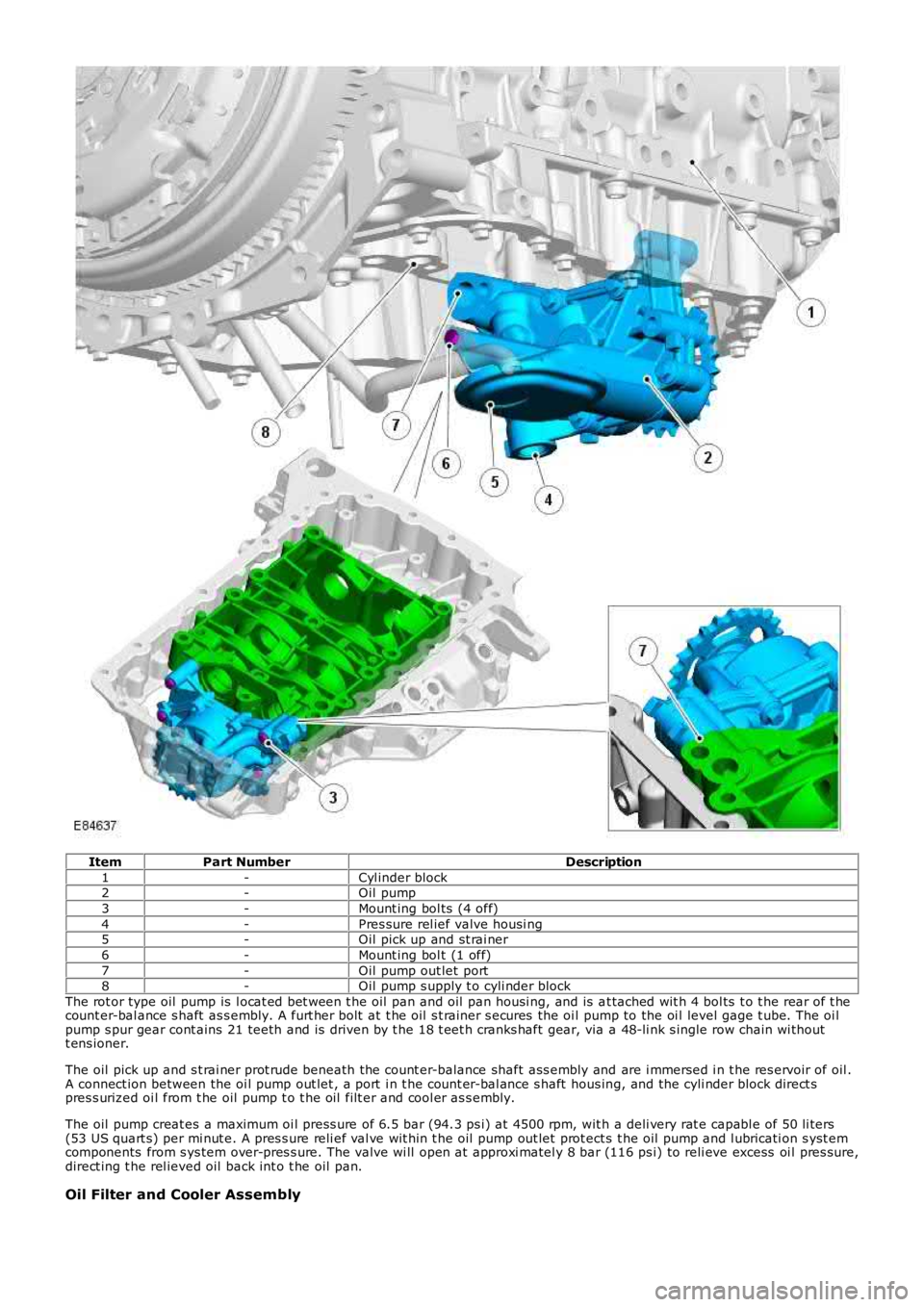
ItemPart NumberDescription
1-Cyl inder block2-Oil pump
3-Mount ing bol ts (4 off)
4-Pres sure rel ief valve housi ng5-Oil pick up and st rai ner
6-Mount ing bol t (1 off)
7-Oil pump out let port8-Oil pump s upply t o cyli nder block
The rot or type oil pump is l ocat ed bet ween t he oil pan and oil pan housi ng, and is at tached wit h 4 bol ts t o t he rear of t hecount er-bal ance s haft as s embly. A furt her bolt at t he oil s t rainer s ecures the oi l pump to the oi l level gage t ube. The oi lpump s pur gear cont ains 21 teeth and is driven by t he 18 t eet h cranks haft gear, via a 48-li nk s ingle row chain wi thoutt ens ioner.
The oil pick up and s t rai ner prot rude beneath the count er-balance shaft ass embly and are i mmersed i n t he res ervoir of oil .A connect ion between the oi l pump out let , a port i n t he count er-bal ance s haft hous ing, and the cyli nder block direct spres s urized oi l from t he oil pump t o t he oil filt er and cool er as s embly.
The oil pump creat es a maximum oi l press ure of 6.5 bar (94.3 ps i) at 4500 rpm, wit h a deli very rat e capabl e of 50 li ters(53 US quart s) per mi nut e. A pres s ure reli ef val ve wit hin t he oil pump out let prot ect s t he oil pump and l ubricati on s yst emcomponents from s ys tem over-pres s ure. The valve wi ll open at approxi matel y 8 bar (116 ps i) to reli eve excess oi l pres sure,direct ing t he rel ieved oil back int o t he oil pan.
Oil Filter and Cooler Assembly
Page 801 of 3229
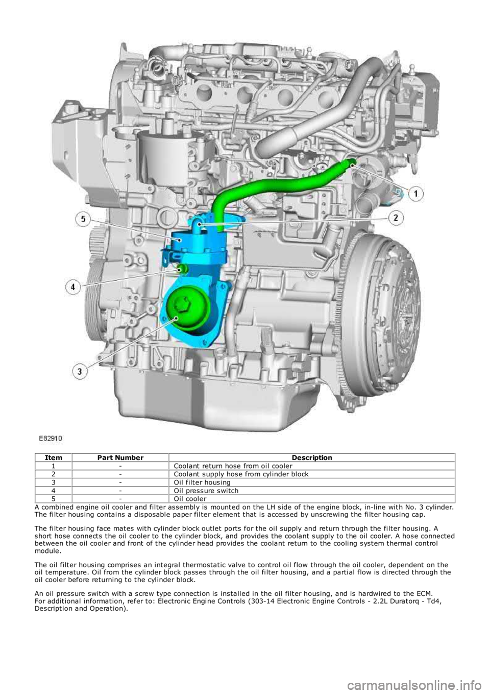
ItemPart NumberDescription
1-Cool ant return hose from oi l cooler2-Cool ant s upply hos e from cyl inder bl ock
3-Oil filt er hous i ng
4-Oil pres s ure s wi tch5-Oil cool er
A combined engine oi l cooler and fil ter as sembl y is mount ed on t he LH s ide of t he engine block, in-line wit h No. 3 cylinder.The fi lt er hous ing contai ns a dis pos abl e paper fil ter element t hat i s acces s ed by unscrewi ng t he fi lt er hous ing cap.
The fi lt er hous ing face mat es wit h cyl inder block out let ports for the oi l supply and return t hrough the fi lt er hous ing. As hort hose connect s t he oil cool er to the cyli nder block, and provides the coolant suppl y t o t he oil cool er. A hos e connectedbetween t he oil cooler and front of t he cylinder head provides t he coolant return to the cooli ng s ys t em t hermal cont rolmodule.
The oil filt er hous i ng compris es an i nt egral t hermos tat ic valve t o cont rol oi l flow through the oi l cooler, dependent on t heoil t emperature. Oil from the cyli nder block pass es t hrough t he oil fi lt er hous ing, and a parti al flow is di rected t hrough t heoil cool er before returning t o t he cyl inder bl ock.
An oil press ure swit ch wit h a s crew type connecti on is ins tall ed in the oi l fi lt er hous ing, and is hardwired to the ECM.For addit ional informat ion, refer t o: Electroni c Engi ne Controls (303-14 Electronic Engine Controls - 2.2L Durat orq - Td4,Des cript ion and Operat ion).
Page 911 of 3229
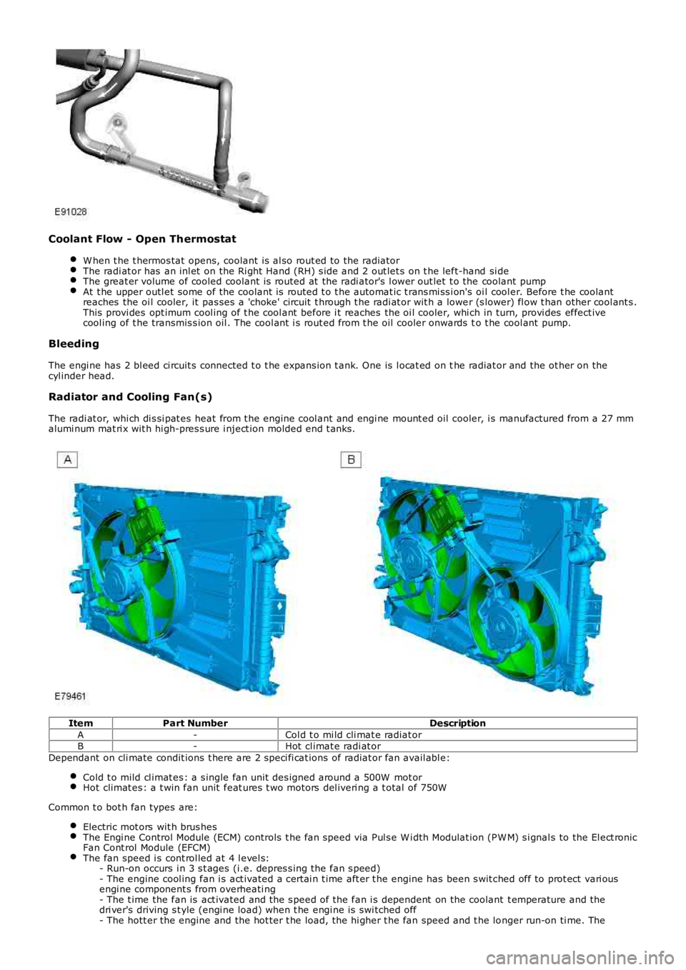
Coolant Flow - Open Thermostat
W hen t he t hermos tat opens, coolant is al so rout ed to the radiatorThe radi at or has an inl et on the Ri ght Hand (RH) s ide and 2 out let s on t he left-hand si deThe great er volume of cooled coolant is routed at the radi ator's l ower out let t o the coolant pumpAt t he upper outl et some of the coolant is routed t o t he automat ic t rans mi ss i on's oil cool er. Before t he coolantreaches the oi l cooler, it pas ses a 'choke' circuit t hrough t he radi at or wit h a lower (s lower) fl ow t han other cool ant s .This provi des opt imum cool ing of t he cool ant before i t reaches the oi l cooler, whi ch in turn, provi des effect ivecool ing of t he transmis s ion oil . The cool ant i s rout ed from t he oil cooler onwards to t he cool ant pump.
Bleeding
The engi ne has 2 bl eed ci rcuit s connected t o t he expans ion t ank. One is l ocat ed on the radiat or and the ot her on thecyl inder head.
Radiator and Cooling Fan(s)
The radi at or, whi ch di s si pat es heat from t he engine cool ant and engi ne mount ed oil cooler, i s manufactured from a 27 mmalumi num mat ri x wit h hi gh-pres s ure i nject ion molded end t anks .
ItemPart NumberDescription
A-Col d t o mi ld cli mat e radiat orB-Hot cl imat e radi at or
Dependant on cli mate condit ions t here are 2 s peci fi cat ions of radiat or fan avail abl e:
Cold t o mild cl imat es : a s ingle fan unit des igned around a 500W mot orHot climat es : a t win fan unit feat ures t wo motors del iveri ng a t otal of 750W
Common t o bot h fan types are:
Electric mot ors wit h brus hesThe Engi ne Control Module (ECM) controls t he fan speed via Pul s e W i dth Modulat ion (PW M) s i gnal s to the El ect ronicFan Cont rol Module (EFCM)The fan speed i s cont rol led at 4 l evel s:- Run-on occurs i n 3 s t ages (i.e. depres s ing the fan s peed)- The engine cool ing fan i s act ivated a cert ai n t ime aft er t he engine has been s wit ched off to prot ect vari ousengi ne component s from overheati ng- The t ime the fan is act ivated and the s peed of the fan i s dependent on the coolant t emperature and thedri ver's driving s t yle (engi ne load) when t he engi ne is swi tched off- The hott er the engine and the hot ter t he load, the hi gher t he fan speed and t he longer run-on ti me. The
Page 942 of 3229
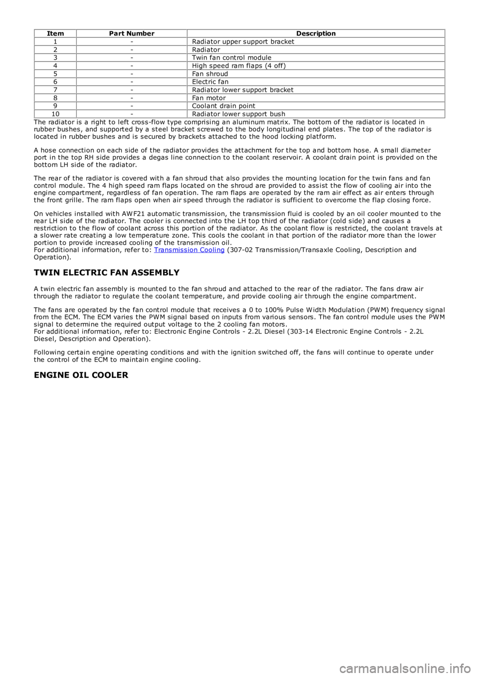
ItemPart NumberDescription
1-Radi ator upper s upport bracket
2-Radi ator3-Twin fan cont rol module
4-High s peed ram fl aps (4 off)
5-Fan shroud6-Elect ric fan
7-Radi ator lower s upport bracket
8-Fan motor9-Cool ant drain point
10-Radi ator lower s upport bus h
The radi at or is a ri ght t o l eft cros s -flow type compri si ng an alumi num mat ri x. The bot tom of the radiat or i s l ocated inrubber bus hes , and support ed by a s t eel bracket s crewed to the body l ongi tudinal end plates . The t op of the radiator i slocated i n rubber bushes and i s s ecured by bracket s at tached to the hood l ocking pl at form.
A hos e connecti on on each s ide of t he radiat or provi des the at t achment for t he t op and bot t om hos e. A s mall diamet erport i n t he top RH s ide provi des a degas l ine connect ion t o t he cool ant reservoi r. A coolant drai n point i s provided on t hebott om LH si de of the radiat or.
The rear of t he radiat or is covered wit h a fan s hroud t hat als o provides t he mounti ng locati on for t he t win fans and fancont rol module. The 4 hi gh s peed ram flaps l ocat ed on t he s hroud are provi ded to assi st t he flow of cooling ai r int o t heengi ne compart ment , regardl ess of fan operat ion. The ram fl aps are operat ed by the ram air effect as ai r ent ers throught he front gril le. The ram fl aps open when air s peed through t he radi at or is suffi ci ent t o overcome t he flap clos ing force.
On vehicles i nst all ed wit h AW F21 aut omati c transmis si on, the t rans mis s ion flui d is cooled by an oil cool er mount ed t o t herear LH s i de of the radi ator. The cooler i s connected i nto t he LH t op t hird of the radiator (col d s ide) and caus es ares t ri ct ion t o t he flow of coolant across this porti on of the radiat or. As t he cool ant flow is rest ri cted, the coolant t ravels ata s lower rate creat ing a low temperat ure zone. Thi s cool s t he cool ant i n t hat porti on of the radiator more t han the l owerport ion t o provi de increas ed cooli ng of the trans mi s si on oil .For addit ional informat ion, refer t o: Trans mis s ion Cooli ng (307-02 Trans mis s ion/Trans axle Cooli ng, Des cri pti on andOperat ion).
TWIN ELECTRIC FAN ASSEMBLY
A t win electric fan ass embl y is mount ed t o the fan s hroud and at tached to the rear of the radi ator. The fans draw airt hrough the radiator t o regul at e t he cool ant temperat ure, and provide cooli ng air t hrough the engi ne compartment .
The fans are operated by the fan cont rol module that receives a 0 to 100% Puls e W idth Modulati on (PW M) frequency s ignalfrom the ECM. The ECM varies t he PW M si gnal bas ed on inputs from vari ous sens ors . The fan cont rol module us es t he PW Ms ignal to det ermi ne the required out put vol tage t o t he 2 cooling fan mot ors .For addit ional informat ion, refer t o: Electroni c Engi ne Controls - 2.2L Dies el (303-14 El ect ronic Engine Cont rols - 2.2LDies el, Des cript ion and Operat ion).
Followi ng certai n engine operat ing condi ti ons and wit h t he ignit ion s wi tched off, the fans wil l cont inue t o operate undert he cont rol of the ECM to maint ai n engine cooling.
ENGINE OIL COOLER
Page 997 of 3229
(23,206 psi ).
The fuel s yst em HP pump compri ses t he fol lowi ng components :
3 HP pumpi ng element sInt egral li ft pumpVolume Cont rol Valve (VCV).
The HP pump and integral l ift pump mus t not be s eparat ed. The HP pump i s not ti med to t he engi ne.
A controlled amount of fuel i s all owed to leak-off t hrough t he HP pump, and ret urned t hrough a l eak-off pipe t o t he fuelfi lt er. The l eak-off fuel provides cooling and lubri cat ion for the HP pump int ernal components .
Lift Pump
A fuel l ift pump i s mounted t o t he rear of t he fuel pump, and forms an int egral ass embly wit h t he HP pump. The fuel li ftpump i s a gear type pump and connect ed to the fuel fi lt er s upply l ine. The li ft pump creat es a vacuum (negati ve pres s ure)in the s upply l ine t o t he fuel t ank, and draws the fuel from t he tank. The fuel passes t hrough the fuel fi lt er and i s t hendelivered at lift pump pres s ure to the HP pump inl et port.
The li ft pump normal operati ng, negati ve pres sure values are shown for the foll owing engine condi ti ons:
Engine ConditionLift Pump Negative PressureCranking-133 ± 7 mbar (-10 ± 0.5 cmHg)
Full load-267 ± 133 mbar (-20 ± 10 cmHg)
Volume Control Valve (VCV)
The VCV i s mounted on the HP pump, and l ocat ed in the feed port between t he HP pump elements and the fuel l ift pump.The VCV i s a vari abl e pos it ion s olenoid-operat ed valve t hat i s cont rol led by t he ECM wit h a 12V Puls e W idt h Modulat ed(PW M) s ignal. The VCV controls t he quant it y of fuel deli vered by the lift pump t o t he HP pump el ements .
W hen t he HP fuel pump rot ates , pres sure is created when t he VCV i s open and the fuel rail mount ed PCV is cl osed. TheVCV and PCV are vari abl e posi ti on valves, and us ed by t he ECM t o cont rol fuel deli very and fuel s ys tem pres sure.
Duri ng the fuel heat ing period when t he s uppl y fuel t emperature is les s than 40°C (104°F), t he ECM will fully open theVCV. Fuel volume and press ure is t hen cont rol led di rectl y by the PCV under t he cont rol of the ECM.
The VCV i s normal ly open when t he s ol enoi d i s not energi zed by the ECM. The resi s tance val ue of the VCV s ol enoi d coil is2.8 ohms at 20°C (68°F).For addit ional informat ion, refer t o: Electroni c Engi ne Controls - 2.2L Dies el (303-14 El ect ronic Engine Cont rols - 2.2LDies el, Des cript ion and Operat ion).
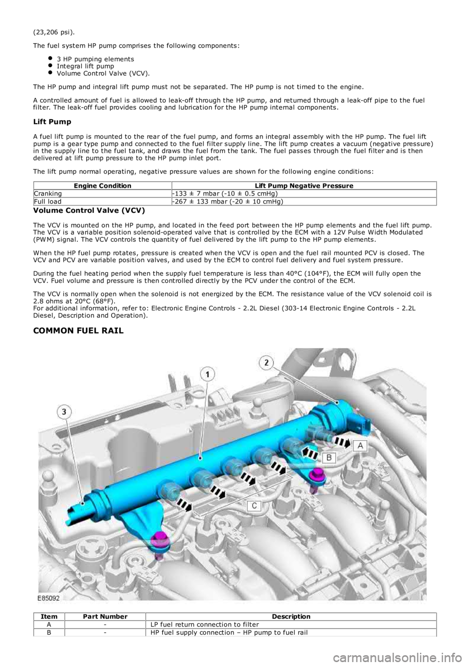
COMMON FUEL RAIL
ItemPart NumberDescription
A-LP fuel return connecti on t o fi lt er
B-HP fuel s upply connect ion – HP pump t o fuel rail
Page 1024 of 3229
Publi s hed: 11-May-2011
Fuel Charging and Controls - Turbocharger - TD4 2.2L Diesel -
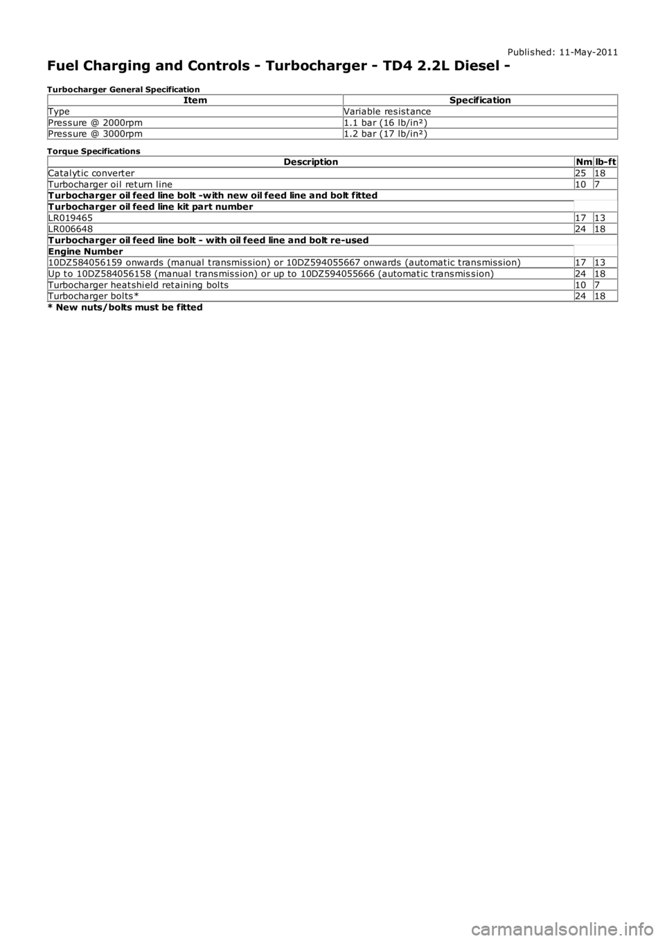
Turbocharger General SpecificationItemSpecification
TypeVariable res is t ance
Pres s ure @ 2000rpm1.1 bar (16 lb/in²)Pres s ure @ 3000rpm1.2 bar (17 lb/in²)
Torque SpecificationsDescriptionNmlb-ft
Catal yt ic convert er2518
Turbocharger oi l ret urn l ine107T urbocharger oil feed line bolt -w ith new oil feed line and bolt fitted
T urbocharger oil feed line kit part number
LR0194651713LR0066482418
T urbocharger oil feed line bolt - with oil feed line and bolt re-used
Engine Number10DZ584056159 onwards (manual t ransmis s ion) or 10DZ594055667 onwards (automat ic t rans mis s ion)1713
Up t o 10DZ584056158 (manual t rans mis s ion) or up to 10DZ594055666 (automat ic t rans miss ion)2418
Turbocharger heat shi el d ret aini ng bol ts107Turbocharger bol ts *2418
* New nuts/bolts must be fitted
Page 1025 of 3229
Publi s hed: 11-May-2011
Fuel Charging and Controls - Turbocharger - TD4 2.2L Diesel - Turbocharger
Des cript ion and Operat ion
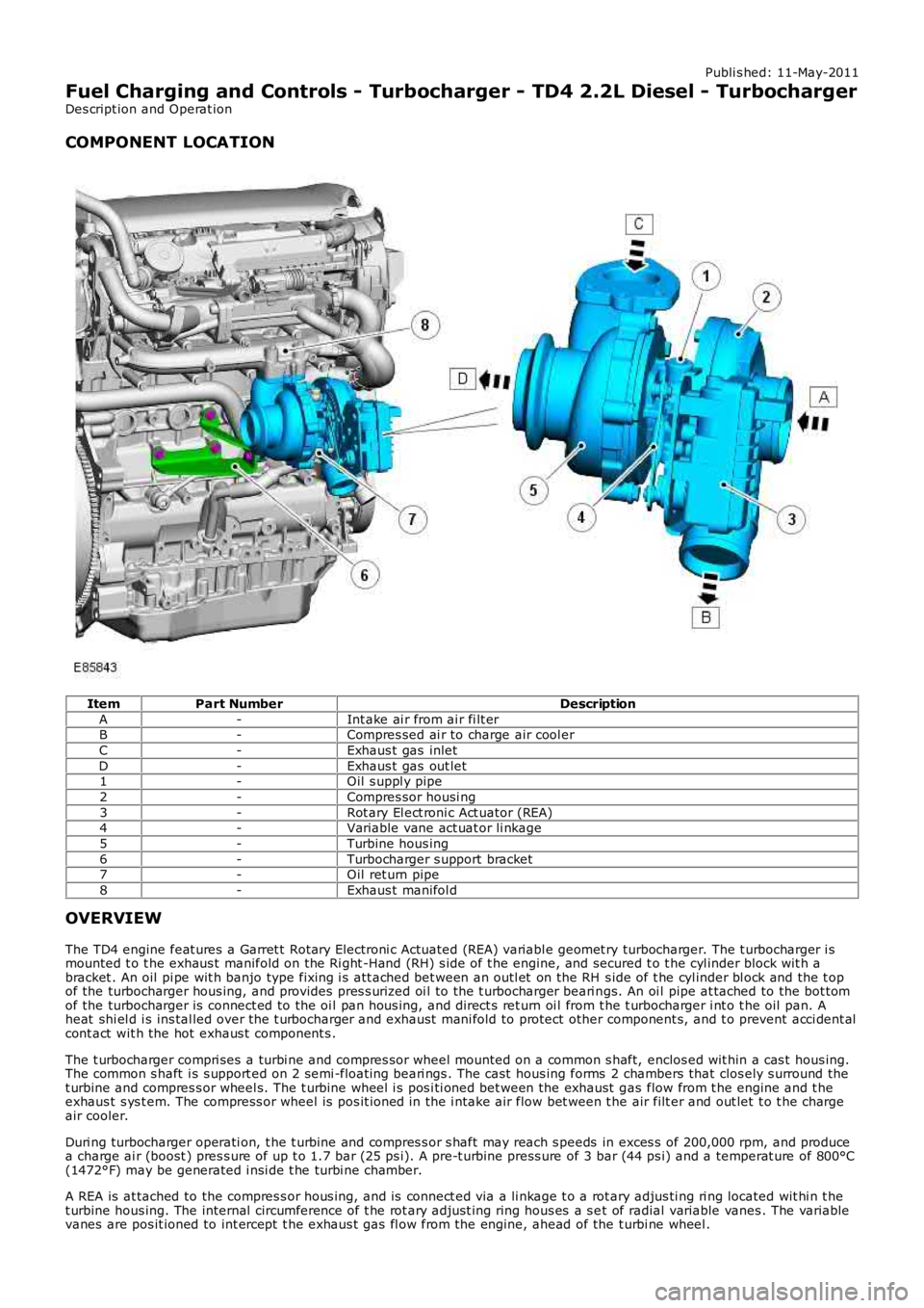
COMPONENT LOCATION
ItemPart NumberDescription
A-Int ake ai r from ai r fi lt erB-Compres sed ai r to charge air cool er
C-Exhaus t gas inlet
D-Exhaus t gas out let1-Oil s uppl y pipe
2-Compres sor housi ng
3-Rot ary El ect roni c Act uator (REA)4-Variable vane act uat or li nkage
5-Turbine hous ing
6-Turbocharger s upport bracket7-Oil ret urn pipe
8-Exhaus t manifol d
OVERVIEW
The TD4 engine feat ures a Garret t Rotary Electroni c Actuated (REA) variabl e geomet ry turbocharger. The t urbocharger i smounted t o t he exhaus t manifold on the Ri ght -Hand (RH) s ide of t he engine, and secured t o t he cyl inder block wit h abracket . An oil pi pe wit h banjo type fixing i s att ached bet ween an outl et on the RH s ide of t he cyl inder bl ock and the t opof the turbocharger hous ing, and provides pres s uri zed oi l to the t urbocharger beari ngs. An oi l pipe at tached to the bot tomof the turbocharger is connect ed to the oi l pan hous ing, and direct s ret urn oi l from t he t urbocharger i nt o t he oil pan. Aheat shi el d i s ins tal led over the t urbocharger and exhaust mani fold to protect other component s, and t o prevent acci dent alcont act wit h the hot exhaus t component s .
The t urbocharger compri ses a turbi ne and compres sor wheel mounted on a common s haft, enclos ed wit hin a cas t hous ing.The common s haft i s s upport ed on 2 semi -float ing beari ngs . The cast hous ing forms 2 chambers that clos ely s urround thet urbine and compres s or wheel s. The t urbine wheel i s pos i ti oned bet ween the exhaust gas flow from t he engine and t heexhaus t s ys t em. The compress or wheel is pos it ioned in the i ntake air flow bet ween t he air filt er and out let t o t he chargeair cooler.
Duri ng turbocharger operati on, t he t urbine and compres s or s haft may reach s peeds in exces s of 200,000 rpm, and producea charge ai r (boost ) pres s ure of up t o 1.7 bar (25 ps i). A pre-t urbine press ure of 3 bar (44 ps i) and a temperat ure of 800°C(1472°F) may be generated i nsi de t he turbi ne chamber.
A REA is at tached to the compres s or hous ing, and is connect ed via a li nkage t o a rotary adjus ti ng ri ng located wit hi n t het urbine hous ing. The internal circumference of t he rot ary adjus t ing ring hous es a s et of radial variable vanes . The variablevanes are pos it ioned to int ercept t he exhaus t gas fl ow from the engine, ahead of the t urbi ne wheel .
Page 1111 of 3229
Publi s hed: 11-May-2011
Engine Ignition -
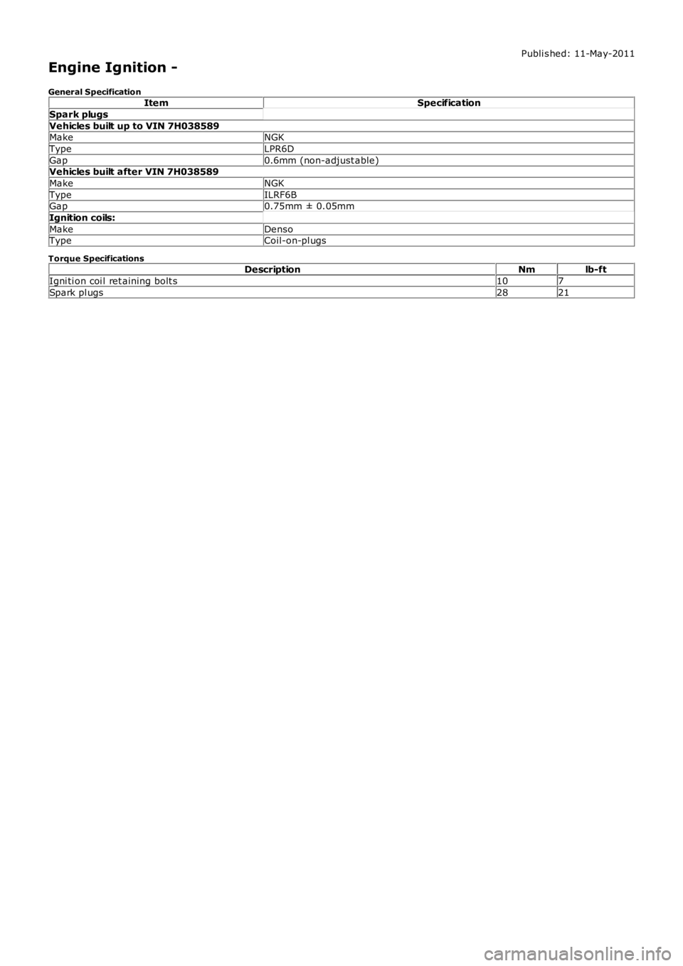
General SpecificationItemSpecification
Spark plugs
Vehicles built up to VIN 7H038589MakeNGK
TypeLPR6D
Gap0.6mm (non-adjust able)Vehicles built after VIN 7H038589
MakeNGK
TypeILRF6BGap0.75mm ± 0.05mm
Ignition coils:
MakeDensoTypeCoil-on-pl ugs
Torque SpecificationsDescriptionNmlb-ft
Igni ti on coi l ret aining bolt s107
Spark pl ugs2821