2006 DODGE RAM SRT-10 lock
[x] Cancel search: lockPage 889 of 5267
8.INTAKE SYSTEM
Check for inlet restriction, inspect air filter for excessive dirt/debris. Verify air intake lines are not kinked or restricted.
Check for air system leaks. Perform “*INTAKE AIR SYSTEM PRESSURE TEST - DIESEL”.
Inspect Turbocharger for wheel clearance and proper wastegate operation.
Check for exhaust restriction. Verify proper exhaust brake operation. Check for kinked or blocked exhaust pipes.
Is vehicle repaired?
Ye s>>
Repair complete.
Perform POWERTRAIN VERIFICATION TEST VER - 1 (DIESEL). (Refer to 8 - ELECTRICAL/ELEC-
TRONIC CONTROL MODULES/ENGINE CONTROL MODULE - DIAGNOSIS AND TESTING)
No>>
Go To 9
9.OTHER VEHICLE SYSTEMS
Verify proper operation of the Transmission Clutch.
Verify proper operation of the Transmission.
Verify proper operation of the Vehicle brakes (check for dragging).
Verify proper operation of the Cooling fan operation cycle time.
Verify proper operation of the Engine driven accessories.
Verify proper operation of the Accelerator pedal (restricted or out of calibration).
Verify no excess Electrical Noise.
Verify no Moisture in harness connector or corroded terminals.
Is vehicle repaired?
Ye s>>
Repair complete.
Perform POWERTRAIN VERIFICATION TEST VER - 1 (DIESEL). (Refer to 8 - ELECTRICAL/ELEC-
TRONIC CONTROL MODULES/ENGINE CONTROL MODULE - DIAGNOSIS AND TESTING)
No>>
Go To 7
10.BASE ENGINE
Inspect speed indicator ring for damaged/missing teeth.
Check for internal engine damage.
Repair Complete.
Ye s>>
Repair complete.
Perform POWERTRAIN VERIFICATION TEST VER - 1 (DIESEL). (Refer to 8 - ELECTRICAL/ELEC-
TRONIC CONTROL MODULES/ENGINE CONTROL MODULE - DIAGNOSIS AND TESTING)
Page 897 of 5267
*INTAKE AIR SYSTEM PRESSURE TEST
Diagnostic Test
1.CHARGE AIR COOLER PRESSURE TEST
Loosen air inlet tube clamp at the turbocharger.
Remove the air filter housing and the inlet tube from the vehicle as an assembly.
Install the CAC Pressure Tester #9022 into the inner diameter of the turbocharger, securing it in place with the
supplied three-fingered band clamp, tighten tool clamp to 8n.m (72 in lbs).
NOTE: NEVER ATTEMPT TO START OR RUN THE VEHICLE AT ANY TIME DURING THIS TEST,ENGINE DAM-
AGE MAY OCCUR.
Fasten the safety chain around a solid surface behind the turbocharger. Warning: Never run CAC Pressure test
without the safety chain securely fastened.
Before attaching shop air to the pressure regulator verify that the regulator is at its lowest pressure setting (0 psi).
Attach an air supply to the regulator and slowly increase the pressure until the pressure gauge reads 20 psi.
WARNING: WARNING: Never apply more than 20 PSI.
Using a solution of soap and water spray the Turbocharger, Turbocharger wastegate, Charge Air Cooler Heat
Exchange and CAC Hoses while watching for leaks.
Before any attempt to repair the CAC system is made, its necessary to completely discharge the system. This can
be accomplished by turning the regulator knob counter-clockwise.
Allow for adequate time to pass before removing the CAC Pressure tester from the turbo charger inlet.
Position the Air Filter Housing over thethreemountingstudslocatedonthe inside front fender well and press down
firmly to lock housing into place.
Install Air Inlet Tube over the Turbocharger inlet and torque the band clampto35in.lbs.
View Repair
Repair
Te s t c o m p l e t e .
Perform POWERTRAIN VERIFICATION TEST VER - 1 (DIESEL). (Refer to 8 - ELECTRICAL/ELEC-
TRONIC CONTROL MODULES/ENGINE CONTROL MODULE - DIAGNOSIS AND TESTING)
Page 900 of 5267
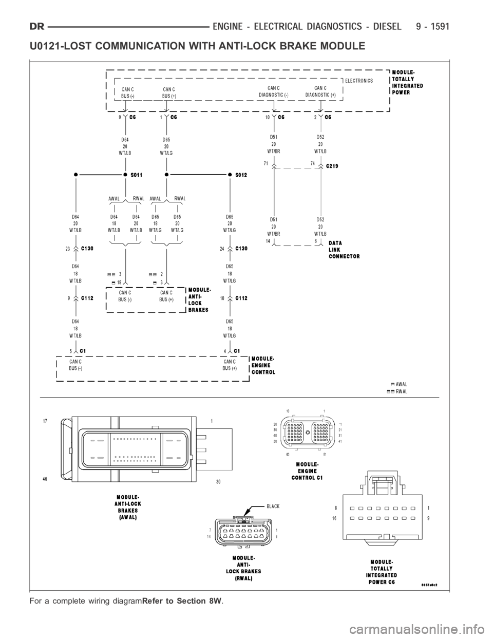
U0121-LOST COMMUNICATION WITH ANTI-LOCK BRAKE MODULE
For a complete wiring diagramRefer to Section 8W.
Page 912 of 5267

P0355-IGNITION COIL #5 PRIMARY
CIRCUIT................................. 1948
P0420-1/1 CATALYTIC CONVERTER
EFFICIENCY............................. 1952
P0432-2/1 CATALYTIC CONVERTER
EFFICIENCY............................. 1955
P0441-EVAP PURGE FLOW MONITOR . . . . . 1958
P0442-EVAP LEAK MONITOR MEDIUM
(0.040) LEAK DETECTED.................. 1962
P0443-EVAP PURGE SOLENOID CIRCUIT . . 1968
P0455-EVAP LEAK MONITOR LARGE LEAK
DETECTED............................... 1972
P0460-FUEL LEVEL SENDING UNIT NO
CHANGE OVER MILES.................... 1978
P0462-FUEL LEVEL SENDING UNIT VOLTS
TOO LOW................................ 1979
P0463-FUEL LEVEL SENSOR 1 CIRCUIT
HIGH.................................... 1982
P0500-NO VEHICLE SPEED SIGNAL ....... 1986
P0505-IDLE AIR CONTROL MOTOR
CIRCUITS................................ 1989
P0513-INVALID SKREEM KEY ............. 1994
P0522-OIL PRESSURE CIRCUIT LOW ...... 1996
P0523-OIL PRESSURE CIRCUIT HIGH ..... 2000
P0601-PCM INTERNAL CONTROLLER
FAILURE................................. 2003
P0622-GENERATOR FIELD NOT
SWITCHING PROPERLY.................. 2004
P0645-A/C CLUTCH RELAY CIRCUIT . . ..... 2008
P0801-REVERSE GEAR LOCKOUT CIRCUIT
OPEN OR SHORTED...................... 2012
P1195-O2 SENSOR 1/1 SLOW DURING
CATALYST MONITOR..................... 2016
P1196-O2 SENSOR 2/1 SLOW DURING
CATALYST MONITOR..................... 2019
P126B-ASD CONTROL CIRCUIT 2 LOW .... 2022
P126C-ASD CONTROL CIRCUIT 2 HIGH .... 2026
P126D-ASD CONTROL CIRCUIT 2 OPEN . . . 2030
P126E-ASD CONTROL CIRCUIT
OVERCURRENT.......................... 2034
P1272-A/C CLUTCH CONTROL CIRCUIT 2
LOW..................................... 2038
P1273-A/C CLUTCH CONTROL CIRCUIT 2
HIGH.................................... 2041
P1274-A/C CLUTCH CONTROL CIRCUIT 2
OPEN.................................... 2045
P1275-A/C CLUTCH CONTROL CIRCUIT 2
OVERCURRENT.......................... 2049
P1277-STARTER CONTROL CIRCUIT 2 LOW
(TIPM)................................... 2052
P1278-STARTER CONTROL CIRCUIT 2
HIGH (TIPM).............................. 2055
P1279-STARTER CONTROL CIRCUIT 2
OPEN (TIPM)............................. 2058
P127A-STARTER CONTROL CIRCUIT 2
OVERCURRENT.......................... 2061
P127C-FUEL PUMP CONTROL CIRCUIT 2
LOW..................................... 2064P127D-FUEL PUMP CONTROL CIRCUIT 2
HIGH.................................... 2067
P127E-FUEL PUMP CONTROL CIRCUIT 2
OPEN (TIPM)............................. 2071
P0127F-FUEL PUMP CONTROL CIRCUIT 2
OVERCURRENT (TIPM)................... 2075
P1281-ENGINE IS COLD TOO LONG ....... 2078
P1282-FUEL PUMP/SYSTEM RELAY
CONTROL CIRCUIT....................... 2079
P1294-TARGET IDLE NOT REACHED ...... 2082
P1296-NO 5-VOLTS TO MAP SENSOR ..... 2085
P1297-NO CHANGE IN MAP FROM START
TO RUN.................................. 2089
P1388-AUTO SHUTDOWN RELAY CONTROL
CIRCUIT................................. 2094
P1389-NO ASD RELAY OUTPUT VOLTAGE
AT P C M.................................. 2097
P1391-INTERMITTENT LOSS OF CMP OR
CKP
..................................... 2100
P1398-MIS-FIRE ADAPTIVE NUMERATOR
AT L I M I T................................. 2104
P1486-EVAP LEAK MONITOR PINCHED
HOSE FOUND............................ 2106
P1492-AMBIENT/BATTERY TEMPERATURE
SENSOR VOLTAGE TOO HIGH............. 2110
P1493-AMBIENT/BATTERY TEMPERATURE
SENSOR VOLTAGE TOO LOW............. 2114
P1494-LEAK DETECTION PUMP SWITCH
OR MECHANICAL FAULT.................. 2117
P1495-LEAK DETECTION PUMP SOLENOID
CIRCUIT................................. 2121
P1499-HYDRAULIC FAN SOLENOID
CIRCUIT................................. 2126
P1594-CHARGING SYSTEM VOLTAGE TOO
HIGH.................................... 2130
P1598-A/C PRESSURE SENSOR VOLTAGE
TOO HIGH............................... 2133
P1599-A/C PRESSURE SENSOR VOLTAGE
TOO LOW................................ 2137
P1682-CHARGING SYSTEM VOLTAGE TOO
LOW..................................... 2141
P1687-NO CLUSTER BUS MESSAGE ...... 2146
P1695-BUS MESSAGE FROM BODY
CONTROL MODULE...................... 2148
P1696-PCM FAILURE EEPROM WRITE
DENIED.................................. 2151
*BRAKE SWITCH SENSE STATUS DOES
NOT CHANGE ON THE SCAN TOOL....... 2153
*CANNOT SHIFT INTO REVERSE .......... 2157
*CHECKING A/C SYSTEM OPERATION
WITH NO DTCS.......................... 2159
*CHECKING CHARGING SYSTEM
OPERATION WITH NO DTCS.............. 2163
*CHECKING RADIATOR FAN OPERATION . . 2167
*CHECKING THE PCM POWER AND
GROUNDS............................... 2169
B2277–CAN GATEWAY INTERNAL
(GATEWAY).............................. 2172
U0001–CAN C BUS CIRCUIT (GATEWAY) . . . 2172
Page 913 of 5267
U0002–CAN C BUS PERFORMANCE
(GATEWAY).............................. 2172
U0100–LOST COMMUNICATION WITH
ECM/PCM (GATEWAY).................... 2172
U0121–LOST COMMUNICATION WITH
ANTI-LOCK BRAKE MODULE (GATEWAY). . 2172
U0155–LOST COMMUNICATION WITH
CLUSTER/CCN (GATEWAY)............... 2173U0168–LOST COMMUNICATION WITH
VEHICLE SECURITY CONTROL MODULE -
SKREEM/WCM (GATEWAY)................ 2173
STANDARD PROCEDURE
POWERTRAIN VERIFICATION TEST ....... 2174
Page 1273 of 5267
3.VISUAL AND PHYSICAL INSPECTION
Perform a visual and physical inspection of the entire Evaporative Emission system.
Check for the follow conditions:
- Holes or cracks
- Loose seal points
- Evidence of damaged components
- Incorrect routing of hoses and tubes
- Fuel Cap gasket seal
Were any of the above conditions found?
Ye s>>
Repair as necessary.
Perform the POWERTRAIN VERIFICATION TEST. (Refer to 9 - ENGINE - STANDARD PROCEDURE)
No>>
Go To 4
4.VERIFY EVAPORATIVE EMISSION LEAK
To continue testing you will need Miller Tool #8404A Evaporative EmissionLeak Detector (EELD).
WARNING: Keep lit cigarettes, sparks, flames, and other ignition sourcesaway from the test area to prevent
the ignition of explosive gases. Keep the test area well ventilated.
NOTE: The fuel tank should have between 20% and 80% of fuel tank capacity to properly test the Evap
system.
Connect the red power lead of the EELD to the battery positive terminal and the black ground lead to battery neg-
ative terminal.
Block the vent hose of the canister if using the service port.
Connect shop air to the EELD.
Set the smoke/air control switch to AIR.
Insert the tester’s AIR supply tip (clear hose) into the appropriate calibration orifice on the tester’s control panel
(based on DTC leak size).
Press the remote smoke/air start button.
Position the red flag on the air flow meter so it is aligned with the indicatorball.
When the calibration is complete, release the remote button. The EELD flowmeter is now calibrated in liters per
minute to the size leak indicated by the DTC set in the PCM.
Install the service port adapter #8404-14 on the vehicle’s service port and block the vent hose of the EVAP Canister
(if equipped) or install the #8404-ADP service adaptor into the filter line.
Connect the Air supply hose from the EELD to the service port (if equipped) or to the #8404-ADP adapter.
Press the remote button to activate AIR flow.
NOTE: Larger volume fuel tanks, lower fuel levels or if the vehicle is equipped with a Flow Management
Valve may indicate high flow and will require 4 to 5 minutes to fill.
Compare the flow meter indicator ball reading to the red flag.
ABOVE the red flag indicates a leak present.
BELOW the red flag indicates a sealed system.
Is the indicator ball above the red flag?
Ye s>>
Go To 5
No>>
Refer to the Freeze Frame data recorded in Step 1. If the data indicates thatthe vehicle was in motion
when the DTC was set, verify that all hoses are properly connected. Test Complete.
Page 1283 of 5267
3.VISUAL AND PHYSICAL INSPECTION
Perform a visual and physical inspection of the entire Evaporative Emission system.
Check for the follow conditions:
- Holes or cracks
- Loose seal points
- Evidence of damaged components
- Incorrect routing of hoses and tubes
- Fuel Cap gasket seal
Were any of the above conditions found?
Ye s>>
Repair as necessary.
Perform the POWERTRAIN VERIFICATION TEST. (Refer to 9 - ENGINE - STANDARD PROCEDURE)
No>>
Go To 4
4.VERIFY EVAPORATIVE EMISSION LEAK
To continue testing you will need Miller Tool #8404A Evaporative EmissionLeak Detector (EELD).
WARNING: Keep lit cigarettes, sparks, flames, and other ignition sourcesaway from the test area to prevent
the ignition of explosive gases. Keep the test area well ventilated.
NOTE: The fuel tank should have between 20% and 80% of fuel tank capacity to properly test the Evap
system.
Connect the red power lead of the EELD to the battery positive terminal and the black ground lead to battery neg-
ative terminal.
Block the vent hose of the canister if using the service port.
Connect shop air to the EELD.
Set the smoke/air control switch to AIR.
Insert the tester’s AIR supply tip (clear hose) into the appropriate calibration orifice on the tester’s control panel
(based on DTC leak size).
Press the remote smoke/air start button.
Position the red flag on the air flow meter so it is aligned with the indicatorball.
When the calibration is complete, release the remote button. The EELD flowmeter is now calibrated in liters per
minute to the size leak indicated by the DTC set in the PCM.
Install the service port adapter #8404-14 on the vehicle’s service port and block the vent hose of the EVAP Canister
(if equipped) or install the #8404-ADP service adaptor into the filter line.
Connect the Air supply hose from the EELD to the service port (if equipped) or to the #8404-ADP adapter.
Press the remote button to activate AIR flow.
NOTE: Larger volume fuel tanks, lower fuel levels or if the vehicle is equipped with a Flow Management
Valve may indicate high flow and will require 4 to 5 minutes to fill.
Compare the flow meter indicator ball reading to the red flag.
ABOVE the red flag indicates a leak present.
BELOW the red flag indicates a sealed system.
Is the indicator ball above the red flag?
Ye s>>
Go To 5
No>>
Refer to the INTERMITTENT CONDITION Diagnostic Procedure.
Perform the POWERTRAIN VERIFICATION TEST. (Refer to 9 - ENGINE - STANDARD PROCEDURE)
Page 1321 of 5267
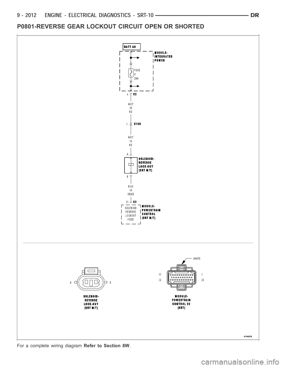
P0801-REVERSE GEAR LOCKOUT CIRCUIT OPEN OR SHORTED
For a complete wiring diagramRefer to Section 8W.