Page 1504 of 5267
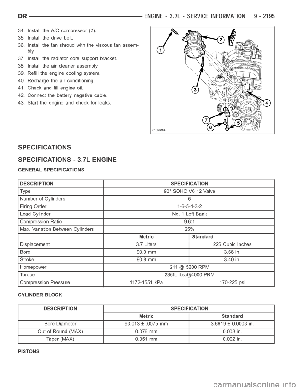
34. Install the A/C compressor (2).
35. Install the drive belt.
36. Install the fan shroud with the viscous fan assem-
bly.
37. Install the radiator core support bracket.
38. Install the air cleaner assembly.
39. Refill the engine cooling system.
40. Recharge the air conditioning.
41. Check and fill engine oil.
42. Connect the battery negative cable.
43. Start the engine and check for leaks.
SPECIFICATIONS
SPECIFICATIONS - 3.7L ENGINE
GENERAL SPECIFICATIONS
DESCRIPTION SPECIFICATION
Type 90°SOHCV612Valve
Number of Cylinders 6
Firing Order 1-6-5-4-3-2
Lead Cylinder No. 1 Left Bank
Compression Ratio 9.6:1
Max. Variation Between Cylinders 25%
Metric Standard
Displacement 3.7 Liters 226 Cubic Inches
Bore 93.0 mm 3.66 in.
Stroke 90.8 mm 3.40 in.
Horsepower 211 @ 5200 RPM
Torque 236ft. lbs.@4000 PRM
Compression Pressure 1172-1551 kPa 170-225 psi
CYLINDER BLOCK
DESCRIPTION SPECIFICATION
Metric Standard
Bore Diameter 93.013 ± .0075 mm 3.6619 ± 0.0003 in.
Out of Round (MAX) 0.076 mm 0.003 in.
Taper (MAX) 0.051 mm 0.002 in.
PISTONS
Page 1509 of 5267
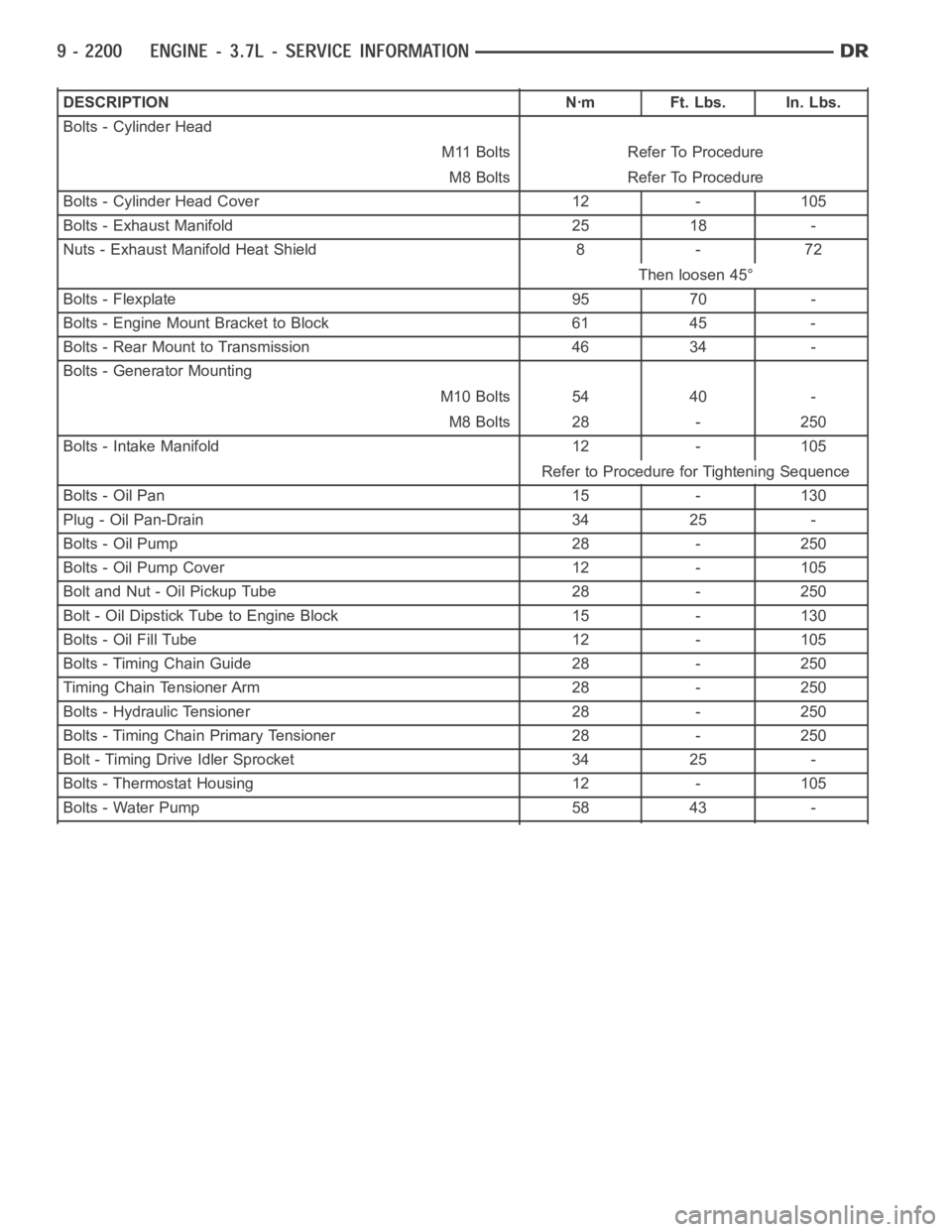
DESCRIPTION Nꞏm Ft. Lbs. In. Lbs.
Bolts - Cylinder Head
M11 Bolts Refer To Procedure
M8 Bolts Refer To Procedure
Bolts - Cylinder Head Cover 12 - 105
Bolts - Exhaust Manifold 25 18 -
Nuts - Exhaust Manifold Heat Shield 8 - 72
Then loosen 45°
Bolts - Flexplate 95 70 -
Bolts - Engine Mount Bracket to Block 61 45 -
Bolts - Rear Mount to Transmission 46 34 -
Bolts - Generator Mounting
M10 Bolts 54 40 -
M8 Bolts 28 - 250
Bolts - Intake Manifold 12 - 105
Refer to Procedure for Tightening Sequence
Bolts - Oil Pan 15 - 130
Plug - Oil Pan-Drain 34 25 -
Bolts - Oil Pump 28 - 250
Bolts - Oil Pump Cover 12 - 105
Bolt and Nut - Oil Pickup Tube 28 - 250
Bolt - Oil Dipstick Tube to Engine Block 15 - 130
Bolts - Oil Fill Tube 12 - 105
Bolts - Timing Chain Guide 28 - 250
Timing Chain Tensioner Arm 28 - 250
Bolts - Hydraulic Tensioner 28 - 250
Bolts - Timing Chain Primary Tensioner 28 - 250
Bolt - Timing Drive Idler Sprocket 34 25 -
Bolts - Thermostat Housing 12 - 105
Bolts - Water Pump 58 43 -
Page 1516 of 5267
INSTALLATION
1. Install filter element into housing.
2. Position housing cover into housing locating tabs.
3. Pry up 4 spring clips and lock cover to housing.
4. Install air duct to air cleaner cover and tighten hose clamp to 3 Nꞏm (30 in.lbs.)torque.
5. If any other hose clamps were removed from air intake system, tighten themto3.4Nꞏm(30in.lbs.)torque.
6. If any bolts were removed from air resonator housing or air intake tubing, tighten them to 4.5 Nꞏm (40 in. lbs.)
torque.
Page 1518 of 5267
7. Remove the master cylinder and booster assembly (Refer to 5 - BRAKES/HYDRAULIC/MECHANICAL/POWER
BRAKE BOOSTER - REMOVAL).
8. Remove the cylinder head cover (Refer to 9 - ENGINE/CYLINDER HEAD/CYLINDER HEAD COVER(S) -
REMOVAL).
9. Remove the fan shroud and fan blade assembly
(Refer to 7 - COOLING/ENGINE/RADIATOR FAN -
REMOVAL).
10. Remove accessory drive belt (Refer to 7 - COOL-
ING/ACCESSORY DRIVE/DRIVE BELTS -
REMOVAL).
11. Remove the power steering pump and set aside.
12. Rotate the crankshaft until the damper timing
mark is aligned with TDC indicator mark (2).
13. Verify the V6 mark on the camshaft sprocket is at the 12 o’clock position. Rotate the crankshaft one turn if
necessary.
14. Remove the crankshaft damper (Refer to 9 - ENGINE/ENGINE BLOCK/VIBRATION DAMPER - REMOVAL).
15. Remove the timing chain cover (Refer to 9 - ENGINE/VALVE TIMING/TIMINGBELT / CHAIN COVER(S) -
REMOVAL).
Page 1519 of 5267
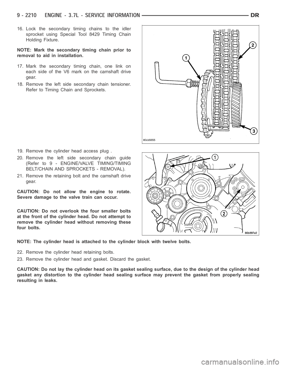
16. Lock the secondary timing chains to the idler
sprocket using Special Tool 8429 Timing Chain
Holding Fixture.
NOTE: Mark the secondary timing chain prior to
removal to aid in installation.
17. Mark the secondary timing chain, one link on
each side of the V6 mark on the camshaft drive
gear.
18. Remove the left side secondary chain tensioner.
Refer to Timing Chain and Sprockets.
19. Remove the cylinder head access plug .
20. Remove the left side secondary chain guide
(Refer to 9 - ENGINE/VALVE TIMING/TIMING
BELT/CHAIN AND SPROCKETS - REMOVAL).
21. Remove the retaining bolt and the camshaft drive
gear.
CAUTION: Do not allow the engine to rotate.
Severe damage to the valve train can occur.
CAUTION: Do not overlook the four smaller bolts
at the front of the cylinder head. Do not attempt to
remove the cylinder head without removing these
four bolts.
NOTE: The cylinder head is attached to the cylinder block with twelve bolts.
22. Remove the cylinder head retaining bolts.
23. Remove the cylinder head and gasket. Discard the gasket.
CAUTION: Do not lay the cylinder head on its gasket sealing surface, due to the design of the cylinder head
gasket any distortion to the cylinder head sealing surface may prevent thegasket from properly sealing
resulting in leaks.
Page 1520 of 5267
INSTALLATION
NOTE: The cylinder head bolts are tightened using
a torque plus angle procedure. The bolts must be
examined BEFORE reuse. If the threads are
necked down (2) the bolts should be replaced.
Necking can be checked by holding a straight edge
against the threads. If all the threads do not contact
the scale, the bolt should be replaced .
CAUTION: When cleaning cylinder head and cylin-
der block surfaces, DO NOT use a metal scraper
(1) because the surfaces could be cut or ground.
Use only a wooden or plastic scraper.
1. Clean the cylinder head and cylinder block mating
surfaces.
Page 1521 of 5267
2. Position the new cylinder head gasket on the locat-
ing dowels.
CAUTION: When installing cylinder head, use care
not damage the tensioner arm or the guide arm.
3. Position the cylinder head onto the cylinder block.
Make sure the cylinder head seats fully over the
locating dowels.
NOTE: The four smaller cylinder head mounting
bolts require sealant to be added to them before
installing. Failure to do so may cause leaks.
4. Lubricate the cylinder head bolt threads with clean
engine oil and install the eight M11 bolts.
5. Coat the four M8 cylinder head bolts withMopar
Lock and Seal Adhesivethen install the bolts.
NOTE: The cylinder head bolts are tightened using
an angle torque procedure, however, the bolts are
not a torque-to-yield design.
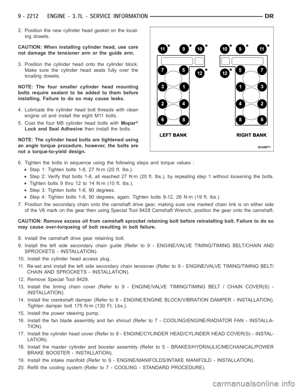
6. Tighten the bolts in sequence using the following steps and torque values:
Step 1: Tighten bolts 1-8, 27 Nꞏm (20 ft. lbs.).
Step 2: Verify that bolts 1-8, all reached 27 Nꞏm (20 ft. lbs.), by repeatingstep 1 without loosening the bolts.
Tightenbolts9thru12to14Nꞏm(10ft.lbs.).
Step 3: Tighten bolts 1-8, 90 degrees.
Step 4: Tighten bolts 1-8, 90 degrees, again. Tighten bolts 9-12, 26 Nꞏm (19ft. lbs.)
7. Position the secondary chain onto the camshaft drive gear, making sure one marked chain link is on either side
of the V6 mark on the gear then using Special Tool 8428 Camshaft Wrench, position the gear onto the camshaft.
CAUTION: Remove excess oil from camshaft sprocket retaining bolt before reinstalling bolt. Failure to do so
may cause over-torqueing of bolt resulting in bolt failure.
8. Install the camshaft drive gear retaining bolt.
9. Install the left side secondary chain guide (Refer to 9 - ENGINE/VALVE TIMING/TIMING BELT/CHAIN AND
SPROCKETS - INSTALLATION).
10. Install the cylinder head access plug.
11. Re-set and install the left side secondary chain tensioner (Refer to 9 -ENGINE/VALVE TIMING/TIMING BELT/
CHAIN AND SPROCKETS - INSTALLATION).
12. Remove Special Tool 8429.
13. Install the timing chain cover (Refer to 9 - ENGINE/VALVE TIMING/TIMING BELT / CHAIN COVER(S) -
INSTALLATION).
14. Install the crankshaft damper (Refer to 9 - ENGINE/ENGINE BLOCK/VIBRATION DAMPER - INSTALLATION).
Tighten damper bolt 175 Nꞏm (130 Ft. Lbs.).
15. Install the power steering pump.
16. Install the fan blade assembly and fan shroud (Refer to 7 - COOLING/ENGINE/RADIATOR FAN - INSTALLA-
TION).
17. Install the cylinder head cover (Refer to 9 - ENGINE/CYLINDER HEAD/CYLINDER HEAD COVER(S) - INSTAL-
LATION).
18. Install the master cylinder and booster assembly (Refer to 5 - BRAKES/HYDRAULIC/MECHANICAL/POWER
BRAKE BOOSTER - INSTALLATION).
19. Install the intake manifold (Refer to 9 - ENGINE/MANIFOLDS/INTAKE MANIFOLD - INSTALLATION).
20. Refill the cooling system (Refer to 7 - COOLING - STANDARD PROCEDURE).
Page 1523 of 5267
CAMSHAFT
DESCRIPTION
The camshafts consist of powdered metal steel lobes which are sinter-bonded to a steel tube. Four bearing journals
are machined into the camshaft. Camshaft end play is controlled by two thrust walls that border the nose piece
journal.
REMOVAL
CAUTION: When the timing chain is removed and the cylinder heads are still installed, DO NOT forcefully
rotate the camshafts or crankshaft independently of each other. Severe valve and/or piston damage can
occur.
CAUTION: When removing the cam sprocket, timing chains or camshaft, Failure to use Special Tool 8379
will result in hydraulic tensioner ratchet over extension, requiring timing chain cover removal to reset the
tensioner ratchet.
1. Remove cylinder head cover (Refer to 9 - ENGINE/CYLINDER HEAD/CYLINDERHEAD COVER(S) -
REMOVAL).
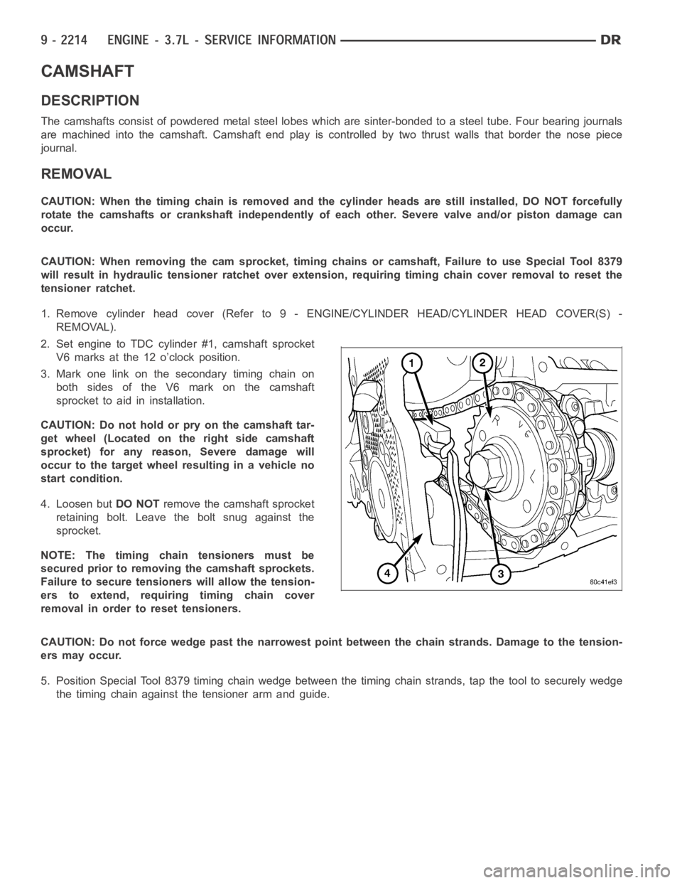
2. Set engine to TDC cylinder #1, camshaft sprocket
V6 marks at the 12 o’clock position.
3. Mark one link on the secondary timing chain on
both sides of the V6 mark on the camshaft
sprocket to aid in installation.
CAUTION: Do not hold or pry on the camshaft tar-
get wheel (Located on the right side camshaft
sprocket) for any reason, Severe damage will
occur to the target wheel resulting in a vehicle no
start condition.
4. Loosen butDO NOTremove the camshaft sprocket
retaining bolt. Leave the bolt snug against the
sprocket.
NOTE: The timing chain tensioners must be
secured prior to removing the camshaft sprockets.
Failure to secure tensioners will allow the tension-
erstoextend,requiringtimingchaincover
removal in order to reset tensioners.
CAUTION: Do not force wedge past the narrowest point between the chain strands. Damage to the tension-
ers may occur.
5. Position Special Tool 8379 timing chain wedge between the timing chain strands, tap the tool to securely wedge
the timing chain against the tensioner arm and guide.