2006 DODGE RAM SRT-10 lock
[x] Cancel search: lockPage 1322 of 5267
When Monitored:
Engine at operating temperature, Engine RPM above 608 rpm’s, and Vehicle Speed above 5 MPH.
Set Condition:
Reverse Gear Lockout Solenoid Control circuit is not in the expected statewhen requested to operate by the
PCM. Note: When Vehicle Speed is less then 5 MPH the PCM provides a ground forthe solenoid which ener-
gizes the solenoid. (Allowing Reverse).
Possible Causes
(A917) FUSED IGNITION SWITCH OUTPUT CIRCUIT
(K333) REVERSE LOCKOUT SOLENOID CONTROL CIRCUIT OPEN
(K333) REVERSE LOCKOUT SOLENOID CONTROL CIRCUIT SHORT TO GROUND
REVERSE LOCKOUT SOLENOID
PCM
Always perform the Pre-Diagnostic Troubleshooting procedure before proceeding. (Refer to 9 - ENGINE -
DIAGNOSIS AND TESTING)
1.GOOD TRIP EQUAL TO ZERO
With the scan tool, read DTCs and record the related Freeze Frame data.
Is the Good Trip Counter displayed and equal to zero?
Ye s>>
Go To 2
No>>
Refer to the INTERMITTENT CONDITION Diagnostic Procedure.
Perform POWERTRAIN VERIFICATION TEST. (Refer to 9 - ENGINE - STANDARD PROCEDURE)
2.(A917) FUSED IGNITION SWITCH OUTPUT CIRCUIT OPEN OR SHORT TO GROUND
Turn the ignition off.
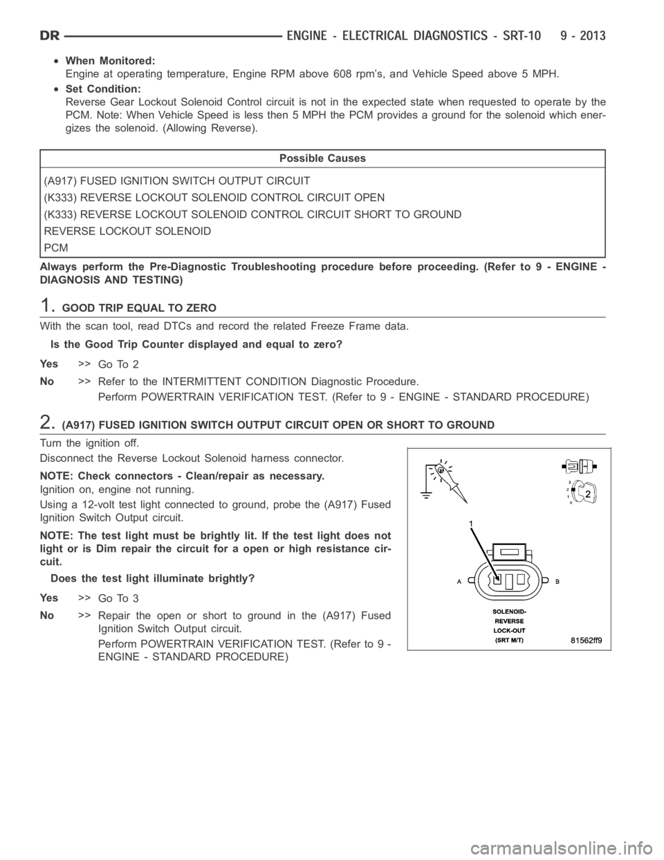
Disconnect the Reverse Lockout Solenoid harness connector.
NOTE: Check connectors - Clean/repair as necessary.
Ignition on, engine not running.
Using a 12-volt test light connected to ground, probe the (A917) Fused
Ignition Switch Output circuit.
NOTE: The test light must be brightly lit. If the test light does not
light or is Dim repair the circuit for a open or high resistance cir-
cuit.
Does the test light illuminate brightly?
Ye s>>
Go To 3
No>>
Repair the open or short to ground in the (A917) Fused
Ignition Switch Output circuit.
Perform POWERTRAIN VERIFICATION TEST. (Refer to 9 -
ENGINE - STANDARD PROCEDURE)
Page 1323 of 5267
3.(K333) REVERSE LOCKOUT SOLENOID CONTROL CIRCUIT OPEN
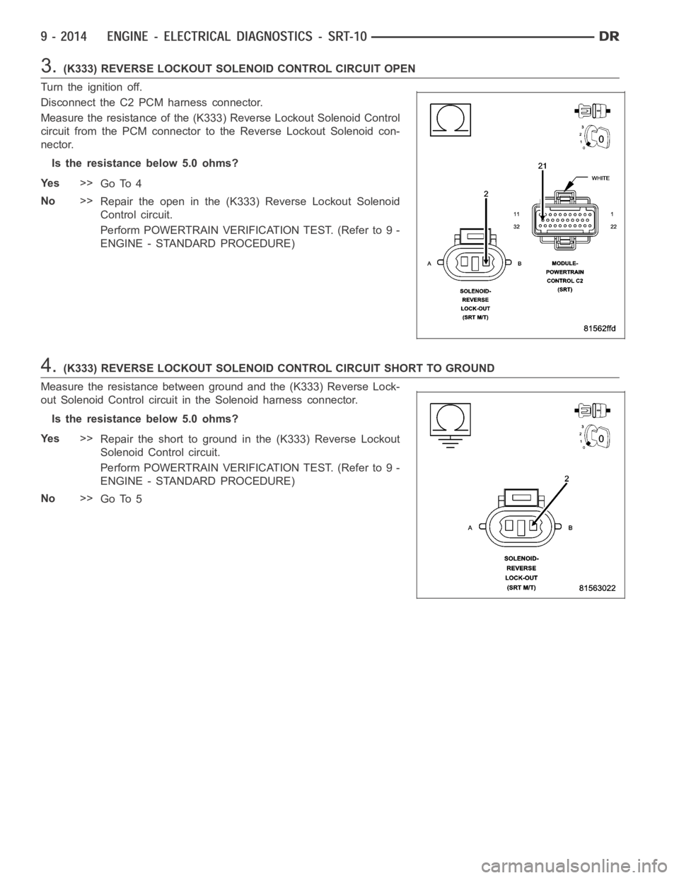
Turn the ignition off.
Disconnect the C2 PCM harness connector.
Measure the resistance of the (K333) Reverse Lockout Solenoid Control
circuit from the PCM connector to the Reverse Lockout Solenoid con-
nector.
Is the resistance below 5.0 ohms?
Ye s>>
Go To 4
No>>
Repair the open in the (K333) Reverse Lockout Solenoid
Control circuit.
Perform POWERTRAIN VERIFICATION TEST. (Refer to 9 -
ENGINE - STANDARD PROCEDURE)
4.(K333) REVERSE LOCKOUT SOLENOID CONTROL CIRCUIT SHORT TO GROUND
Measure the resistance between ground and the (K333) Reverse Lock-
out Solenoid Control circuit in the Solenoid harness connector.
Is the resistance below 5.0 ohms?
Ye s>>
Repair the short to ground in the (K333) Reverse Lockout
Solenoid Control circuit.
Perform POWERTRAIN VERIFICATION TEST. (Refer to 9 -
ENGINE - STANDARD PROCEDURE)
No>>
Go To 5
Page 1324 of 5267
5.REVERSE LOCKOUT SOLENOID
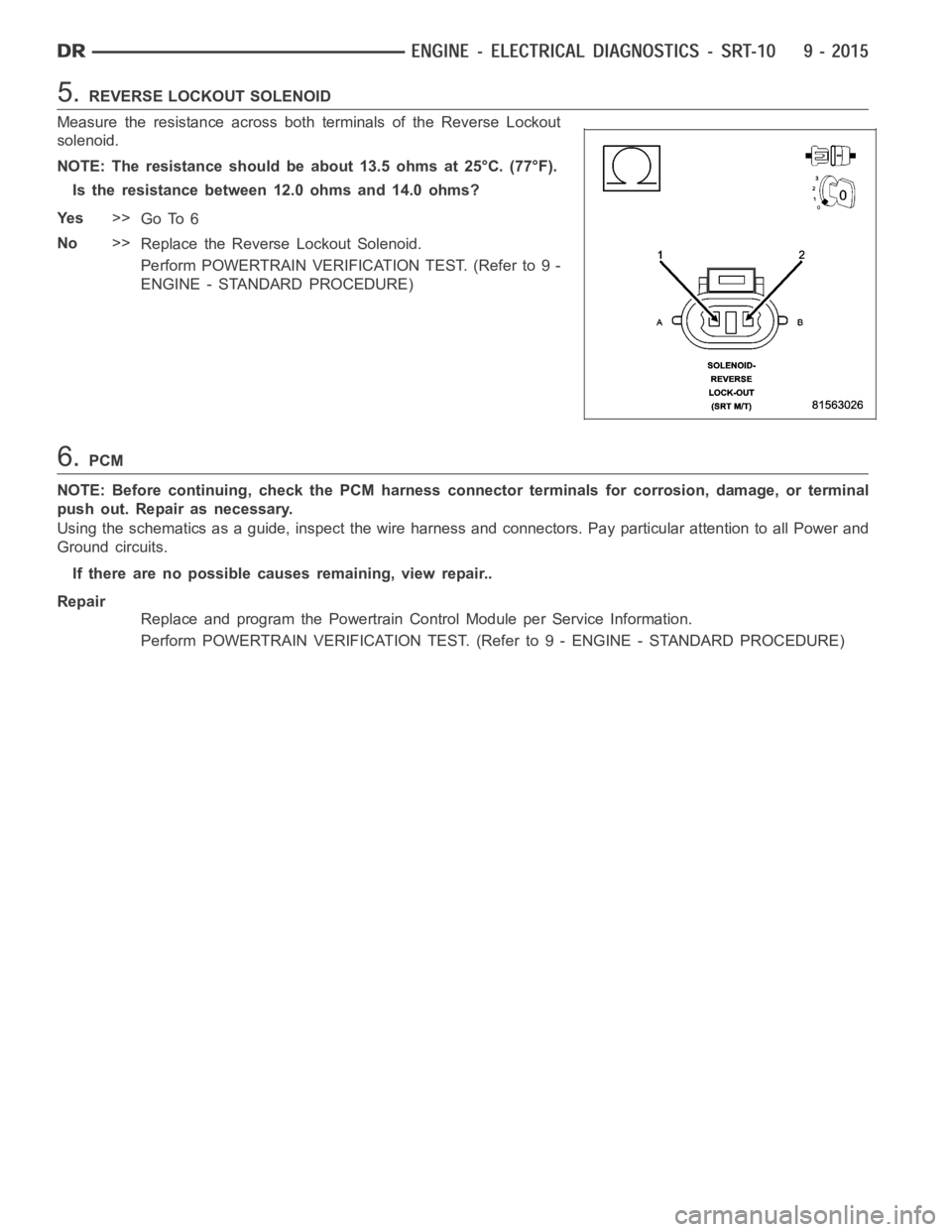
Measure the resistance across both terminals of the Reverse Lockout
solenoid.
NOTE: The resistance should be about 13.5 ohms at 25°C. (77°F).
Is the resistance between 12.0 ohms and 14.0 ohms?
Ye s>>
Go To 6
No>>
Replace the Reverse Lockout Solenoid.
Perform POWERTRAIN VERIFICATION TEST. (Refer to 9 -
ENGINE - STANDARD PROCEDURE)
6.PCM
NOTE: Before continuing, check the PCM harness connector terminals for corrosion, damage, or terminal
push out. Repair as necessary.
Using the schematics as a guide, inspect the wire harness and connectors. Pay particular attention to all Power and
Ground circuits.
If there are no possible causes remaining, view repair..
Repair
Replace and program the Powertrain Control Module per Service Information.
Perform POWERTRAIN VERIFICATION TEST. (Refer to 9 - ENGINE - STANDARD PROCEDURE)
Page 1417 of 5267
3.EVAP PURGE SOLENOID VACUUM LINE
Turn the ignition off.
Inspect the Purge Solenoid Vacuum line that runs from the Evap Purge Solenoid to the throttle body or intake man-
ifold.
Is the vacuum line plugged or kinked?
Ye s>>
Repair or replace the vacuum line from the solenoid to the throttle body / intake manifold.
Perform POWERTRAIN VERIFICATION TEST. (Refer to 9 - ENGINE - STANDARD PROCEDURE)
No>>
Go To 4
NOTE: Reconnect the vacuum line before continuing.
4.CHECKED FOR OTHER BLOCKED HOSES
To continue testing you will need Miller Tool #6872A (Evap System PressurePump) and #8382 (Gas Cap Tester [
]Adapter).
WARNING: The test equipment is designed to be used to pressurize the vehicles Evaporative System only.
Using the equipment in a manner for which it was not designed could be harmful.
WARNING: Keep lit cigarettes, sparks, flames, and other ignition sourcesaway from the test area to prevent
the ignition of explosive gases. Keep the test area well ventilated.
NOTE: The fuel tank should have between 20% and 80% of full to properly test the Evap System.
Attach the power source clip (red) of Miller Tool #6872A to Battery (+) and the ground clip (black) to Battery (-).
Perform the Evaporative System Pressure Pump self test that is specified on the tester cover.
Remove gas cap and install Miller Tool #8382 on the vehicle. Install gas capto Miller Tool #8382. Attach the pres-
sure supply hose from Miller Tool #6872A to the fitting on #8382.
Disconnect the vacuum supply hose at the Leak Detection Pump.
Connect and apply a continuous vacuum supply (i.e. 20”Hg) to the Leak Detection Pump. A vacuum pump such as
an A/C Recovery unit works well.
Ignition on, engine not running.
With the scan tool perform the “Leak Detect Pump Test”. Follow the scan toolinstructions and then press ENTER.
Select#3–HOLDPSI.
On Miller Tool #6872A, set the Pressure/Hold switch to Open and set the Ventswitch to Closed. Turn the pump
timer On and watch the gauge.
When the gauge pressure reaches 14”H2O, turn the Pressure/Hold Valve to Closed.
Turn the pump timer off.
Disconnect the hose at the Evap Canister that goes to the Fuel Tank.
Did the pressure drop when the hose was disconnected?
Ye s>>
Go To 5
No>>
Repair the obstruction in the Evap System between the Evap Canister and thefuel tank.
Perform POWERTRAIN VERIFICATION TEST. (Refer to 9 - ENGINE - STANDARD PROCEDURE)
5.EVAP CANISTER FUNCTION
NOTE: Connect all previously disconnected hoses.
Re-pressurize the Evap System. On Miller Tool #6872A, set the Pressure/Hold switch to Open and set the Vent
switch to Closed.
Turn the pump timer On and watch the gauge.
When the gauge pressure reaches 14” H2O, turn the Pressure/Hold Valve Closed.
Turn the pump timer off.
Page 1467 of 5267
Possible Causes
REVERSE LOCKOUT SOLENOID STUCK
Always perform the Pre-Diagnostic Troubleshooting procedure before proceeding. (Refer to 9 - ENGINE -
DIAGNOSIS AND TESTING)
Diagnostic Test
1.REVERSE LOCKOUT SOLENOID STUCK
Check for a mechanically stuck Reverse Lockout Solenoid. This will not seta DTC in the PCM, but will prevent
reverse gear engagement.
Is the solenoid stuck?
Ye s>>
Replace the Reverse Lockout Solenoid.
No>>
Te s t C o m p l e t e
Page 1481 of 5267
B2277–CAN GATEWAY INTERNAL (GATEWAY)
For a complete wiring diagramRefer to Section 8W.
When Monitored:
With the ignition on.
Set Condition:
If the Gateway Module detects an internal failure.
Possible Causes
GATEWAY MODULE
Diagnostic Test
1.REPLACE THE GATEWAY MODULE
Repair
Replace the Gateway Module in accordance with the Service Information.
Perform GATEWAY VERIFICATION TEST - VER 1. (Refer to 9 - ENGINE - STANDARD PROCEDURE).
U0001–CAN C BUS CIRCUIT (GATEWAY)
For a complete wiring diagramRefer to Section 8W.
When Monitored:
With the ignition on.
Set Condition:
If the Gateway Module detects a short in either CAN C Bus circuit.
Refer to U0001-CAN C BUS CIRCUIT(in 8 - ELECTRICAL/ELECTRONIC CONTROL MODULES - DIAGNOSIS
AND TESTING)for the diagnostic test procedure.
U0002–CAN C BUS PERFORMANCE (GATEWAY)
For a complete wiring diagramRefer to Section 8W.
When Monitored:
With the ignition on.
Set Condition:
If the Gateway Module detects a short in either CAN C Bus circuit.
Refer to U0001-CAN C BUS CIRCUIT(in 8 - ELECTRICAL/ELECTRONIC CONTROL MODULES - DIAGNOSIS
AND TESTING)for the diagnostic test procedure.
U0100–LOST COMMUNICATION WITH ECM/PCM (GATEWAY)
For a complete wiring diagramRefer to Section 8W.
When Monitored:
With the ignition on.
Set Condition:
If the Gateway Module looses communication with the Powertrain Control Module (PCM).
Refer to U0100-LOST COMMUNICATION WITH ECM/PCM(in 8 - ELECTRICAL/ELECTRONIC CONTROL MOD-
ULES - DIAGNOSIS AND TESTING)for the diagnostic test procedure.
U0121–LOST COMMUNICATION WITH ANTI-LOCK BRAKE MODULE (GATEWAY)
For a complete wiring diagramRefer to Section 8W.
Page 1482 of 5267
When Monitored:
With the ignition on.
Set Condition:
If the Gateway Module looses communication with the Anti-Lock Brake Module.
Refer to U0121-LOST COMMUNICATION WITH ANTI-LOCK BRAKE MODULE(in 8 - ELECTRICAL/ELECTRONIC
CONTROL MODULES - DIAGNOSIS AND TESTING)for the diagnostic test procedure.
U0155–LOST COMMUNICATION WITH CLUSTER/CCN (GATEWAY)
For a complete wiring diagramRefer to Section 8W.
When Monitored:
With the ignition on.
Set Condition:
If the Gateway Module looses communication with the Cluster (CCN).
Refer to U0155-LOST COMMUNICATION WITH CLUSTER/CCN(in 8 - ELECTRICAL/ELECTRONIC CONTROL
MODULES - DIAGNOSIS AND TESTING)for the diagnostic test procedure.
U0168–LOST COMMUNICATION WITHVEHICLE SECURITY CONTROL MODULE -
SKREEM/WCM (GATEWAY)
For a complete wiring diagramRefer to Section 8W.
When Monitored:
With the ignition on.
Set Condition:
If the Gateway Module looses communication with the Vehicle Security Control Module (SKREEM/WCM).
Refer to U0168-LOST COMMUNICATION WITH VEHICLE SECURITY CONTROL MODULE (SKREEM/WCM)(in 8
- ELECTRICAL/ELECTRONIC CONTROL MODULES - DIAGNOSIS AND TESTING)for the diagnostic test proce-
dure.
STANDARD PROCEDURE
Page 1487 of 5267
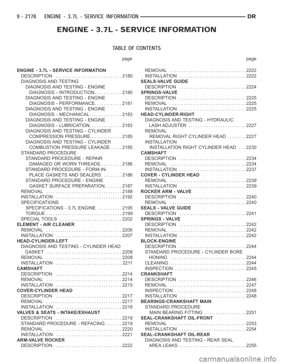
page page
ENGINE - 3.7L - SERVICE INFORMATION
DESCRIPTION ............................. 2180
DIAGNOSIS AND TESTING
DIAGNOSIS AND TESTING - ENGINE
DIAGNOSIS - INTRODUCTION............. 2180
DIAGNOSIS AND TESTING - ENGINE
DIAGNOSIS - PERFORMANCE............. 2181
DIAGNOSIS AND TESTING - ENGINE
DIAGNOSIS - MECHANICAL............... 2183
DIAGNOSIS AND TESTING - ENGINE
DIAGNOSIS - LUBRICATION............... 2183
DIAGNOSIS AND TESTING - CYLINDER
COMPRESSION PRESSURE............... 2185
DIAGNOSIS AND TESTING - CYLINDER
COMBUSTION PRESSURE LEAKAGE...... 2185
STANDARD PROCEDURE
STANDARD PROCEDURE - REPAIR
DAMAGED OR WORN THREADS.......... 2186
STANDARD PROCEDURE - FORM-IN-
PLACE GASKETS AND SEALERS.......... 2186
STANDARD PROCEDURE - ENGINE
GASKET SURFACE PREPARATION........ 2187
REMOVAL ................................. 2188
INSTALLATION ............................. 2192
SPECIFICATIONS
SPECIFICATIONS - 3.7L ENGINE .......... 2195
TORQUE ................................. 2199
SPECIAL TOOLS ........................... 2202
ELEMENT - AIR CLEANER
REMOVAL ................................. 2206
INSTALLATION ............................. 2207
HEAD-CYLINDER-LEFT
DIAGNOSIS AND TESTING - CYLINDER HEAD
GASKET . . ............................... 2208
REMOVAL ................................. 2208
INSTALLATION ............................. 2211
CAMSHAFT
DESCRIPTION ............................. 2214
REMOVAL ................................. 2214
INSTALLATION ............................. 2215
COVER-CYLINDER HEAD
DESCRIPTION ............................. 2217
REMOVAL ................................. 2217
INSTALLATION ............................. 2218
VALVES & SEATS - INTAKE/EXHAUST
DESCRIPTION ............................. 2219
STANDARD PROCEDURE - REFACING ....... 2219
REMOVAL ................................. 2220
INSTALLATION ............................. 2221
ARM-VALVE ROCKER
DESCRIPTION ............................. 2222REMOVAL ................................. 2222
INSTALLATION ............................. 2222
SEALS-VALVE GUIDE
DESCRIPTION ............................. 2224
SPRINGS-VALVE
DESCRIPTION ............................. 2225
REMOVAL ................................. 2225
INSTALLATION ............................. 2225
HEAD-CYLINDER-RIGHT
DIAGNOSIS AND TESTING - HYDRAULIC
LASH ADJUSTER ......................... 2227
REMOVAL
REMOVAL RIGHT CYLINDER HEAD ........ 2227
INSTALLATION
INSTALLATION RIGHT CYLINDER HEAD . . . 2230
CAMSHAFT
DESCRIPTION ............................. 2234
REMOVAL ................................. 2234
INSTALLATION ............................. 2237
COVER - CYLINDER HEAD
REMOVAL ................................. 2239
INSTALLATION ............................. 2239
ROCKER ARM - VALVE
DESCRIPTION ............................. 2240
REMOVAL ................................. 2240
SEALS - VALVE GUIDE
DESCRIPTION ............................. 2241
SPRINGS - VALVE
DESCRIPTION ............................. 2242
REMOVAL ................................. 2242
INSTALLATION ............................. 2242
BLOCK-ENGINE
DESCRIPTION ............................. 2244
STANDARD PROCEDURE - CYLINDER BORE
HONING ................................. 2244
CLEANING ................................. 2244
INSPECTION............................... 2245
CRANKSHAFT
DESCRIPTION ............................. 2246
REMOVAL ................................. 2247
INSPECTION............................... 2248
INSTALLATION ............................. 2248
BEARINGS-CRANKSHAFT MAIN
STANDARD PROCEDURE
MAIN BEARING FITTING.................. 2251
SEAL-CRANKSHAFT OIL-FRONT
REMOVAL ................................. 2253
INSTALLATION ............................. 2254
SEAL-CRANKSHAFT OIL-REAR
DIAGNOSIS AND TESTING - REAR SEAL
AREA LEAKS ............................. 2255