2006 DODGE RAM SRT-10 service
[x] Cancel search: servicePage 3361 of 5267
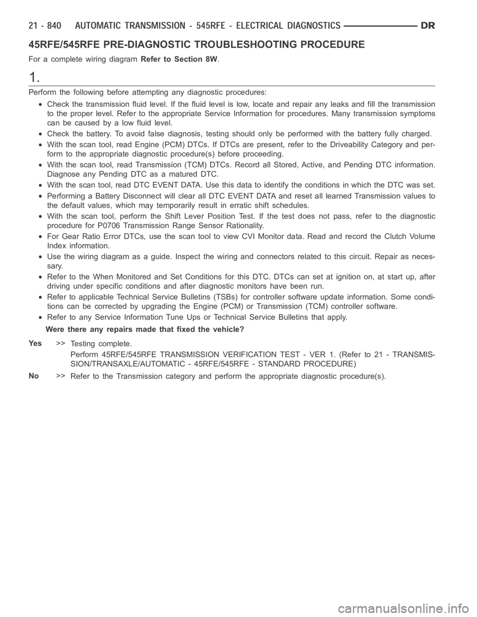
45RFE/545RFE PRE-DIAGNOSTIC TROUBLESHOOTING PROCEDURE
For a complete wiring diagramRefer to Section 8W.
1.
Perform the following before attempting any diagnostic procedures:
Check the transmission fluid level. Ifthe fluid level is low, locate and repair any leaks and fill the transmission
to the proper level. Refer to the appropriate Service Information for procedures. Many transmission symptoms
can be caused by a low fluid level.
Check the battery. To avoid false diagnosis, testing should only be performed with the battery fully charged.
With the scan tool, read Engine (PCM) DTCs. If DTCs are present, refer to theDriveability Category and per-
form to the appropriate diagnostic procedure(s) before proceeding.
With the scan tool, read Transmission (TCM) DTCs. Record all Stored, Active, and Pending DTC information.
Diagnose any Pending DTC as a matured DTC.
With the scan tool, read DTC EVENT DATA.Use this data to identify the conditions in which the DTC was set.
Performing a Battery Disconnect will clear all DTC EVENT DATA and reset alllearned Transmission values to
the default values, which may temporarily result in erratic shift schedules.
With the scan tool, perform the Shift Lever Position Test. If the test does not pass, refer to the diagnostic
procedure for P0706 Transmission Range Sensor Rationality.
For Gear Ratio Error DTCs, use the scan tool to view CVI Monitor data. Read and record the Clutch Volume
Index information.
Use the wiring diagram as a guide. Inspect the wiring and connectors related to this circuit. Repair as neces-
sary.
Refer to the When Monitored and Set Conditions for this DTC. DTCs can set at ignition on, at start up, after
driving under specific conditions and after diagnostic monitors have beenrun.
Refer to applicable Technical Service Bulletins (TSBs) for controller software update information. Some condi-
tions can be corrected by upgrading the Engine (PCM) or Transmission (TCM)controller software.
Refer to any Service Information Tune Ups or Technical Service Bulletins that apply.
Were there any repairs made that fixed the vehicle?
Ye s>>
Testing complete.
Perform 45RFE/545RFE TRANSMISSION VERIFICATION TEST - VER 1. (Refer to 21- TRANSMIS-
SION/TRANSAXLE/AUTOMATIC - 45RFE/545RFE - STANDARD PROCEDURE)
No>>
Refer to the Transmission category and perform the appropriate diagnostic procedure(s).
Page 3362 of 5267
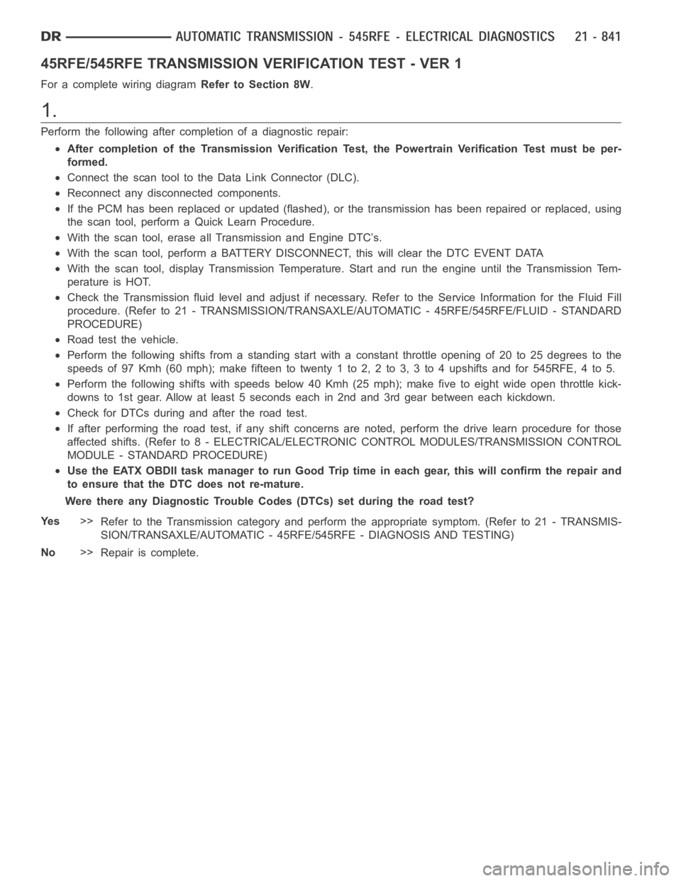
45RFE/545RFE TRANSMISSION VERIFICATION TEST - VER 1
For a complete wiring diagramRefer to Section 8W.
1.
Perform the following after completion of a diagnostic repair:
After completion of the Transmission Verification Test, the Powertrain Verification Test must be per-
formed.
Connect the scan tool to the Data Link Connector (DLC).
Reconnect any disconnected components.
If the PCM has been replaced or updated (flashed), or the transmission has been repaired or replaced, using
the scan tool, perform a Quick Learn Procedure.
With the scan tool, erase all Transmission and Engine DTC’s.
With the scan tool, perform a BATTERY DISCONNECT, this will clear the DTC EVENT DATA
With the scan tool, display Transmission Temperature. Start and run the engine until the Transmission Tem-
perature is HOT.
Check the Transmission fluid level and adjust if necessary. Refer to the Service Information for the Fluid Fill
procedure. (Refer to 21 - TRANSMISSION/TRANSAXLE/AUTOMATIC - 45RFE/545RFE/FLUID - STANDARD
PROCEDURE)
Road test the vehicle.
Perform the following shifts from a standing start with a constant throttle opening of 20 to 25 degrees to the
speeds of 97 Kmh (60 mph); make fifteen to twenty 1 to 2, 2 to 3, 3 to 4 upshifts andfor545RFE,4to5.
Perform the following shifts with speeds below 40 Kmh (25 mph); make five toeight wide open throttle kick-
downs to 1st gear. Allow at least 5 seconds each in 2nd and 3rd gear between each kickdown.
Check for DTCs during and after the road test.
If after performing the road test, if any shift concerns are noted, performthe drive learn procedure for those
affected shifts. (Refer to 8 - ELECTRICAL/ELECTRONIC CONTROL MODULES/TRANSMISSION CONTROL
MODULE - STANDARD PROCEDURE)
Use the EATX OBDII task manager to run Good Trip time in each gear, this will confirm the repair and
to ensure that the DTC does not re-mature.
Were there any Diagnostic Trouble Codes (DTCs) set during the road test?
Ye s>>
Refer to the Transmission category and perform the appropriate symptom. (Refer to 21 - TRANSMIS-
SION/TRANSAXLE/AUTOMATIC - 45RFE/545RFE - DIAGNOSIS AND TESTING)
No>>
Repair is complete.
Page 3363 of 5267
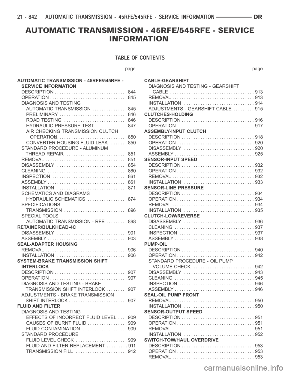
page page
AUTOMATIC TRANSMISSION - 45RFE/545RFE -
SERVICE INFORMATION
DESCRIPTION ............................... 844
OPERATION ................................. 845
DIAGNOSIS AND TESTING
AUTOMATIC TRANSMISSION ............... 845
PRELIMINARY ............................. 846
ROAD TESTING ........................... 846
HYDRAULIC PRESSURE TEST............. 847
AIR CHECKING TRANSMISSION CLUTCH
OPERATION............................... 850
CONVERTER HOUSING FLUID LEAK ....... 850
STANDARD PROCEDURE - ALUMINUM
THREAD REPAIR .......................... 851
REMOVAL ................................... 851
DISASSEMBLY .............................. 854
CLEANING .................................. 860
INSPECTION ................................ 861
ASSEMBLY .................................. 861
INSTALLATION .............................. 871
SCHEMATICS AND DIAGRAMS
HYDRAULIC SCHEMATICS ................. 874
SPECIFICATIONS
TRANSMISSION ........................... 896
SPECIAL TOOLS
AUTOMATIC TRANSMISSION - RFE ......... 898
RETAINER/BULKHEAD-4C
DISASSEMBLY .............................. 901
ASSEMBLY .................................. 903
SEAL-ADAPTER HOUSING
REMOVAL ................................... 906
INSTALLATION .............................. 906
SYSTEM-BRAKE TRANSMISSION SHIFT
INTERLOCK
DESCRIPTION ............................... 907
OPERATION ................................. 907
DIAGNOSIS AND TESTING - BRAKE
TRANSMISSION SHIFT INTERLOCK ......... 907
ADJUSTMENTS - BRAKE TRANSMISSION
SHIFT INTERLOCK ......................... 907
FLUID AND FILTER
DIAGNOSIS AND TESTING
EFFECTS OF INCORRECT FLUID LEVEL.... 909
CAUSES OF BURNT FLUID ................. 909
FLUID CONTAMINATION ................... 909
STANDARD PROCEDURE
FLUID LEVEL CHECK . ..................... 909
FLUID AND FILTER REPLACEMENT ......... 911
TRANSMISSION FILL ...................... 912CABLE-GEARSHIFT
DIAGNOSIS AND TESTING - GEARSHIFT
CABLE .................................... 913
REMOVAL ................................... 913
INSTALLATION .............................. 914
ADJUSTMENTS - GEARSHIFT CABLE ......... 915
CLUTCHES-HOLDING
DESCRIPTION ............................... 916
OPERATION ................................. 917
ASSEMBLY-INPUT CLUTCH
DESCRIPTION ............................... 918
OPERATION ................................. 920
DISASSEMBLY .............................. 920
ASSEMBLY .................................. 925
SENSOR-INPUT SPEED
DESCRIPTION ............................... 932
OPERATION ................................. 932
REMOVAL ................................... 932
INSTALLATION .............................. 933
SENSOR-LINE PRESSURE
DESCRIPTION ............................... 934
OPERATION ................................. 934
REMOVAL ................................... 934
INSTALLATION .............................. 935
CLUTCH-LOW/REVERSE
DISASSEMBLY .............................. 936
CLEANING .................................. 937
INSPECTION . . .............................. 937
ASSEMBLY .................................. 938
PUMP-OIL
DESCRIPTION ............................... 940
OPERATION ................................. 942
STANDARD PROCEDURE - OIL PUMP
VOLUME CHECK .......................... 942
DISASSEMBLY .............................. 943
CLEANING .................................. 945
INSPECTION . . .............................. 946
ASSEMBLY .................................. 946
SEAL-OIL PUMP FRONT
REMOVAL ................................... 950
INSTALLATION .............................. 950
SENSOR-OUTPUT SPEED
DESCRIPTION ............................... 951
OPERATION ................................. 951
REMOVAL ................................... 951
INSTALLATION .............................. 952
SWITCH-TOW/HAUL OVERDRIVE
DESCRIPTION ............................... 953
OPERATION ................................. 953
REMOVAL ................................... 953
Page 3365 of 5267
AUTOMATIC TRANSMISSION - 45RFE/545RFE-SERVICEINFORMATION
DESCRIPTION
The 45RFE/545RFE automatic transmissions is a sophisticated, multi-range, electronically controlled transmission
which combines optimized gear ratios for responsive performance, state of the art efficiency features and low NVH.
Other features include driver adaptive shifting and three planetary gearsets to provide wide ratio capability with
precise ratio steps for optimum driveability. The three planetary gear sets also make available a unique alternate
second gear ratio. The primary 2nd gear ratio fits between 1st and 3rd gearsfor normal through-gear accelerations.
The alternate second gear ratio (2prime) allows smoother 4-2 kickdowns athigh speeds to provide 2nd gear pass-
ing performance over a wider highway cruising range.
The hydraulic portion of the transmission consists of the transmission fluid, fluid passages, hydraulic valves, and
various line pressure control components.
The primary mechanical components of the transmission consist of the following:
Three multiple disc input clutches
Three multiple disc holding clutches
Five hydraulic accumulators
Three planetary gear sets
Dual Stage Hydraulic oil pump
Valve body
Solenoid pack
The Transmission Control Module (TCM) is the “heart” or “brain” of the electronic control system and relies on infor-
mation from various direct and indirect inputs (sensors, switches, etc.)to determine driver demand and vehicle oper-
ating conditions. Depending on the vehicle configuration, the TCM may be astandalone module or it it may be
housed along with the Powertrain Control Module (PCM) in a single module. With this information, the TCM can
calculate and perform timely and quality shifts through various output orcontrol devices (solenoid pack, transmission
control relay, etc.).
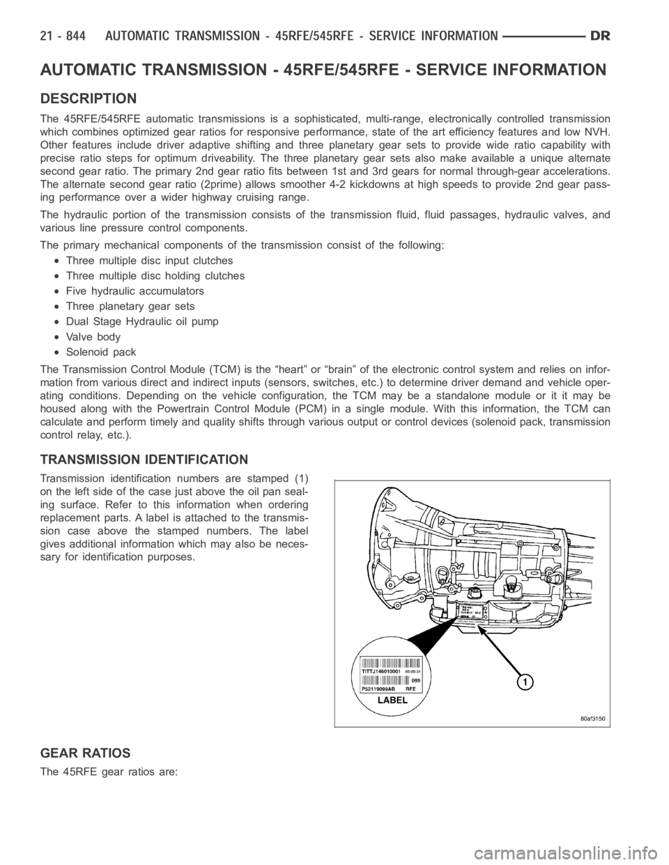
TRANSMISSION IDENTIFICATION
Transmission identification numbers are stamped (1)
on the left side of the case just above the oil pan seal-
ing surface. Refer to this information when ordering
replacement parts. A label is attached to the transmis-
sion case above the stamped numbers. The label
gives additional information which may also be neces-
sary for identification purposes.
GEAR RATIOS
The 45RFE gear ratios are:
Page 3374 of 5267
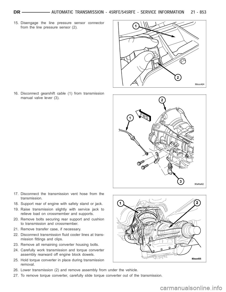
15. Disengage the line pressure sensor connector
from the line pressure sensor (2).
16. Disconnect gearshift cable (1) from transmission
manual valve lever (3).
17. Disconnect the transmission vent hose from the
transmission.
18. Support rear of engine with safety stand or jack.
19. Raise transmission slightly with service jack to
relieve load on crossmember and supports.
20. Remove bolts securing rear support and cushion
to transmission and crossmember.
21. Remove transfer case, if necessary.
22. Disconnect transmission fluid cooler lines at trans-
mission fittings and clips.
23. Remove all remaining converter housing bolts.
24. Carefully work transmission and torque converter
assembly rearward off engine block dowels.
25. Hold torque converter in place during transmission
removal.
26. Lower transmission (2) and remove assembly from under the vehicle.
27. To remove torque converter, carefully slide torque converter out of the transmission.
Page 3430 of 5267
FLUID AND FILTER
DIAGNOSIS AND TESTING
EFFECTS OF INCORRECT FLUID LEVEL
Alowfluidlevelallowsthepumptotakeinairalongwiththefluid.Airinthe fluid will cause fluid pressures to be
low and develop slower than normal. If the transmission is overfilled, thegears churn the fluid into foam. This aer-
ates the fluid and causing the same conditions occurring with a low level. In either case, air bubbles cause fluid
overheating, oxidation, and varnish buildup which interferes with valveand clutch operation. Foaming also causes
fluid expansion which can result in fluid overflow from the transmission vent or fill tube. Fluid overflow can easily be
mistaken for a leak if inspection is not careful.
CAUSES OF BURNT FLUID
Burnt, discolored fluid is a result of overheating which has three primarycauses.
1. Internal clutch slippage, usually caused by low line pressure, inadequate clutch apply pressure, or clutch seal
failure.
2. A result of restricted fluid flow through the main and/or auxiliary cooler. This condition is usually the result of a
faulty or improperly installed drainback valve, a damaged oil cooler, or severe restrictions in the coolers and lines
caused by debris or kinked lines.
3. Heavy duty operation with a vehicle not properly equipped for this type of operation. Trailer towing or similar high
load operation will overheat the transmission fluid if the vehicle is improperly equipped. Such vehicles should
have an auxiliary transmission fluid cooler, a heavy duty cooling system,and the engine/axle ratio combination
needed to handle heavy loads.
FLUID CONTAMINATION
Transmission fluid contamination is generally a result of:
adding incorrect fluid
failure to clean dipstick and fill tube when checking level
engine coolant entering the fluid
internal failure that generates debris
overheat that generates sludge (fluid breakdown)
failure to replace contaminated converter after repair
The use of non-recommended fluids can result in transmission failure. Theusual results are erratic shifts, slippage,
abnormal wear and eventual failure due to fluid breakdown and sludge formation. Avoid this condition by using rec-
ommended fluids only.
The dipstick cap and fill tube should be wiped clean before checking fluid level. Dirt, grease and other foreign mate-
rial on the cap and tube could fall into the tube if not removed beforehand. Take the time to wipe the cap and tube
clean before withdrawing the dipstick.
Engine coolant in the transmission fluid is generally caused by a cooler malfunction. The only remedy is to replace
the radiator as the cooler in the radiator is not a serviceable part. If coolant has circulated through the transmission,
an overhaul is necessary.
The torque converter should also be replaced whenever a failure generatessludge and debris. This is necessary
because normal converter flushing procedures will not remove all contaminants.
STANDARD PROCEDURE
FLUID LEVEL CHECK
Low fluid level can cause a variety of conditions because it allows the pumpto take in air along with the fluid. As
in any hydraulic system, air bubbles make the fluid spongy, therefore, pressures will be low and build up slowly.
Improper filling can also raise the fluid level too high. When the transmssion has too much fluid, the geartrain
churns up foam and cause the same conditions which occur with a low fluid level.
Page 3432 of 5267
FLUID AND FILTER REPLACEMENT
For proper service intervals (Refer to LUBRICATION & MAINTENANCE/MAINTENANCE SCHEDULES - DESCRIP-
TION).
REMOVAL
1. Hoist and support vehicle on safety stands.
2. Place a large diameter shallow drain pan beneath the transmission pan.
3. Remove bolts holding front and sides of pan to transmission.
4. Loosen bolts holding rear of pan to transmission.
5. Slowly separate front of pan away from transmission allowing the fluid to drain into drain pan.
6. Hold up pan and remove remaining bolts holding pan to transmission.
7. While holding pan level, lower pan away from transmission.
8. Pour remaining fluid in pan into drain pan.
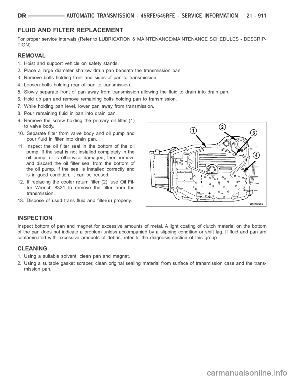
9. Remove the screw holding the primary oil filter (1)
to valve body.
10. Separate filter from valve body and oil pump and
pour fluid in filter into drain pan.
11. Inspect the oil filter seal in the bottom of the oil
pump. If the seal is not installed completely in the
oil pump, or is otherwise damaged, then remove
and discard the oil filter seal from the bottom of
the oil pump. If the seal is installed correctly and
is in good condition, it can be reused.
12. If replacing the cooler return filter (2), use Oil Fil-
ter Wrench 8321 to remove the filter from the
transmission.
13. Dispose of used trans fluid and filter(s) properly.
INSPECTION
Inspect bottom of pan and magnet for excessive amounts of metal. A light coating of clutch material on the bottom
of the pan does not indicate a problem unless accompanied by a slipping condition or shift lag. If fluid and pan are
contaminated with excessive amounts of debris, refer to the diagnosis section of this group.
CLEANING
1. Using a suitable solvent, clean pan and magnet.
2. Using a suitable gasket scraper, clean original sealing material from surface of transmission case and the trans-
mission pan.
Page 3478 of 5267
DISASSEMBLY
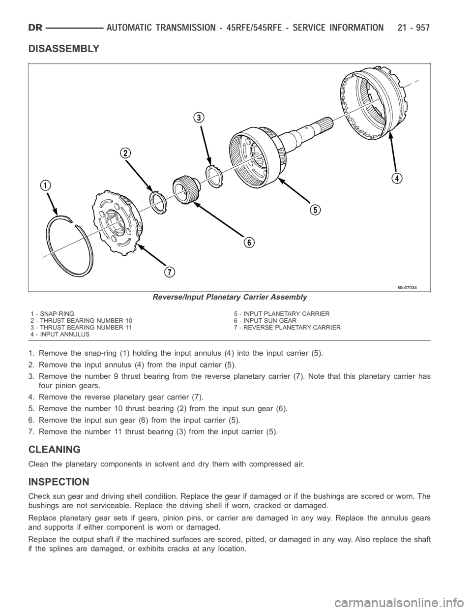
1. Remove the snap-ring (1) holding the input annulus (4) into the input carrier (5).
2. Remove the input annulus (4) from the input carrier (5).
3. Remove the number 9 thrust bearing from the reverse planetary carrier (7). Note that this planetary carrier has
four pinion gears.
4. Remove the reverse planetary gear carrier (7).
5. Remove the number 10 thrust bearing (2) from the input sun gear (6).
6. Remove the input sun gear (6) from the input carrier (5).
7. Remove the number 11 thrust bearing (3) from the input carrier (5).
CLEANING
Clean the planetary components in solvent and dry them with compressed air.
INSPECTION
Check sun gear and driving shell condition. Replace the gear if damaged or if the bushings are scored or worn. The
bushings are not serviceable. Replace the driving shell if worn, cracked or damaged.
Replace planetary gear sets if gears, pinion pins, or carrier are damaged in any way. Replace the annulus gears
and supports if either component is worn or damaged.
Replace the output shaft if the machined surfaces are scored, pitted, or damaged in any way. Also replace the shaft
if the splines are damaged, or exhibits cracks at any location.
Reverse/Input Planetary Carrier Assembly
1 - SNAP-RING 5 - INPUT PLANETARY CARRIER
2 - THRUST BEARING NUMBER 10 6 - INPUT SUN GEAR
3 - THRUST BEARING NUMBER 11 7 - REVERSE PLANETARY CARRIER
4 - INPUT ANNULUS