2006 DODGE RAM SRT-10 oil filter
[x] Cancel search: oil filterPage 1939 of 5267
d. Install fuel line brace bolts-to-intake manifold finger tight for fuellines#2thru#5.
e. Install fuel line brace nut to rear lift bracket stud, finger tight, for fuel line #6.
f. Hand tighten fuel pump to fuel rail line.
g. Torque fuel line nuts at cylinder head to 30 Nꞏm ( 22 ft. lbs.).
h. Torque fuel line nuts at fuel rail to 30 Nꞏm (22 ft. lbs.)
i. Usingabackupwrench,torquefuelpumptofuelraillineto37Nꞏm(27ft.lbs.). At injection pump.
j. Torque fuel pump to fuel rail line to 37 Nꞏm (27 ft. lbs.) at fuel rail.
k. Torque fuel drain banjo bolt at pressure limiting valve and front of fuelfilter housing to 24 Nꞏm (18 ft. lbs.).
l. Torque fuel line brace bolts to 24 Nꞏm (18 ft. lbs.).
m. Torque fuel line brace nut to 24 Nꞏm (18 ft. lbs.).
n. Torque rail bolts to 24 Nꞏm (18 ft. lbs.).
o. Connect fuel pressure sensor.
p. Torque fuel filter mounting bolts to 24 Nꞏm (18 ft. lbs.).
19. Reposition number 6 fuel line shield and torque to 43 Nꞏm (32 ft. lbs.).
20. Install the fuel filter to injection pump low pressure line. Inspect and replace sealing washers if necessary.
Torque banjo bolts to 24 Nꞏm (18 ft. lbs.).
21. Connect fuel return line at back of cylinder head hand tight.
22. Connect fuel return line at filter housing hand tight.
23. Torque banjo connections at cylinder head and fuel filter housing to 24Nꞏm (18 ft. lbs.)
24. Install bracket to rear of filter housing. Torque to 24 Nꞏm (18 ft. lbs.).
25. Using new gaskets, install the intake grid heater and air inlet housing. Torque bolts to 24 Nꞏm (18 ft. lbs.).
26. Install wire harness P-clip and push on clip to air inlet housing.
27. Connect engine oil level indicator tube at fuel filter housing and at air inlet housing.
28. Install the charge air cooler-to-air inlet housing duct assembly. Torque all clamps to 11 Nꞏm (100 in. lbs.).
29. Connect intake grid heater wires.
30. Secure engine harness to front of cylinder head with bolt at four locations.
31. Connect engine coolant temperature sensor connector.
32. Connect radiator upper hose to thermostat housing.
33. Rotate generator into position. Install upper bolt and torque upper and lower bolts.
34. Install wire harness push-on clip below bracket.
35. Install wire harness P-clip to top of bracket.
36. Install fan support and torque to 32 Nꞏm (24 ft. lbs.).
37. Install cooling fan/drive refer to (Refer to 7 - COOLING/ENGINE/RADIATOR FAN - INSTALLATION).
38. Install accessory drive belt (Refer to 7 - COOLING/ACCESSORY DRIVE/DRIVE BELTS - INSTALLATION).
39. Install exhaust manifold/turbocharger assembly, using new gaskets.Start all bolts/spacers by hand. Starting
from the center bolts out, Torque bolts to 43 Nꞏm (32 ft. lbs.), then retorque from the center out again.
40. Install exhaust manifold heat shield to exhaust manifold studs. Install retaining nuts.Torque to 24 Nꞏm (18 ft.
lbs.).
41. Install exhaust bolt retention straps across cylinders 5 & 6.
42. Using a new gasket, connect the turbocharger oil drain tube. Torque to 24Nꞏm(18ft.lbs.).
43. Perform the turbocharger pre-lube procedure. (Refer to 11 - EXHAUST SYSTEM/TURBOCHARGER SYSTEM/
TURBOCHARGER - INSTALLATION)
44. Connect the turbocharger oil supply line. Torque to 24 Nꞏm (18 ft. lbs.).
45. Install air cleaner housing and duct.
46. Connect air inlet temperature/pressure sensor.
47. Raise vehicle on hoist.
Page 1990 of 5267
a. The connecting rod split/face mustface toward the same side as the piston notch feature on the skirt. The
split face will face toward the exhaust side of the engine if properly installed.
11. Install the rod cap and bolts to the connecting rod. Tighten the connecting rod bolts evenly in 3 steps.
Tighten the bolts to 30 Nꞏm (22 ft. lbs.) torque.
Tighten the bolts to 60 Nꞏm (44 ft. lbs.) torque.
Rotate 60° clockwise.
12. The crankshaft must rotate freely. Check for freedom of rotation as thecaps are installed. If the crankshaft does
not rotate freely, check the installation of the rod bearing and the bearingsize.
13. Measure the side clearance between the connecting rod and the crankshaft. DO NOT measure the clearance
between the cap and crankshaft.
14. Install J-jet piston cooling nozzles.
15. Install block stiffener. Torque to 43 Nꞏm (32 ft. lbs.).
16. Install the suction tube and oil pan (Refer to 9 - ENGINE/LUBRICATION/OIL PAN - INSTALLATION).
17. Install the cylinder head onto the engine (Refer to 9 - ENGINE/CYLINDERHEAD - INSTALLATION).
18. Install a new filter and fill the crankcase with new engine oil.Prefill the filter with clean oil.
19. Connect the battery negative cables and start engine.
Page 1997 of 5267
LUBRICATION
DESCRIPTION
A gear driven gerotor type oil pump is mounted behind the front gear cover inthe lower right portion on the engine.
OPERATION
A gerotor style oil pump draws oil from the crankcase through the suction tube and delivers it through the block
where it enters the oil cooler cover and pressure regulator valve. When oilpressure exceeds 517 kPa (75 PSI), the
valve opens exposing the dump port, which routes excess oil back to the oil pump.
At the same time, oil is directed to a cast in passage in the oil cooler cover,leading to the oil cooler element. As the
oil travels through the element plates, it is cooled by engine coolant traveling past the outside of the plates. It is
then routed to the oil filter head and through a full flow oil filter. If a plugged filter is encountered, the filter by-pass
valve opens, allowing unfiltered oil to lubricate the engine. This condition can be avoided by frequent oil and filter
changes, per the maintenance schedules found in the owners manual. The by-pass valve is calibrated to open when
it sees a pressure drop of more than 345 kPa (50 psi) across the oil filter.
The oil filter head then divides the oil between the engine and the turbocharger. The turbocharger receives filtered,
cooled and pressurized oil through a supply line from the filter head. The oil lubricates the turbocharger and returns
to the pan by way of a drain tube connecting the bottom of the turbocharger toa tube in the cylinder block.
Page 2001 of 5267
DIAGNOSIS AND TESTING—ENGINE OIL PRESSURE
1. Remove the 1/8 npt plug from the top of the oil filter housing.
2. Install Oil Pressure Line and Gauge Tool C-3292 with a suitable adapter.
3. Start engine and warm to operating temperature.
4. Record engine oil pressure and compare with engine oil pressure chart.
CAUTION: If engine oil pressure is zero at idle, DO NOT RUN THE ENGINE.
Engine Oil Pressure (MIN)
At Idle 68.9 kPa (10 psi)
At 2500 rpm 206.9 kPa (30 psi)
If minimum engine oil pressure is below these ranges, (Refer to 9 - ENGINE - DIAGNOSIS AND TESTING).
5. Remove oil pressure gauge and install the 1/8 npt plug.
Page 2002 of 5267
OIL
STANDARD PROCEDURE
STANDARD PROCEDURE - ENGINE OIL LEVEL
CAUTION: Do not overfill crankcase with engine
oil, oil foaming and oil pressure loss can result.
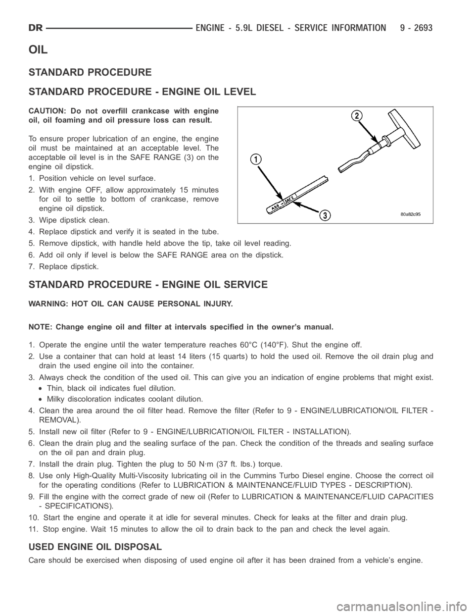
To ensure proper lubrication of an engine, the engine
oil must be maintained at an acceptable level. The
acceptable oil level is in the SAFE RANGE (3) on the
engine oil dipstick.
1. Position vehicle on level surface.
2. With engine OFF, allow approximately 15 minutes
for oil to settle to bottom of crankcase, remove
engine oil dipstick.
3. Wipe dipstick clean.
4. Replace dipstick and verify it is seated in the tube.
5. Remove dipstick, with handle held above the tip, take oil level reading.
6. Add oil only if level is below the SAFE RANGE area on the dipstick.
7. Replace dipstick.
STANDARD PROCEDURE - ENGINE OIL SERVICE
WARNING: HOT OIL CAN CAUSE PERSONAL INJURY.
NOTE: Change engine oil and filter at intervals specified in the owner’s manual.
1. Operate the engine until the water temperature reaches 60°C (140°F). Shut the engine off.
2. Use a container that can hold at least 14 liters (15 quarts) to hold the used oil. Remove the oil drain plug and
drain the used engine oil into the container.
3. Always check the condition of the used oil. This can give you an indication of engine problems that might exist.
Thin, black oil indicates fuel dilution.
Milky discoloration indicates coolant dilution.
4. Clean the area around the oil filter head. Remove the filter (Refer to 9 - ENGINE/LUBRICATION/OIL FILTER -
REMOVAL).
5. Install new oil filter (Refer to 9 - ENGINE/LUBRICATION/OIL FILTER - INSTA L L AT I O N ) .
6. Clean the drain plug and the sealing surface of the pan. Check the condition of the threads and sealing surface
on the oil pan and drain plug.
7. Install the drain plug. Tighten the plug to 50 Nꞏm (37 ft. lbs.) torque.
8. Use only High-Quality Multi-Viscosity lubricating oil in the Cummins Turbo Diesel engine. Choose the correct oil
for the operating conditions (Refer to LUBRICATION & MAINTENANCE/FLUID TYPES - DESCRIPTION).
9. Fill the engine with the correct grade of new oil (Refer to LUBRICATION & MAINTENANCE/FLUID CAPACITIES
- SPECIFICATIONS).
10. Start the engine and operate it at idle for several minutes. Check for leaks at the filter and drain plug.
11. Stop engine. Wait 15 minutes to allow the oil to drain back to the pan and check the level again.
USED ENGINE OIL DISPOSAL
Care should be exercised when disposing of used engine oil after it has beendrained from a vehicle’s engine.
Page 2004 of 5267
FILTER - ENGINE OIL
REMOVAL
1. Clean the area around the oil filter head. Remove the filter from below using a cap-style filter wrench.
2. Clean the gasket surface of the filter head. The filter canister O-Ring seal can stick on the filter head. Make sure
it is removed.
INSTALLATION
1. Fill the oil filter element with clean oil before installation. Use the same type oil that will be used in the engine.
2. Apply a light film of lubricating oil to the sealing surface before installing the filter.
CAUTION: Mechanical over-tightening may distort the threads or damage the filter element seal.
3. Install the filter until it contacts the sealing surface of the oil filter adapter. Tighten filter an additional
1⁄2turn.
Page 2006 of 5267
VALVE - OIL PRESSURE RELIEF
REMOVAL
1. Disconnect the battery negative cables.
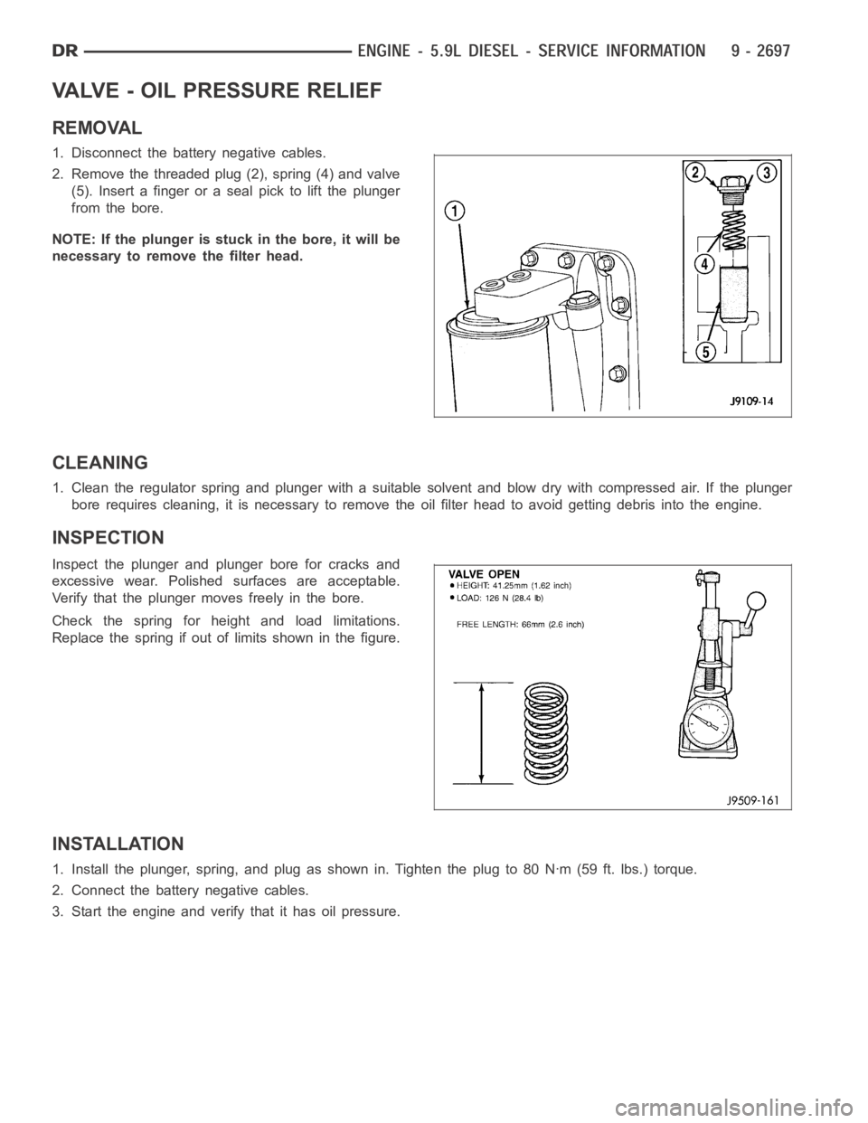
2. Remove the threaded plug (2), spring (4) and valve
(5). Insert a finger or a seal pick to lift the plunger
from the bore.
NOTE: If the plunger is stuck in the bore, it will be
necessary to remove the filter head.
CLEANING
1. Clean the regulator spring and plunger with a suitable solvent and blow dry with compressed air. If the plunger
bore requires cleaning, it is necessaryto remove the oil filter head to avoid getting debris into the engine.
INSPECTION
Inspect the plunger and plunger bore for cracks and
excessive wear. Polished surfaces are acceptable.
Verify that the plunger moves freely in the bore.
Check the spring for height and load limitations.
Replace the spring if out of limits shown in the figure.
INSTALLATION
1. Install the plunger, spring, and plug as shown in. Tighten the plug to 80 Nꞏm (59 ft. lbs.) torque.
2. Connect the battery negative cables.
3. Start the engine and verify that it has oil pressure.
Page 2011 of 5267
MANIFOLD - INTAKE
REMOVAL
1. Disconnect the battery negative cables.
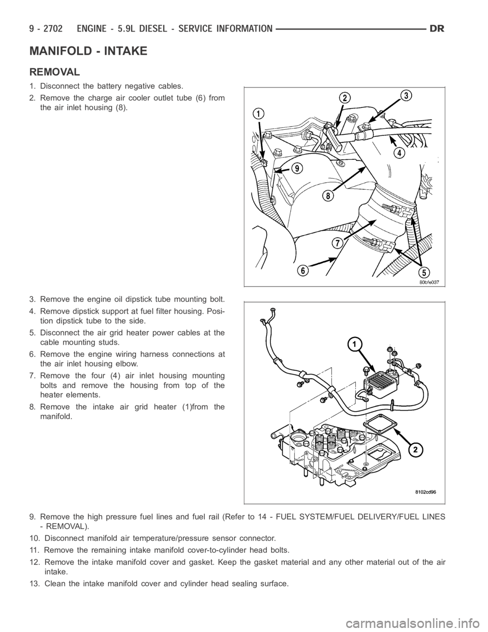
2. Remove the charge air cooler outlet tube (6) from
the air inlet housing (8).
3. Remove the engine oil dipstick tube mounting bolt.
4. Remove dipstick support at fuel filter housing. Posi-
tion dipstick tube to the side.
5. Disconnect the air grid heater power cables at the
cable mounting studs.
6. Remove the engine wiring harness connections at
the air inlet housing elbow.
7. Remove the four (4) air inlet housing mounting
bolts and remove the housing from top of the
heater elements.
8. Remove the intake air grid heater (1)from the
manifold.
9. Remove the high pressure fuel lines and fuel rail (Refer to 14 - FUEL SYSTEM/FUEL DELIVERY/FUEL LINES
- REMOVAL).
10. Disconnect manifold air temperature/pressure sensor connector.
11. Remove the remaining intake manifold cover-to-cylinder head bolts.
12. Remove the intake manifold cover and gasket. Keep the gasket material and any other material out of the air
intake.
13. Clean the intake manifold cover and cylinder head sealing surface.