2006 DODGE RAM SRT-10 oil filter
[x] Cancel search: oil filterPage 2163 of 5267
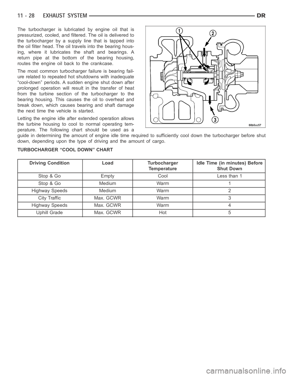
The turbocharger is lubricated by engine oil that is
pressurized, cooled, and filtered. The oil is delivered to
the turbocharger by a supply line that is tapped into
the oil filter head. The oil travels into the bearing hous-
ing, where it lubricates the shaft and bearings. A
return pipe at the bottom of the bearing housing,
routes the engine oil back to the crankcase.
The most common turbocharger failure is bearing fail-
ure related to repeated hot shutdowns with inadequate
“cool-down” periods. A sudden engine shut down after
prolonged operation will result in the transfer of heat
from the turbine section of the turbocharger to the
bearing housing. This causes the oil to overheat and
break down, which causes bearing and shaft damage
thenexttimethevehicleisstarted.
Letting the engine idle after extended operation allows
the turbine housing to cool to normal operating tem-
perature. The following chart should be used as a
guide in determining the amount of engine idle time required to sufficiently cool down the turbocharger before shut
down, depending upon the type of driving and the amount of cargo.
TURBOCHARGER “COOL DOWN” CHART
Driving Condition Load Turbocharger
TemperatureIdle Time (in minutes) Before
Shut Down
Stop & Go Empty Cool Less than 1
Stop & Go Medium Warm 1
Highway Speeds Medium Warm 2
City Traffic Max. GCWR Warm 3
Highway Speeds Max. GCWR Warm 4
Uphill Grade Max. GCWR Hot 5
Page 2343 of 5267
Fuel enters the system from the electric fuel transfer (lift) pump, which is located inside of the fuel tank and attached
to the fuel tank module (the fuel transfer pump is no longer attached to the engine). Fuel is forced through the fuel
filter element and then enters the Fuel Pump/Gear Pump, which is attached to the rear of the fuel injection pump.
The Fuel Pump/Gear Pump is a low-pressure pump and produce pressures ranging from 551.5 kpa (80 psi) to 1241
kpa (180) psi. Fuel then enters the fuel injection pump. Low pressure fuel is then supplied to the FCA (Fuel Control
Actuator).
The FCA is an electronically controlled solenoid valve. The ECM controls the amount of fuel that enters the high-
pressure pumping chambers by opening and closing the FCA based on a demanded fuel pressure. The FPS (Fuel
Pressure Sensor) on the fuel rail monitors the actual fuel pressure and provides it as an input to the ECM. When
the actuator is opened, the maximum amount of fuel is being supplied to the fuel injection pump. Any fuel that does
not enter the injection pump is directed to the overflow valve. The overflow valve regulates how much excess fuel
is used for lubrication of the pump and how much is returned to the tank through the drain manifold.
Fuel entering the injection pump is pressurized to between 300-1600 bar (4351-23,206 psi) by three radial pumping
chambers. The pressurized fuel is then supplied to the fuel rail.
STANDARD PROCEDURE
WATER DRAINING AT FUEL FILTER
Refer to Fuel Filter/Water Separatorremoval/installation for procedures.
CLEANING FUEL SYSTEM PARTS
CAUTION: Cleanliness cannot be overemphasized when handling or replacingdieselfuelsystemcompo-
nents. This especially includes the fuel injectors, high-pressure fuel lines and fuel injection pump. Very tight
tolerances are used with these parts. Dirt contamination could cause rapid part wear and possible plugging
of fuel injector nozzle tip holes. This in turn could lead to possible engine misfire. Always wash/clean any
fuel system component thoroughly before disassembly and then air dry. Capor cover any open part after
disassembly. Before assembly, examine each part for dirt, grease or othercontaminants and clean if nec-
essary. When installing new parts, lubricate them with clean engine oil orclean diesel fuel only.
FUEL SYSTEM PRIMING
A certain amount of air becomes trappedin the fuel system when fuel system components on the supply and/or
high-pressure side are serviced or replaced. Fuel system priming is accomplished using the electric fuel transfer (lift)
pump.
Servicing or replacing fuel system components will not require fuel systempriming.
The fuel transfer (lift) pump is self-priming: When the key is first turnedon (without cranking engine), the pump
operates for approximately 1 to 2 second and then shuts off (Note: When ambient temperatures are cold enough to
cause the intake air heaters to operate, the fuel lift pump will operate during the entire intake air pre-heat cycle).
The pump will also operate for up to 25 seconds after the starter is quickly engaged, and then disengaged without
allowing the engine to start. The pump shuts off immediately if the key is onand the engine stops running.
1. Turn key to CRANK position and quickly release key to ON position before engine starts. This will operate fuel
transfer pump for approximately 25 seconds.
2. Crank engine. If the engine does not start after 25 seconds, turn key to OFF position, and leave it off for at least
5 seconds. Repeat previous step until engine starts.
3. Fuel system priming is now completed.
4. Attempt to start engine. If engine will not start, proceed to following steps.When engine does start, it may run
erratically and be noisy for a few minutes. This is a normal condition.
CAUTION: Do not engage the starter motor for more than 30 seconds at a time. Allow two minutes between
cranking intervals.
5. Perform previous fuel priming procedure steps using fuel transfer pump. Be sure fuel is present at fuel tank.
6. Crank the engine for 30 seconds at a time to allow fuel system to prime.
Page 2350 of 5267
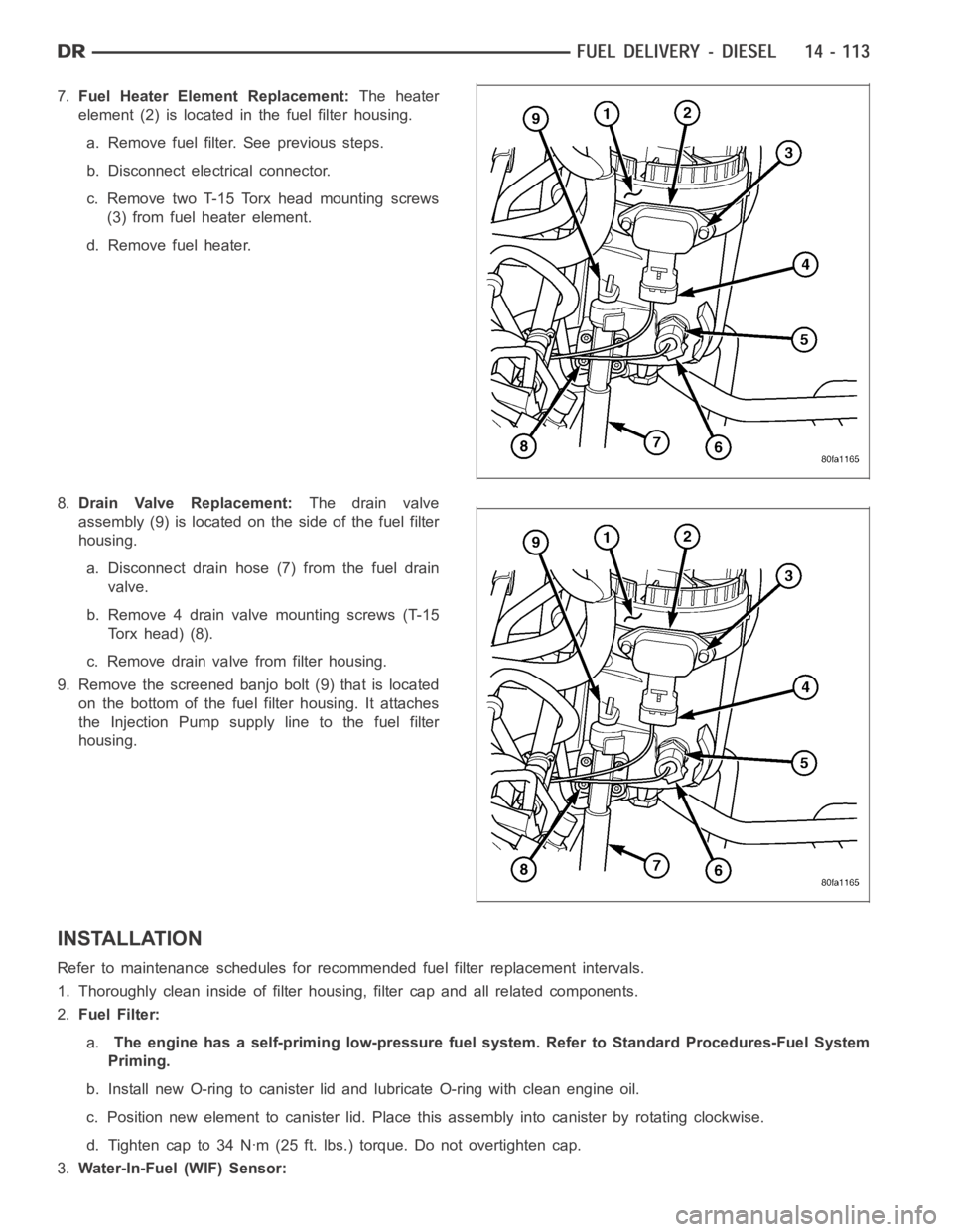
7.Fuel Heater Element Replacement:The heater
element (2) is located in the fuel filter housing.
a. Remove fuel filter. See previous steps.
b. Disconnect electrical connector.
c. Remove two T-15 Torx head mounting screws
(3) from fuel heater element.
d. Remove fuel heater.
8.Drain Valve Replacement:The drain valve
assembly (9) is located on the side of the fuel filter
housing.
a. Disconnect drain hose (7) from the fuel drain
valve.
b. Remove 4 drain valve mounting screws (T-15
Torx head) (8).
c. Remove drain valve from filter housing.
9. Remove the screened banjo bolt (9) that is located
on the bottom of the fuel filter housing. It attaches
the Injection Pump supply line to the fuel filter
housing.
INSTALLATION
Refer to maintenance schedules for recommended fuel filter replacement intervals.
1. Thoroughly clean inside of filter housing, filter cap and all related components.
2.Fuel Filter:
a.The engine has a self-priming low-pressure fuel system. Refer to StandardProcedures-Fuel System
Priming.
b. Install new O-ring to canister lid and lubricate O-ring with clean engine oil.
c. Position new element to canister lid. Place this assembly into canisterby rotating clockwise.
d. Tighten cap to 34 Nꞏm (25 ft. lbs.) torque. Do not overtighten cap.
3.Water-In-Fuel (WIF) Sensor:
Page 2351 of 5267
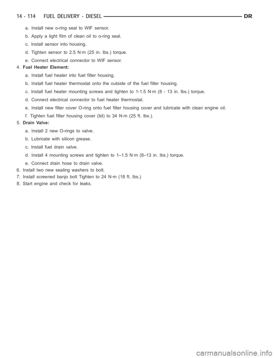
a. Install new o-ring seal to WIF sensor.
b. Apply a light film of clean oil to o-ring seal.
c. Install sensor into housing.
d. Tighten sensor to 2.5 Nꞏm (25 in. lbs.) torque.
e. Connect electrical connector to WIF sensor.
4.Fuel Heater Element:
a. Install fuel heater into fuel filter housing.
b. Install fuel heater thermostat onto the outside of the fuel filter housing.
c. Install fuel heater mounting screws and tighten to 1-1.5 Nꞏm (8 - 13 in. lbs.) torque.
d. Connect electrical connector to fuel heater thermostat.
e. Install new filter cover O-ring onto fuel filter housing cover and lubricate with clean engine oil.
f. Tighten fuel filter housing cover (lid) to 34 Nꞏm (25 ft. lbs.).
5.Drain Valve:
a. Install 2 new O-rings to valve.
b. Lubricate with silicon grease.
c. Installfueldrainvalve.
d. Install 4 mounting screws and tighten to 1–1.5 Nꞏm (8–13 in. lbs.) torque.
e. Connect drain hose to drain valve.
6. Install two new sealing washers to bolt.
7. Install screened banjo bolt Tighten to 24 Nꞏm (18 ft. lbs.)
8. Start engine and check for leaks.
Page 2354 of 5267
PUMP - FUEL INJECTION
DESCRIPTION
A Robert Bosch high-pressure fuel injection pump is used. The pump is attached to the back of the timing gear
housing at the left /front side of the engine.
OPERATION
The fuel injection pump supplies high pressure to the fuel rail independent of engine speed. This high pressure is
then accumulated in the fuel rail. High pressure fuel is constantly supplied to the injectors by the fuel rail. The
Engine Control Module (ECM) controls the fueling and timing of the engine by actuating the injectors.
Fuel enters the system from the electric fuel transfer (lift) pump, which is located in the fuel tank. Fuel is forced
through the fuel filter element and then enters the Fuel Pump/Gear Pump, which is attached to the rear of the fuel
injection pump. The Fuel Pump/Gear Pump is a low-pressure pump and producepressures ranging from 551.5 kpa
(80 psi) to 1241 kpa (180) psi. Fuel then enters the fuel injection pump. Lowpressure fuel is then supplied to the
FCA (Fuel Control Actuator).
The FCA is an electronically controlled solenoid valve. The ECM controls the amount of fuel that enters the high-
pressure pumping chambers by opening and closing the FCA based on a demanded fuel pressure. The FPS (Fuel
Pressure Sensor) on the fuel rail provides the actual fuel pressure. When the actuator is opened, the maximum
amount of fuel is being supplied to the fuel injection pump. Any fuel that does not enter the injection pump is
directed to the cascade overflow valve. The cascade overflow valve regulates how much excess fuel is used for
lubrication of the pump and how much is returned to the tank through the drain manifold.
Fuel entering the injection pump is pressurized to between 300-1600 bar (4351-23206 psi) by three radial pumping
chambers. The pressurized fuel is then supplied to the fuel rail.
DIAGNOSIS AND TESTING
FUEL INJECTION PUMP TIMING
With the Bosch injection pump, there are no mechanical adjustments neededor necessary to accomplish fuel injec-
tion timing. All timing and fuel adjustments are electrically made by the engine mounted Engine Control Module
(ECM).
REMOVAL
CAUTION: Cleanliness cannot be overemphasized when handling or replacingdieselfuelsystemcompo-
nents. This especially includes the fuel injectors, high-pressure fuel lines and fuel injection pump. Very tight
tolerances are used with these parts. Dirt contamination could cause rapid part wear and possible plugging
of fuel injector nozzle tip holes. This in turn could lead to possible engine misfire. Always wash/clean any
fuel system component thoroughly before disassembly and then air dry. Capor cover any open part after
disassembly. Before assembly, examine each part for dirt, grease or othercontaminants and clean if nec-
essary. When installing new parts, lubricate them with clean engine oil orclean diesel fuel only.
Page 2398 of 5267
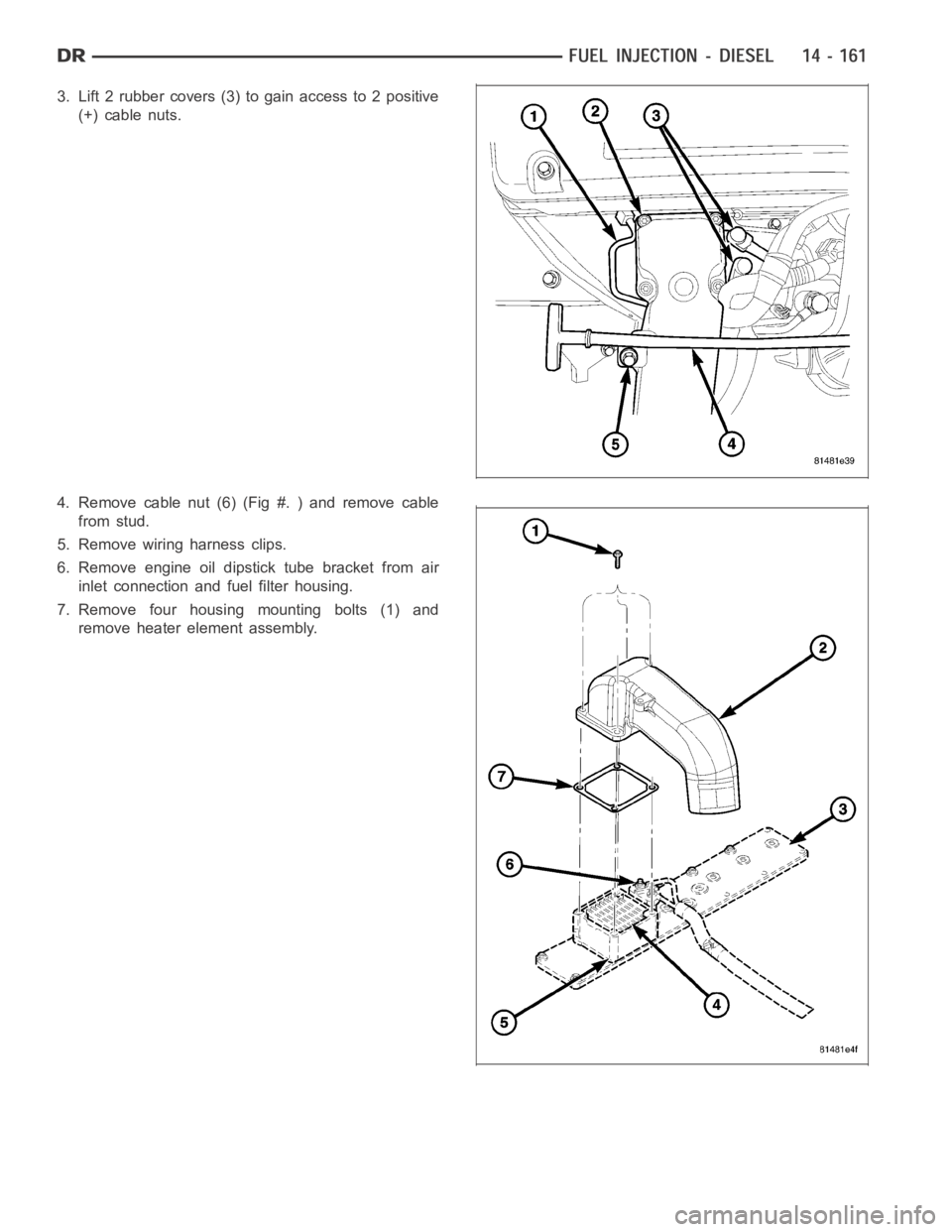
3. Lift 2 rubber covers (3) to gain access to 2 positive
(+) cable nuts.
4. Remove cable nut (6) (Fig #. ) and remove cable
from stud.
5. Remove wiring harness clips.
6. Remove engine oil dipstick tube bracket from air
inlet connection and fuel filter housing.
7. Remove four housing mounting bolts (1) and
remove heater element assembly.
Page 2816 of 5267
When Monitored:
Continuously while driving in a forward gear.
Set Condition:
The PCM continuously monitors Actual Line Pressure and compares it to DesiredLinePressure.IftheActual
Line Pressure is more than 10 psi below Desired Line Pressure, this DTC willset.
Possible Causes
CHECK FOR RELATED DTC’S
LOW FLUID LEVEL
(F856) 5-VOLT SUPPLY CIRCUIT OPEN
(F856) 5-VOLT SUPPLY CIRCUIT SHORT TO GROUND
(F856) 5-VOLT SUPPLY CIRCUIT SHORT TO VOLTAGE
(T118) PRESSURE CONTROL SOLENOID CONTROL CIRCUIT SHORT TO ANOTHER CIRCUIT
INTERNAL TRANSMISSION
LINE PRESSURE SENSOR
CRACKED, PLUGGED, OR MIS-INSTALLED PRIMARY OIL FILTER
STUCK OR STICKING MAIN REGULATOR VALVE
POWERTRAIN CONTROL MODULE
Always perform the 42RLE Pre-Diagnostic Troubleshooting procedure before proceeding. (Refer to 21 -
TRANSMISSION/TRANSAXLE/AUTOMATIC - 42RLE - STANDARD PROCEDURE)
Theory of Operation
Line pressure is measured by the Line Pressure Sensor (LPS) and regulationis achieved by changing the duty
cycle of the Pressure Control Solenoid (PCS) controlled by the Transmission Control System. (5% duty cycle =
solenoid off = Max line pressure, 62%duty cycle = solenoid on = Min line pressure). The Transmission Control
System calculates the desired line pressure based on inputs from both the engine and transmission.
The Transmission Control System calculates torque input to the transmission and uses it as the primary input to the
desired line pressure calculation. This is called Torque Based Line Pressure. In addition, the line pressure is set to
a preset level 827 or 931 kPa (120 or 135 psi) during shifts and in Park and Neutral to ensure consistent shift
quality. The desired line pressure is continuously being compared to the actual line pressure. If the actual line pres-
sure is consistently lower than the target while driving, the line pressure low DTC P0868 will set.
Diagnostic Test
1.CHECKFORRELATEDDTCS
With the scan tool, check for other transmission DTCs
Is the DTC P0932 present also?
Ye s>>
Refer to the Transmission category and perform the appropriate symptom.
No>>
Go To 2
Page 2818 of 5267
5.CHECK FOR A PLUGGED TRANSMISSION OIL FILTER
Turn the ignition off to the lock position.
Remove and inspect the Transmission Oil Pan for excessive debris per the Service Information.
Remove and inspect the Transmission Oil Filter per the Service Information.
Does the Oil Pan contain excessive debris and/or is the Transmission Oil Filter plugged?
Ye s>>
Repair as necessary. If the Transmission Oil Filter is plugged or there is excessive debris, refer to the
Service Information for the proper Hydraulic repair procedure.
Perform 42RLE TRANSMISSION VERIFICATION TEST - VER 1. (Refer to 21 - TRANSMISSION/
TRANSAXLE/AUTOMATIC - 42RLE - STANDARD PROCEDURE)
No>>
Repair internal transmission and inspect the Transmission Oil Pump per the Service Information and
replace if necessary.
Perform 42RLE TRANSMISSION VERIFICATION TEST - VER 1. (Refer to 21 - TRANSMISSION/
TRANSAXLE/AUTOMATIC - 42RLE - STANDARD PROCEDURE)
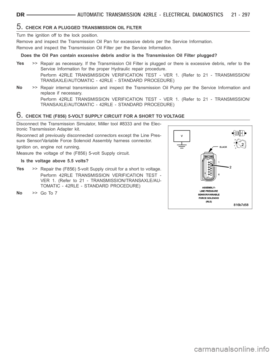
6.CHECK THE (F856) 5-VOLT SUPPLY CIRCUIT FOR A SHORT TO VOLTAGE
Disconnect the Transmission Simulator, Miller tool #8333 and the Elec-
tronic Transmission Adapter kit.
Reconnect all previously disconnected connectors except the Line Pres-
sure Sensor/Variable Force Solenoid Assembly harness connector.
Ignition on, engine not running.
Measure the voltage of the (F856) 5-volt Supply circuit.
Is the voltage above 5.5 volts?
Ye s>>
Repair the (F856) 5-volt Supply circuit for a short to voltage.
Perform 42RLE TRANSMISSION VERIFICATION TEST -
VER 1. (Refer to 21 - TRANSMISSION/TRANSAXLE/AU-
TOMATIC - 42RLE - STANDARD PROCEDURE)
No>>
Go To 7