2006 DODGE RAM SRT-10 oil filter
[x] Cancel search: oil filterPage 2850 of 5267
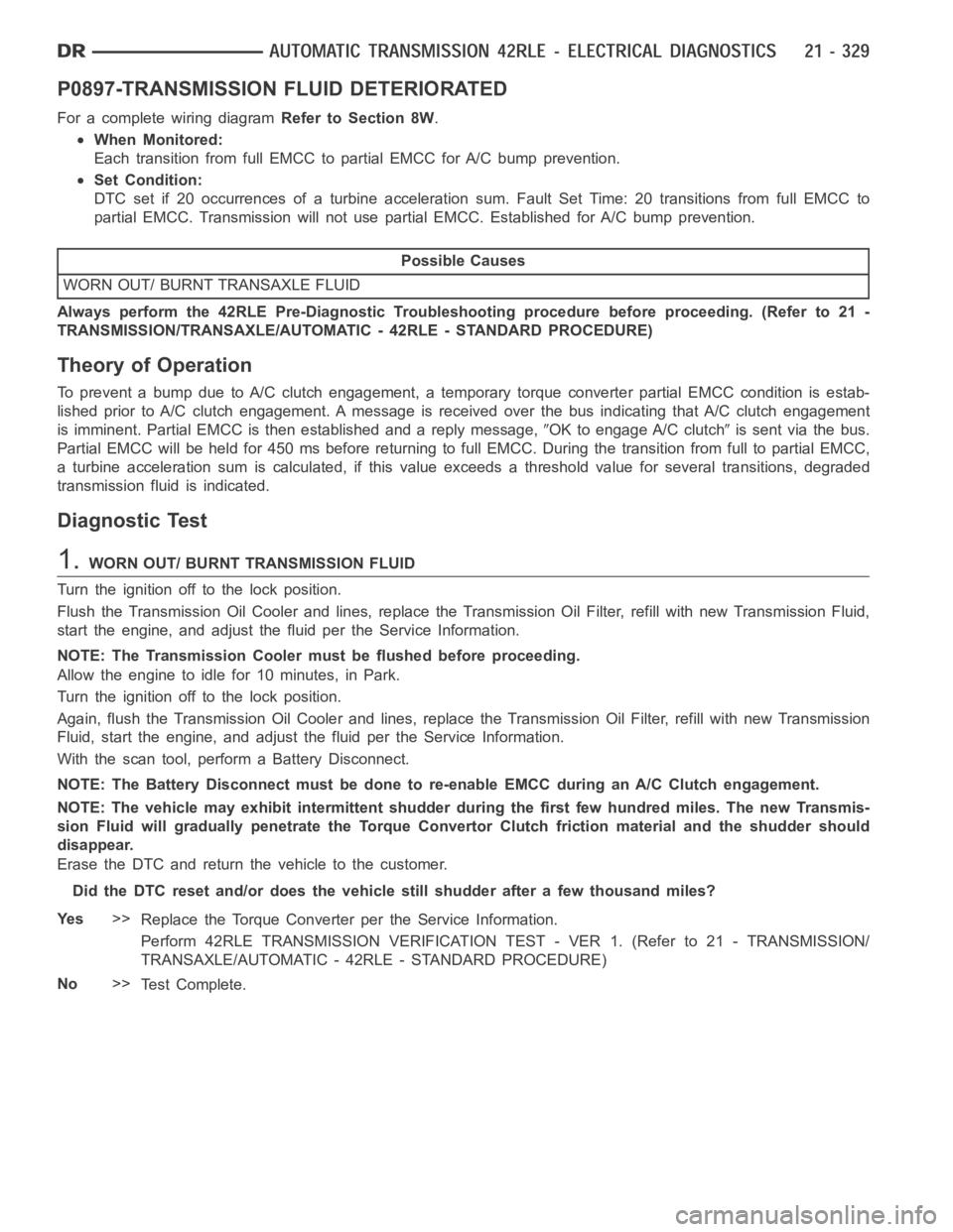
P0897-TRANSMISSION FLUID DETERIORATED
For a complete wiring diagramRefer to Section 8W.
When Monitored:
Each transition from full EMCC to partial EMCC for A/C bump prevention.
Set Condition:
DTC set if 20 occurrences of a turbine acceleration sum. Fault Set Time: 20 transitions from full EMCC to
partial EMCC. Transmission will not use partial EMCC. Established for A/Cbump prevention.
Possible Causes
WORN OUT/ BURNT TRANSAXLE FLUID
Always perform the 42RLE Pre-Diagnostic Troubleshooting procedure before proceeding. (Refer to 21 -
TRANSMISSION/TRANSAXLE/AUTOMATIC - 42RLE - STANDARD PROCEDURE)
Theory of Operation
To prevent a bump due to A/C clutch engagement, a temporary torque converter partial EMCC condition is estab-
lished prior to A/C clutch engagement. A message is received over the bus indicating that A/C clutch engagement
is imminent. Partial EMCC is then established and a reply message,
OK to engage A/C clutchis sent via the bus.
Partial EMCC will be held for 450 ms before returning to full EMCC. During the transition from full to partial EMCC,
a turbine acceleration sum is calculated, if this value exceeds a threshold value for several transitions, degraded
transmission fluid is indicated.
Diagnostic Test
1.WORN OUT/ BURNT TRANSMISSION FLUID
Turn the ignition off to the lock position.
Flush the Transmission Oil Cooler and lines, replace the Transmission OilFilter, refill with new Transmission Fluid,
start the engine, and adjust the fluid per the Service Information.
NOTE: The Transmission Cooler must be flushed before proceeding.
Allow the engine to idle for 10 minutes, in Park.
Turn the ignition off to the lock position.
Again, flush the Transmission Oil Cooler and lines, replace the Transmission Oil Filter, refill with new Transmission
Fluid, start the engine, and adjust the fluid per the Service Information.
With the scan tool, perform a Battery Disconnect.
NOTE: The Battery Disconnect must be done to re-enable EMCC during an A/C Clutch engagement.
NOTE: The vehicle may exhibit intermittent shudder during the first few hundred miles. The new Transmis-
sion Fluid will gradually penetrate the Torque Convertor Clutch frictionmaterial and the shudder should
disappear.
Erase the DTC and return the vehicle to the customer.
Did the DTC reset and/or does the vehicle still shudder after a few thousandmiles?
Ye s>>
Replace the Torque Converter per the Service Information.
Perform 42RLE TRANSMISSION VERIFICATION TEST - VER 1. (Refer to 21 - TRANSMISSION/
TRANSAXLE/AUTOMATIC - 42RLE - STANDARD PROCEDURE)
No>>
Te s t C o m p l e t e .
Page 2864 of 5267
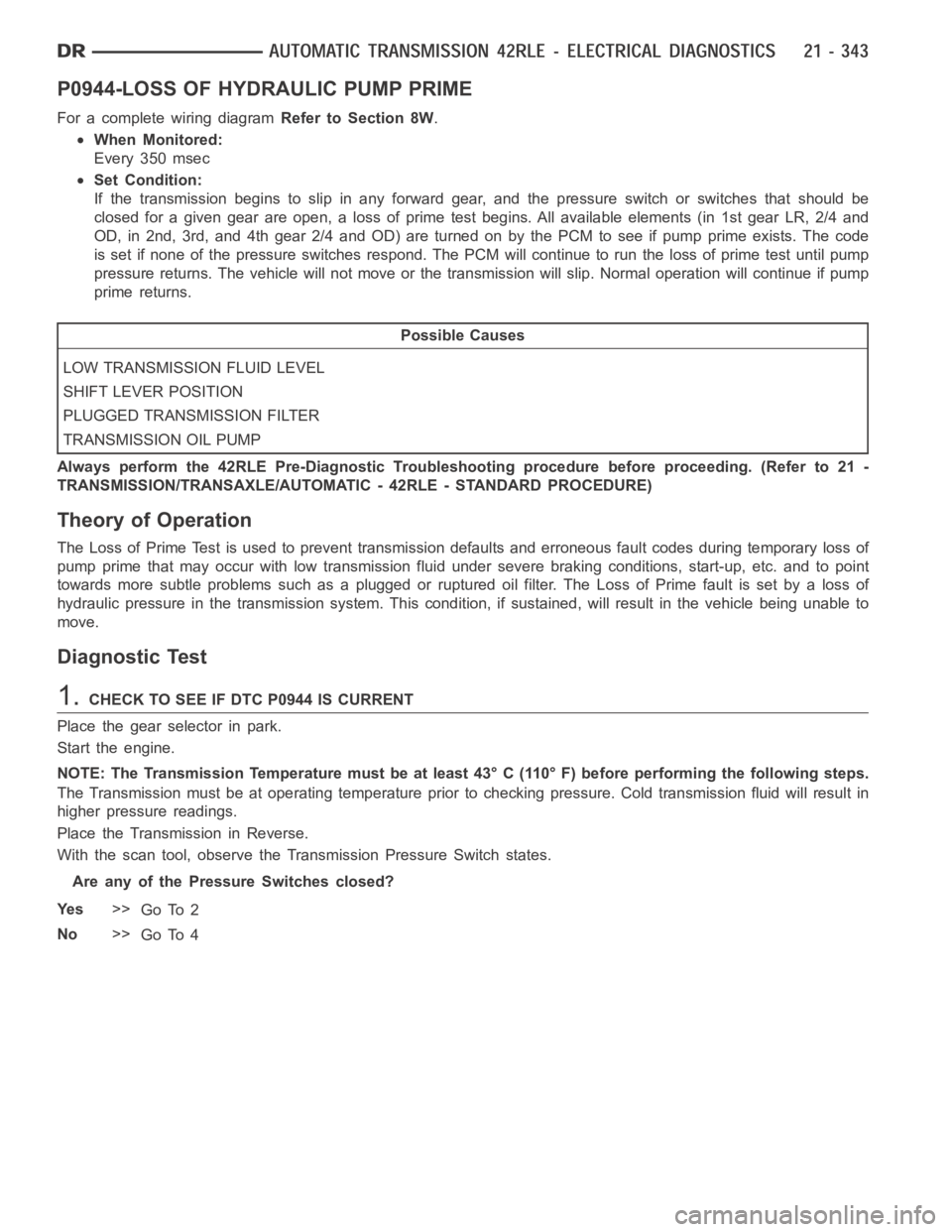
P0944-LOSS OF HYDRAULIC PUMP PRIME
For a complete wiring diagramRefer to Section 8W.
When Monitored:
Every 350 msec
Set Condition:
If the transmission begins to slip in any forward gear, and the pressure switch or switches that should be
closed for a given gear are open, a loss of prime test begins. All available elements (in 1st gear LR, 2/4 and
OD, in 2nd, 3rd, and 4th gear 2/4 and OD) are turned on by the PCM to see if pump prime exists. The code
is set if none of the pressure switches respond. The PCM will continue to runthe loss of prime test until pump
pressure returns. The vehicle will not move or the transmission will slip.Normal operation will continue if pump
prime returns.
Possible Causes
LOW TRANSMISSION FLUID LEVEL
SHIFT LEVER POSITION
PLUGGED TRANSMISSION FILTER
TRANSMISSION OIL PUMP
Always perform the 42RLE Pre-Diagnostic Troubleshooting procedure before proceeding. (Refer to 21 -
TRANSMISSION/TRANSAXLE/AUTOMATIC - 42RLE - STANDARD PROCEDURE)
Theory of Operation
The Loss of Prime Test is used to prevent transmission defaults and erroneous fault codes during temporary loss of
pump prime that may occur with low transmission fluid under severe brakingconditions, start-up, etc. and to point
towards more subtle problems such as a plugged or ruptured oil filter. The Loss of Prime fault is set by a loss of
hydraulic pressure in the transmission system. This condition, if sustained, will result in the vehicle being unable to
move.
Diagnostic Test
1.CHECK TO SEE IF DTC P0944 IS CURRENT
Place the gear selector in park.
Start the engine.
NOTE: The Transmission Temperature must be at least 43° C (110° F) before performing the following steps.
The Transmission must be at operating temperature prior to checking pressure. Cold transmission fluid will result in
higher pressure readings.
Place the Transmission in Reverse.
With the scan tool, observe the Transmission Pressure Switch states.
Are any of the Pressure Switches closed?
Ye s>>
Go To 2
No>>
Go To 4
Page 2865 of 5267
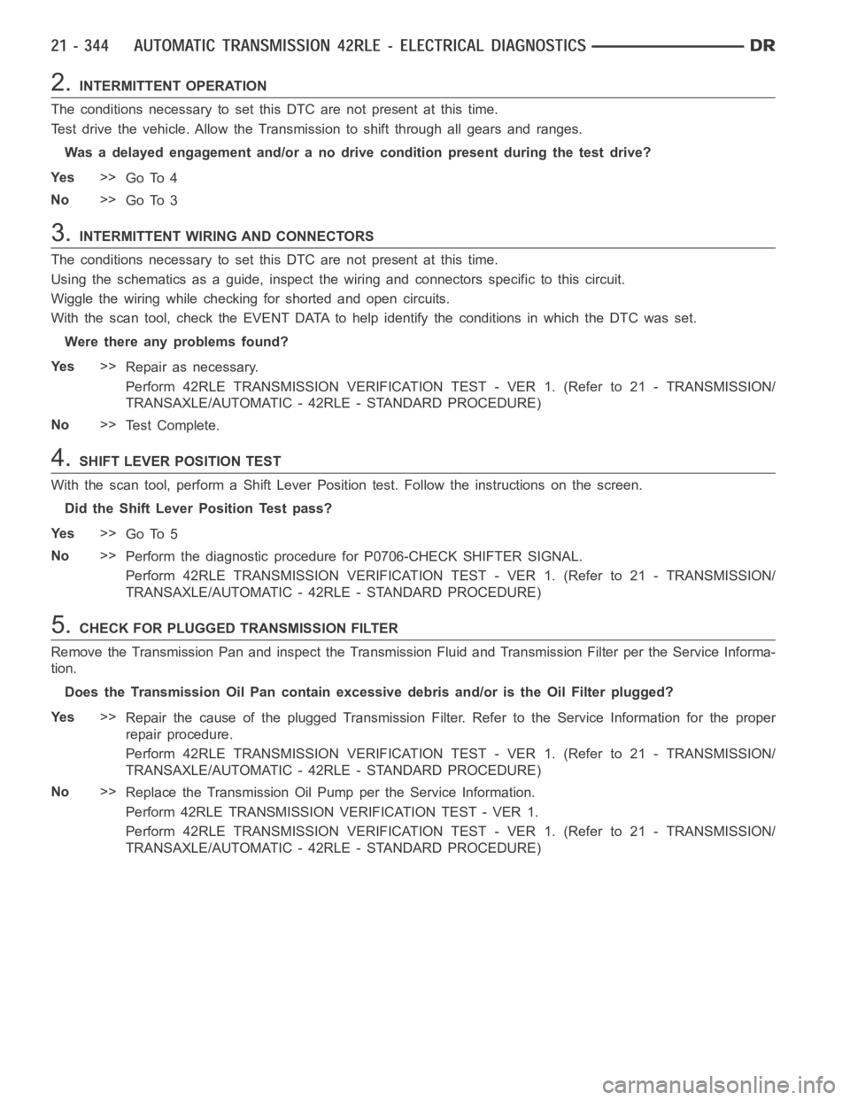
2.INTERMITTENT OPERATION
The conditions necessary to set this DTC are not present at this time.
Test drive the vehicle. Allow the Transmission to shift through all gears and ranges.
Was a delayed engagement and/or a no drive condition present during the testdrive?
Ye s>>
Go To 4
No>>
Go To 3
3.INTERMITTENT WIRING AND CONNECTORS
The conditions necessary to set this DTC are not present at this time.
Using the schematics as a guide, inspect the wiring and connectors specifictothiscircuit.
Wiggle the wiring while checking for shorted and open circuits.
With the scan tool, check the EVENT DATAto help identify the conditions in which the DTC was set.
Were there any problems found?
Ye s>>
Repair as necessary.
Perform 42RLE TRANSMISSION VERIFICATION TEST - VER 1. (Refer to 21 - TRANSMISSION/
TRANSAXLE/AUTOMATIC - 42RLE - STANDARD PROCEDURE)
No>>
Te s t C o m p l e t e .
4.SHIFT LEVER POSITION TEST
With the scan tool, perform a Shift Lever Position test. Follow the instructions on the screen.
Did the Shift Lever Position Test pass?
Ye s>>
Go To 5
No>>
Perform the diagnostic procedure for P0706-CHECK SHIFTER SIGNAL.
Perform 42RLE TRANSMISSION VERIFICATION TEST - VER 1. (Refer to 21 - TRANSMISSION/
TRANSAXLE/AUTOMATIC - 42RLE - STANDARD PROCEDURE)
5.CHECK FOR PLUGGED TRANSMISSION FILTER
Remove the Transmission Pan and inspect the Transmission Fluid and Transmission Filter per the Service Informa-
tion.
Does the Transmission Oil Pan contain excessive debris and/or is the Oil Filter plugged?
Ye s>>
Repair the cause of the plugged Transmission Filter. Refer to the Service Information for the proper
repair procedure.
Perform 42RLE TRANSMISSION VERIFICATION TEST - VER 1. (Refer to 21 - TRANSMISSION/
TRANSAXLE/AUTOMATIC - 42RLE - STANDARD PROCEDURE)
No>>
Replace the Transmission Oil Pump per the Service Information.
Perform 42RLE TRANSMISSION VERIFICATION TEST - VER 1.
Perform 42RLE TRANSMISSION VERIFICATION TEST - VER 1. (Refer to 21 - TRANSMISSION/
TRANSAXLE/AUTOMATIC - 42RLE - STANDARD PROCEDURE)
Page 2910 of 5267
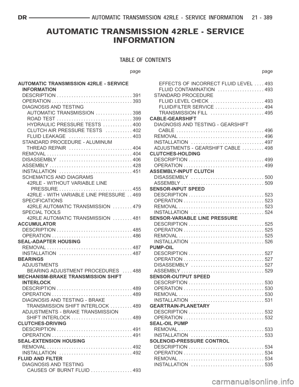
page page
AUTOMATIC TRANSMISSION 42RLE - SERVICE
INFORMATION
DESCRIPTION ............................... 391
OPERATION ................................. 393
DIAGNOSIS AND TESTING
AUTOMATIC TRANSMISSION ............... 398
ROAD TEST ............................... 399
HYDRAULIC PRESSURE TESTS............ 400
CLUTCH AIR PRESSURE TESTS........... 402
FLUID LEAKAGE.......................... 403
STANDARD PROCEDURE - ALUMINUM
THREAD REPAIR .......................... 404
REMOVAL ................................... 404
DISASSEMBLY .............................. 406
ASSEMBLY .................................. 428
INSTALLATION .............................. 451
SCHEMATICS AND DIAGRAMS
42RLE - WITHOUT VARIABLE LINE
PRESSURE............................... 455
42RLE - WITH VARIABLE LINE PRESSURE . . 469
SPECIFICATIONS
42RLE AUTOMATIC TRANSMISSION ........ 479
SPECIAL TOOLS
42RLE AUTOMATIC TRANSMISSION ........ 481
ACCUMULATOR
DESCRIPTION ............................... 485
OPERATION ................................. 486
SEAL-ADAPTER HOUSING
REMOVAL ................................... 487
INSTALLATION .............................. 487
BEARINGS
ADJUSTMENTS
BEARING ADJUSTMENT PROCEDURES.... 488
MECHANISM-BRAKE TRANSMISSION SHIFT
INTERLOCK
DESCRIPTION ............................... 489
OPERATION ................................. 489
DIAGNOSIS AND TESTING - BRAKE
TRANSMISSION SHIFT INTERLOCK ......... 489
ADJUSTMENTS - BRAKE TRANSMISSION
SHIFT INTERLOCK ......................... 489
CLUTCHES-DRIVING
DESCRIPTION ............................... 491
OPERATION ................................. 491
SEAL-EXTENSION HOUSING
REMOVAL ................................... 492
INSTALLATION .............................. 492
FLUID AND FILTER
DIAGNOSIS AND TESTING
CAUSES OF BURNT FLUID ................. 493EFFECTS OF INCORRECT FLUID LEVEL . . . . 493
FLUID CONTAMINATION ................... 493
STANDARD PROCEDURE
FLUID LEVEL CHECK...................... 493
FLUID/FILTER SERVICE .................... 494
TRANSMISSION FILL ...................... 495
CABLE-GEARSHIFT
DIAGNOSIS AND TESTING - GEARSHIFT
CABLE .................................... 496
REMOVAL ................................... 496
INSTALLATION .............................. 497
ADJUSTMENTS - GEARSHIFT CABLE ......... 498
CLUTCHES-HOLDING
DESCRIPTION ............................... 499
OPERATION ................................. 499
ASSEMBLY-INPUT CLUTCH
DISASSEMBLY .............................. 500
ASSEMBLY .................................. 509
SENSOR-INPUT SPEED
DESCRIPTION ............................... 523
OPERATION ................................. 523
REMOVAL ................................... 523
INSTALLATION .............................. 524
SENSOR-VARIABLE LINE PRESSURE
DESCRIPTION ............................... 525
OPERATION ................................. 525
REMOVAL ................................... 525
INSTALLATION .............................. 526
PUMP-OIL
DESCRIPTION ............................... 527
OPERATION ................................. 527
DISASSEMBLY .............................. 527
ASSEMBLY .................................. 529
SENSOR-OUTPUT SPEED
DESCRIPTION ............................... 530
OPERATION ................................. 530
REMOVAL ................................... 530
INSTALLATION .............................. 531
GEARTRAIN-PLANETARY
DESCRIPTION ............................... 532
OPERATION ................................. 532
SEAL-OIL PUMP
REMOVAL ................................... 533
INSTALLATION .............................. 533
SOLENOID-PRESSURE CONTROL
DESCRIPTION ............................... 534
OPERATION ................................. 534
REMOVAL ................................... 534
INSTALLATION .............................. 535
Page 2933 of 5267
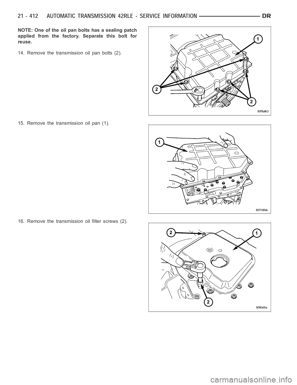
NOTE: One of the oil pan bolts has a sealing patch
applied from the factory. Separate this bolt for
reuse.
14. Remove the transmission oil pan bolts (2).
15. Removethetransmissionoilpan(1).
16. Remove the transmission oil filter screws (2).
Page 2934 of 5267
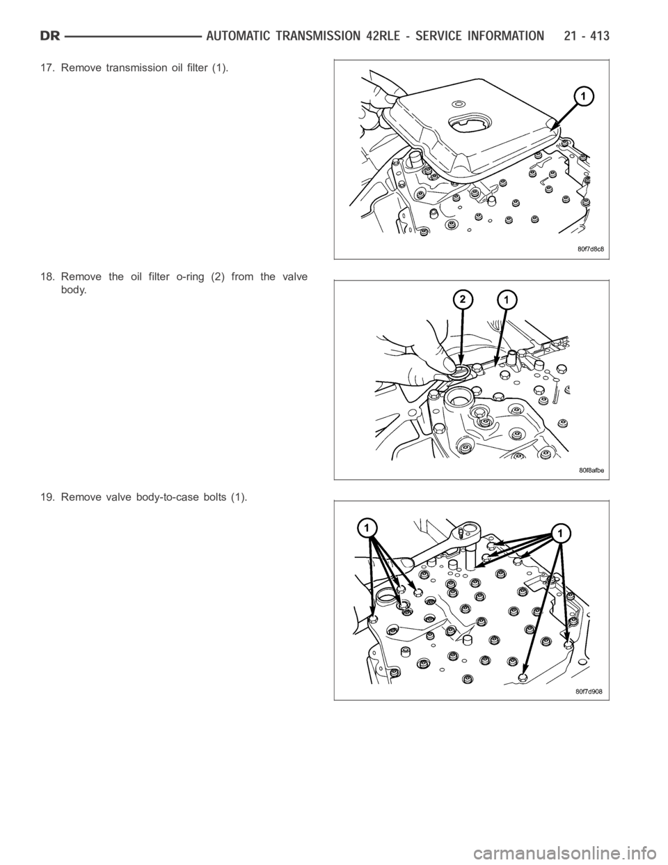
17. Remove transmission oil filter (1).
18. Remove the oil filter o-ring (2) from the valve
body.
19. Remove valve body-to-case bolts (1).
Page 2967 of 5267
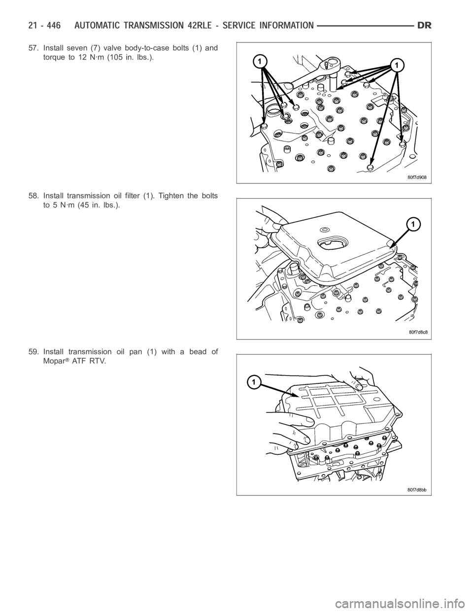
57. Install seven (7) valve body-to-case bolts (1) and
torque to 12 Nꞏm (105 in. lbs.).
58. Install transmission oil filter (1). Tighten the bolts
to5Nꞏm(45in.lbs.).
59. Install transmission oil pan (1) with a bead of
Mopar
AT F R T V.
Page 3001 of 5267
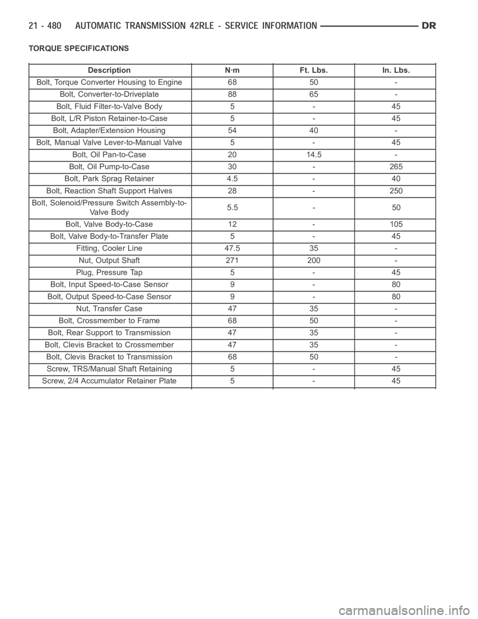
TORQUE SPECIFICATIONS
Description Nꞏm Ft. Lbs. In. Lbs.
Bolt, Torque Converter Housing to Engine 68 50 -
Bolt, Converter-to-Driveplate 88 65 -
Bolt, Fluid Filter-to-Valve Body 5 - 45
Bolt, L/R Piston Retainer-to-Case 5 - 45
Bolt, Adapter/Extension Housing 54 40 -
Bolt, Manual Valve Lever-to-Manual Valve 5 - 45
Bolt, Oil Pan-to-Case 20 14.5 -
Bolt, Oil Pump-to-Case 30 - 265
Bolt, Park Sprag Retainer 4.5 - 40
Bolt, Reaction Shaft Support Halves 28 - 250
Bolt, Solenoid/Pressure Switch Assembly-to-
Valve Body5.5 - 50
Bolt, Valve Body-to-Case 12 - 105
Bolt, Valve Body-to-Transfer Plate 5 - 45
Fitting, Cooler Line 47.5 35 -
Nut, Output Shaft 271 200 -
Plug, Pressure Tap 5 - 45
Bolt, Input Speed-to-Case Sensor 9 - 80
Bolt, Output Speed-to-Case Sensor 9 - 80
Nut, Transfer Case 47 35 -
Bolt, Crossmember to Frame 68 50 -
Bolt, Rear Support to Transmission 47 35 -
Bolt, Clevis Bracket to Crossmember 47 35 -
Bolt, Clevis Bracket to Transmission 68 50 -
Screw, TRS/Manual Shaft Retaining 5 - 45
Screw, 2/4 Accumulator Retainer Plate 5 - 45