2006 DODGE RAM SRT-10 oil filter
[x] Cancel search: oil filterPage 1904 of 5267
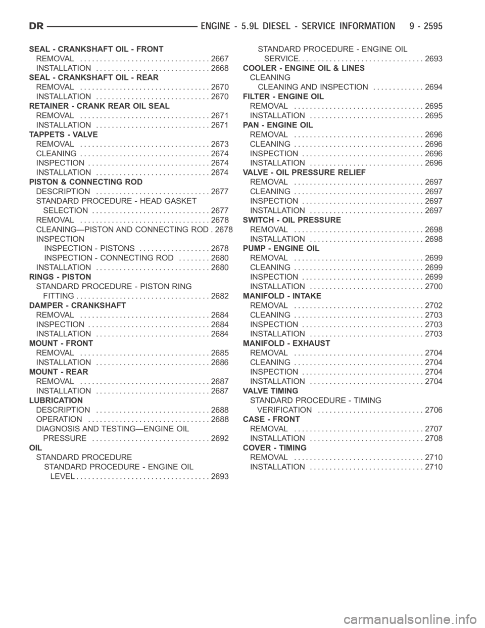
SEAL - CRANKSHAFT OIL - FRONT
REMOVAL ................................. 2667
INSTALLATION ............................. 2668
SEAL - CRANKSHAFT OIL - REAR
REMOVAL ................................. 2670
INSTALLATION ............................. 2670
RETAINER - CRANK REAR OIL SEAL
REMOVAL ................................. 2671
INSTALLATION ............................. 2671
TAPPETS - VALVE
REMOVAL ................................. 2673
CLEANING ................................. 2674
INSPECTION ............................... 2674
INSTALLATION ............................. 2674
PISTON & CONNECTING ROD
DESCRIPTION ............................. 2677
STANDARD PROCEDURE - HEAD GASKET
SELECTION .............................. 2677
REMOVAL ................................. 2678
CLEANING—PISTON AND CONNECTING ROD . 2678
INSPECTION
INSPECTION - PISTONS .................. 2678
INSPECTION - CONNECTING ROD........ 2680
INSTALLATION ............................. 2680
RINGS - PISTON
STANDARD PROCEDURE - PISTON RING
FITTING .................................. 2682
DAMPER - CRANKSHAFT
REMOVAL ................................. 2684
INSPECTION ............................... 2684
INSTALLATION ............................. 2684
MOUNT - FRONT
REMOVAL ................................. 2685
INSTALLATION ............................. 2686
MOUNT - REAR
REMOVAL ................................. 2687
INSTALLATION ............................. 2687
LUBRICATION
DESCRIPTION ............................. 2688
OPERATION ............................... 2688
DIAGNOSIS AND TESTING—ENGINE OIL
PRESSURE .............................. 2692
OIL
STANDARD PROCEDURE
STANDARD PROCEDURE - ENGINE OIL
LEVEL................................... 2693STANDARD PROCEDURE - ENGINE OIL
SERVICE................................. 2693
COOLER - ENGINE OIL & LINES
CLEANING
CLEANING AND INSPECTION............. 2694
FILTER - ENGINE OIL
REMOVAL ................................. 2695
INSTALLATION ............................. 2695
PA N - E N G I N E O I L
REMOVAL ................................. 2696
CLEANING ................................. 2696
INSPECTION............................... 2696
INSTALLATION ............................. 2696
VALVE-OILPRESSURERELIEF
REMOVAL ................................. 2697
CLEANING ................................. 2697
INSPECTION............................... 2697
INSTALLATION ............................. 2697
SWITCH - OIL PRESSURE
REMOVAL ................................. 2698
INSTALLATION ............................. 2698
PUMP - ENGINE OIL
REMOVAL ................................. 2699
CLEANING ................................. 2699
INSPECTION............................... 2699
INSTALLATION ............................. 2700
MANIFOLD - INTAKE
REMOVAL ................................. 2702
CLEANING ................................. 2703
INSPECTION............................... 2703
INSTALLATION ............................. 2703
MANIFOLD - EXHAUST
REMOVAL ................................. 2704
CLEANING ................................. 2704
INSPECTION............................... 2704
INSTALLATION ............................. 2704
VALVE TIMING
STANDARD PROCEDURE - TIMING
VERIFICATION ........................... 2706
CASE - FRONT
REMOVAL ................................. 2707
INSTALLATION ............................. 2708
COVER - TIMING
REMOVAL ................................. 2710
INSTALLATION ............................. 2710
Page 1907 of 5267
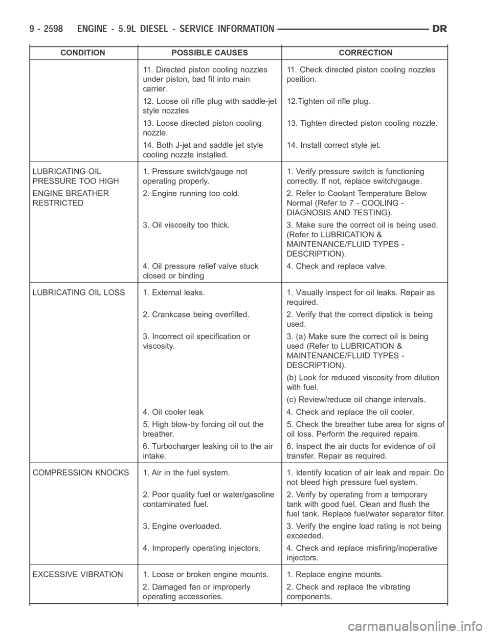
CONDITION POSSIBLE CAUSES CORRECTION
11. Directed piston cooling nozzles
under piston, bad fit into main
carrier.11. Check directed piston cooling nozzles
position.
12. Loose oil rifle plug with saddle-jet
style nozzles12.Tighten oil rifle plug.
13. Loose directed piston cooling
nozzle.13. Tighten directed piston cooling nozzle.
14. Both J-jet and saddle jet style
cooling nozzle installed.14. Install correct style jet.
LUBRICATING OIL
PRESSURE TOO HIGH1. Pressure switch/gauge not
operating properly.1. Verify pressure switch is functioning
correctly. If not, replace switch/gauge.
ENGINE BREATHER
RESTRICTED2. Engine running too cold. 2. Refer to Coolant Temperature Below
Normal (Refer to 7 - COOLING -
DIAGNOSIS AND TESTING).
3. Oil viscosity too thick. 3. Make sure the correct oil is being used.
(Refer to LUBRICATION &
MAINTENANCE/FLUID TYPES -
DESCRIPTION).
4. Oil pressure relief valve stuck
closed or binding4. Check and replace valve.
LUBRICATING OIL LOSS 1. External leaks. 1. Visually inspect for oil leaks.Repair as
required.
2. Crankcase being overfilled. 2. Verify that the correct dipstick is being
used.
3. Incorrect oil specification or
viscosity.3. (a) Make sure the correct oil is being
used (Refer to LUBRICATION &
MAINTENANCE/FLUID TYPES -
DESCRIPTION).
(b) Look for reduced viscosity from dilution
with fuel.
(c) Review/reduce oil change intervals.
4. Oil cooler leak 4. Check and replace the oil cooler.
5. High blow-by forcing oil out the
breather.5. Check the breather tube area for signs of
oil loss. Perform the required repairs.
6. Turbocharger leaking oil to the air
intake.6. Inspect the air ducts for evidence of oil
transfer. Repair as required.
COMPRESSION KNOCKS 1. Air in the fuel system. 1. Identify location of air leak and repair. Do
not bleed high pressure fuel system.
2. Poor quality fuel or water/gasoline
contaminated fuel.2. Verify by operating from a temporary
tank with good fuel. Clean and flush the
fuel tank. Replace fuel/water separator filter.
3. Engine overloaded. 3. Verify the engine load rating is not being
exceeded.
4. Improperly operating injectors. 4. Check and replace misfiring/inoperative
injectors.
EXCESSIVE VIBRATION 1. Loose or broken engine mounts. 1. Replace engine mounts.
2. Damaged fan or improperly
operating accessories.2. Check and replace the vibrating
components.
Page 1910 of 5267

EXCESSIVE WHITE SMOKE
POSSIBLE CAUSE CORRECTION
Fuel filter plugged. Refer to Powertrain Diagnostic Manual for fuel system
testing.
Fuel grade not correct or fuel quality is poor. Temporarily change fuel brands and note condition.
Change brand if necessary.
Fuel heater element or fuel heater temperature sensor
malfunctioning. This will cause wax type build-up in fuel
filter.Refer to Fuel Heater Testing (Refer to 14 - FUEL
SYSTEM/FUEL DELIVERY/FUEL HEATER -
DIAGNOSIS AND TESTING).
Fuel injector malfunctioning. A DTC should have been set. Perform “Cylinder
Performance Test
orCylinder cutout Testusing DRB
scan tool to isolate individual cylinders. Also refer to
Powertrain Diagnostic Procedures Information and,
(Refer to 14 - FUEL SYSTEM/FUEL INJECTION/FUEL
INJECTOR - DIAGNOSIS AND TESTING).
Fuel injector hold-downs loose. Torque to specifications.
Fuel injector protrusion not correct. Check washer (shim) at bottom of fuel injector for
correct thickness. (Referto 14 - FUEL SYSTEM/FUEL
INJECTION/FUEL INJECTOR - INSTALLATION)
Fuel injection pump malfunctioning. A DTC should have been set. Refer to Powertrain
Diagnostic Procedures Information.
Fuel supply side restriction. Refer to Powertrain Diagnostic Manual for fuel system
testing.
Fuel transfer (lift) pump malfunctioning. A DTC may have been set. Refer toPowertrain
Diagnostic Procedures Information.
Intake/Exhaust valve adjustments not correct (too tight). (Refer to 9 - ENGINE/CYLINDER HEAD/INTAKE/
EXHAUST VALVES & SEATS - STANDARD
PROCEDURE).
Intake manifold air temperature sensor malfunctioning. A DTC should havebeen set. Refer to Powertrain
Diagnostic Procedures Information.
Intake manifold heater circuit not functioning correctly in
cold weather.A DTC should have been set. Refer to Powertrain
Diagnostic Procedures Information. Also check heater
elements for correct operation.
Intake manifold heater elements not functioning
correctly in cold weather.A DTC should have been set if heater elements are
malfunctioning. Refer to Powertrain Diagnostic
Procedures Information.
Internal engine damage (scuffed cylinder). Analyze engine oil and inspect oil filter to locate area of
probable damage.
Restriction in fuel supply side of fuel system. Refer to Powertrain Diagnostic Manual for fuel system
testing.
EXCESSIVE BLUE SMOKE
POSSIBLE CAUSE CORRECTION
Dirty air cleaner or restricted turbocharger intake duct. Check Filter Minder
at air filter housing. (Refer to 9 -
ENGINE/AIR INTAKE SYSTEM/AIR CLEANER
ELEMENT - REMOVAL).
Air leak in boost system between turbocharger
compressor outlet and intake manifold.Service air charge system..
Obstruction in exhaust manifold. Remove exhaust manifold and inspect forblockage
(Refer to 9 - ENGINE/MANIFOLDS/EXHAUST
MANIFOLD - REMOVAL).
Page 1911 of 5267
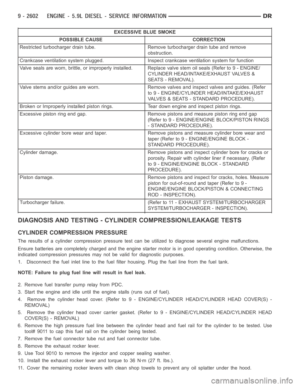
EXCESSIVE BLUE SMOKE
POSSIBLE CAUSE CORRECTION
Restricted turbocharger drain tube. Remove turbocharger drain tube and remove
obstruction.
Crankcase ventilation system plugged. Inspect crankcase ventilation system for function
Valve seals are worn, brittle, or improperly installed. Replace valve stemoilseals(Referto9-ENGINE/
CYLINDER HEAD/INTAKE/EXHAUST VALVES &
SEATS - REMOVAL).
Valve stems and/or guides are worn. Remove valves and inspect valves and guides. (Refer
to 9 - ENGINE/CYLINDER HEAD/INTAKE/EXHAUST
VALVES & SEATS - STANDARD PROCEDURE).
Broken or Improperly installed piston rings. Tear down engine and inspectpiston rings.
Excessive piston ring end gap. Remove pistons and measure piston ring end gap
(Refer to 9 - ENGINE/ENGINE BLOCK/PISTON RINGS
- STANDARD PROCEDURE).
Excessive cylinder bore wear and taper. Remove pistons and measure cylinder bore wear and
taper (Refer to 9 - ENGINE/ENGINE BLOCK -
STANDARD PROCEDURE).
Cylinder damage. Remove pistons and inspect cylinder bore for cracks or
porosity. Repair with cylinder liner if necessary. (Refer
to 9 - ENGINE/ENGINE BLOCK - STANDARD
PROCEDURE).
Piston damage. Remove pistons and inspect for cracks, holes. Measure
piston for out-of-round and taper (Refer to 9 -
ENGINE/ENGINE BLOCK/PISTON & CONNECTING
ROD - INSPECTION).
Turbocharger failure. (Refer to 11 - EXHAUST SYSTEM/TURBOCHARGER
SYSTEM/TURBOCHARGER - INSPECTION).
DIAGNOSIS AND TESTING - CYLINDER COMPRESSION/LEAKAGE TESTS
CYLINDER COMPRESSION PRESSURE
The results of a cylinder compressionpressure test can be utilized to diagnose several engine malfunctions.
Ensure batteries are completely charged and the engine starter motor is ingood operating condition. Otherwise, the
indicated compression pressures may not be valid for diagnostic purposes.
1. Disconnect the fuel inlet line to the fuel filter housing. Plug the fuel line from the fuel tank.
NOTE: Failure to plug fuel line will result in fuel leak.
2. Remove fuel transfer pump relay from PDC.
3. Start the engine and idle until the engine stalls (runs out of fuel).
4. Remove the cylinder head cover. (Refer to 9 - ENGINE/CYLINDER HEAD/CYLINDER HEAD COVER(S) -
REMOVAL)
5. Remove the cylinder head cover carrier gasket. (Refer to 9 - ENGINE/CYLINDER HEAD/CYLINDER HEAD
COVER(S) - REMOVAL)
6. Remove the high pressure fuel line between the cylinder head and fuel rail for the cylinder to be tested. Use
tool# 9011 to cap this fuel rail on the cylinder being tested.
7. Remove the fuel connector tube nut and fuel connector tube.
8. Remove the exhaust rocker lever.
9. Use Tool 9010 to remove the injector and copper sealing washer.
10. Install the exhaust rocker lever and torque to 36 Nꞏm (27 ft. lbs.).
11. Cover the remaining rocker levers with clean shop towels to prevent anyoil splatter under the hood.
Page 1914 of 5267
3. Place a shop towel around the fuel injectors to catch any fluid that may possibly be under pressure in the cyl-
inder head. Remove the fuel injectors (Refer to 14 - FUEL SYSTEM/FUEL INJECTION/FUEL INJECTOR -
REMOVAL).
4. With all injectors removed, rotatethe crankshaft using the crankshaftbarring tool (PN 7471–B).
5. Identify the fluid in the cylinders (coolant, fuel, oil, etc.).
6. Be sure all fluid has been removed from the cylinders.
7. Repair engine or components as necessary to prevent this problem from occurring again.
8. Squirt a small amount of engine oil into the cylinders to lubricate the walls. This will prevent damage on restart.
9. Install fuel injectors (Refer to 14 - FUEL SYSTEM/FUEL INJECTION/FUEL INJECTOR - INSTALLATION).
10. Drain engine oil. Remove and discard the oil filter (Refer to 9 - ENGINE/LUBRICATION/OIL FILTER -
REMOVAL).
11. Installthedrainplug.Tightentheplugto50Nꞏm(37ft.lbs.)torque.
12. Install a new oil filter (Refer to 9 - ENGINE/LUBRICATION/OIL FILTER - INSTALLATION).
13. Fill engine crankcase with the specified amount and grade of oil (Referto LUBRICATION & MAINTENANCE/
FLUID TYPES - SPECIFICATIONS).
14. Connect the negative cable(s) to the battery.
15. Start the engine and check for any leaks.
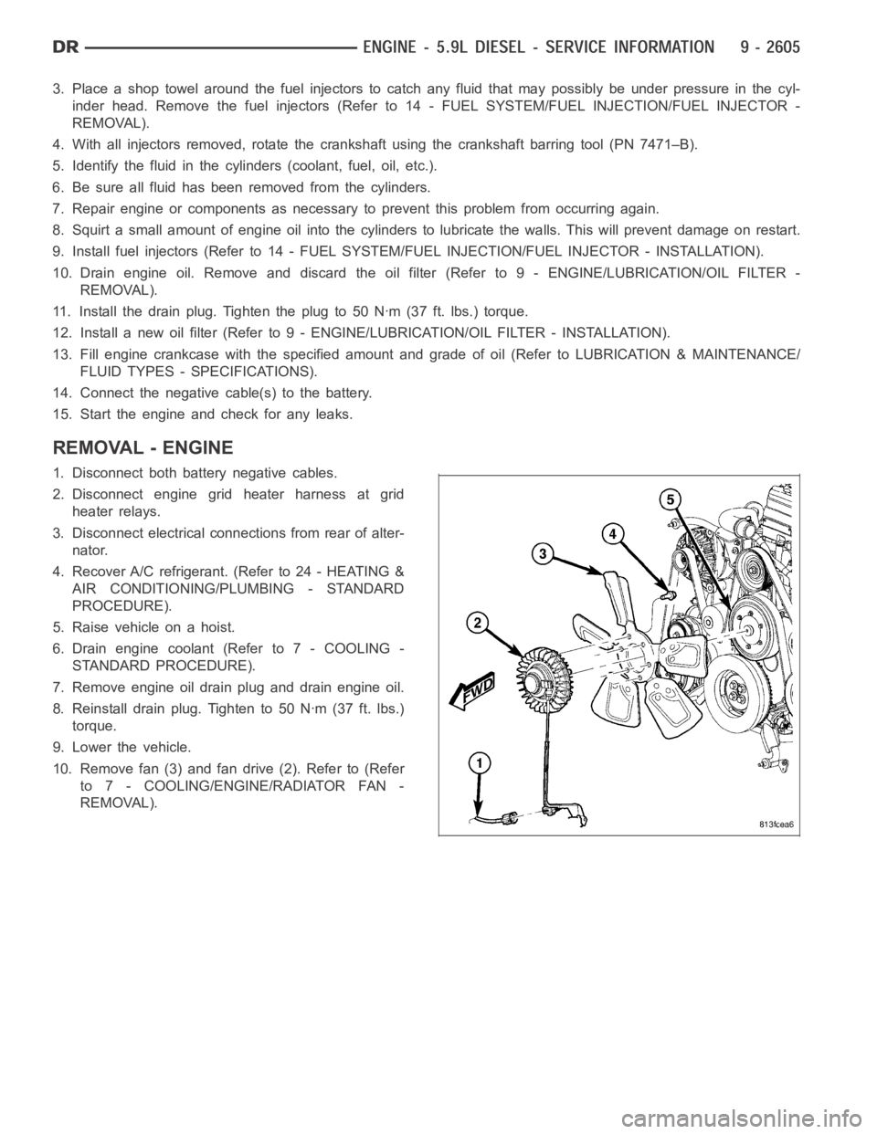
REMOVAL - ENGINE
1. Disconnect both battery negative cables.
2. Disconnect engine grid heater harness at grid
heater relays.
3. Disconnect electrical connections from rear of alter-
nator.
4. Recover A/C refrigerant. (Refer to 24 - HEATING &
AIR CONDITIONING/PLUMBING - STANDARD
PROCEDURE).
5. Raise vehicle on a hoist.
6. Drain engine coolant (Refer to 7 - COOLING -
STANDARD PROCEDURE).
7. Remove engine oil drain plug and drain engine oil.
8. Reinstall drain plug. Tighten to 50 Nꞏm (37 ft. lbs.)
torque.
9. Lower the vehicle.
10. Remove fan (3) and fan drive (2). Refer to (Refer
to 7 - COOLING/ENGINE/RADIATOR FAN -
REMOVAL).
Page 1924 of 5267
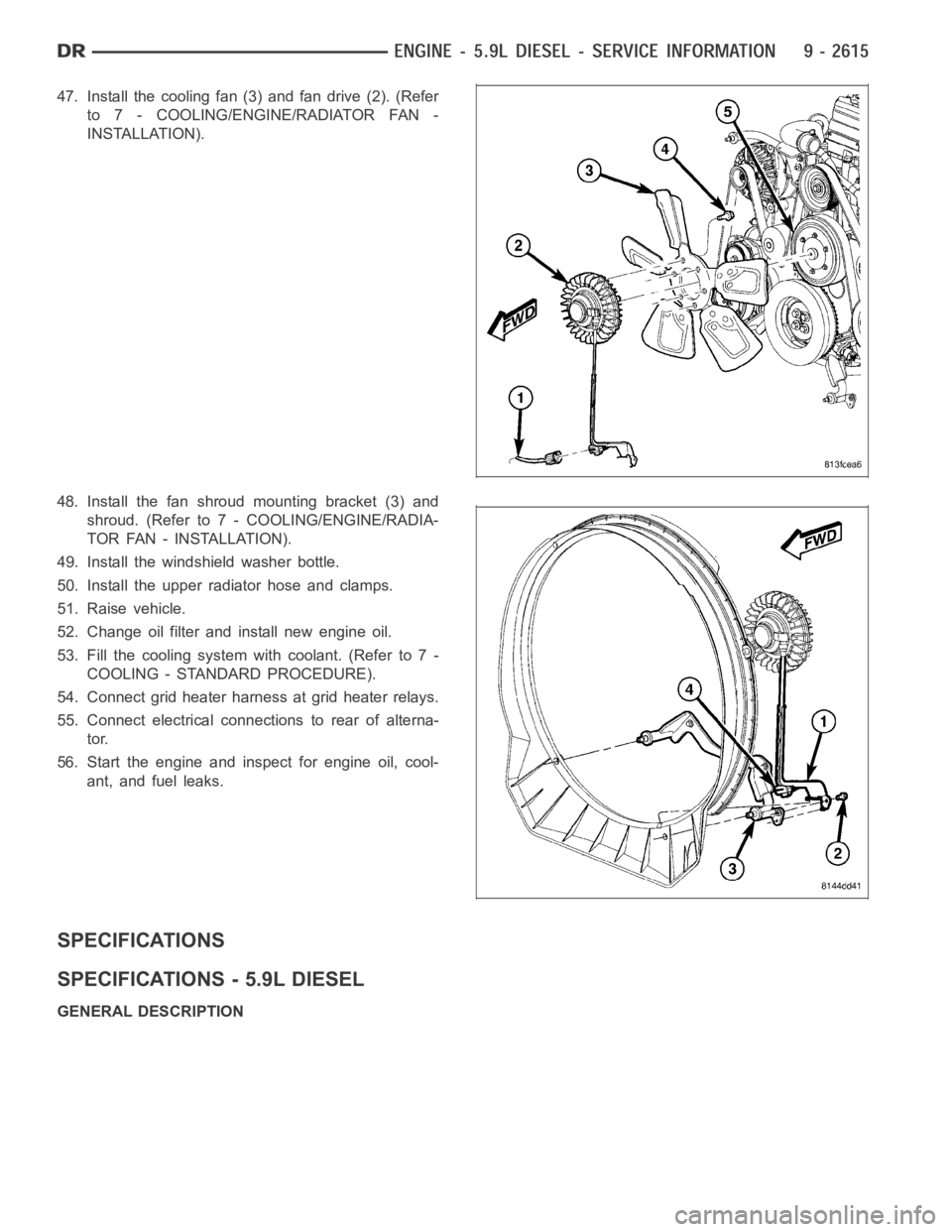
47. Install the cooling fan (3) and fan drive (2). (Refer
to 7 - COOLING/ENGINE/RADIATOR FAN -
INSTALLATION).
48. Install the fan shroud mounting bracket (3) and
shroud. (Refer to 7 - COOLING/ENGINE/RADIA-
TOR FAN - INSTALLATION).
49. Install the windshield washer bottle.
50. Install the upper radiator hose and clamps.
51. Raise vehicle.
52. Change oil filter and install new engine oil.
53. Fill the cooling system with coolant. (Refer to 7 -
COOLING - STANDARD PROCEDURE).
54. Connect grid heater harness at grid heater relays.
55. Connect electrical connections to rear of alterna-
tor.
56. Start the engine and inspect for engine oil, cool-
ant, and fuel leaks.
SPECIFICATIONS
SPECIFICATIONS - 5.9L DIESEL
GENERAL DESCRIPTION
Page 1926 of 5267
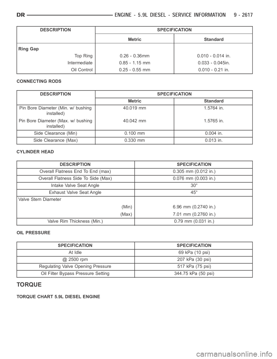
DESCRIPTION SPECIFICATION
Metric Standard
Ring Gap
Top Ring 0.26 - 0.36mm 0.010 - 0.014 in.
Intermediate 0.85 - 1.15 mm 0.033 - 0.045in.
Oil Control 0.25 - 0.55 mm 0.010 - 0.21 in.
CONNECTING RODS
DESCRIPTION SPECIFICATION
Metric Standard
Pin Bore Diameter (Min. w/ bushing
installed)40.019 mm 1.5764 in.
Pin Bore Diameter (Max. w/ bushing
installed)40.042 mm 1.5765 in.
Side Clearance (Min) 0.100 mm 0.004 in.
Side Clearance (Max) 0.330 mm 0.013 in.
CYLINDER HEAD
DESCRIPTION SPECIFICATION
Overall Flatness End To End (max) 0.305 mm (0.012 in.)
Overall Flatness Side To Side (Max) 0.076 mm (0.003 in.)
Intake Valve Seat Angle 30°
Exhaust Valve Seat Angle 45°
Va l v e S t e m D i a m e t e r
(Min) 6.96 mm (0.2740 in.)
(Max) 7.01 mm (0.2760 in.)
Valve Rim Thickness (Min.) 0.79 mm (0.031 in.)
OIL PRESSURE
SPECIFICATION SPECIFICATION
At Idle 69 kPa (10 psi)
@ 2500 rpm 207 kPa (30 psi)
Regulating Valve Opening Pressure 517 kPa (75 psi)
Oil Filter Bypass Pressure Setting 344.75 kPa (50 psi)
TORQUE
TORQUE CHART 5.9L DIESEL ENGINE
Page 1933 of 5267
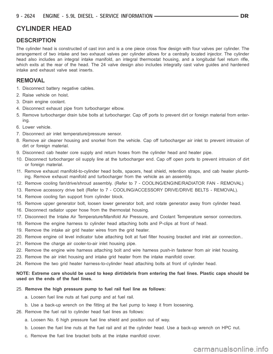
CYLINDER HEAD
DESCRIPTION
The cylinder head is constructed of cast iron and is a one piece cross flow design with four valves per cylinder. The
arrangement of two intake and two exhaust valves per cylinder allows for a centrally located injector. The cylinder
head also includes an integral intake manifold, an integral thermostat housing, and a longitudal fuel return rifle,
which exits at the rear of the head. The 24 valve design also includes integrally cast valve guides and hardened
intake and exhaust valve seat inserts.
REMOVAL
1. Disconnect battery negative cables.
2. Raise vehicle on hoist.
3. Drain engine coolant.
4. Disconnect exhaust pipe from turbocharger elbow.
5. Remove turbocharger drain tube bolts at turbocharger. Cap off ports to prevent dirt or foreign material from enter-
ing.
6. Lower vehicle.
7. Disconnect air inlet temperature/pressure sensor.
8. Remove air cleaner housing and snorkel from the vehicle. Cap off turbocharger air inlet to prevent intrusion of
dirt or foreign material.
9. Disconnect cab heater core supply and return hoses from the cylinder head and heater pipe.
10. Disconnect turbocharger oil supply line at the turbocharger end. Cap off open ports to prevent intrusion of dirt
or foreign material.
11. Remove exhaust manifold-to-cylinder head bolts, spacers, heat shield, retention straps, and cab heater plumb-
ing. Remove exhaust manifold and turbocharger from the vehicle as an assembly.
12. Remove cooling fan/drive/shroud assembly. (Refer to 7 - COOLING/ENGINE/RADIATOR FAN - REMOVAL)
13. Remove accessory drive belt (Refer to 7 - COOLING/ACCESSORY DRIVE/DRIVE BELTS - REMOVAL).
14. Remove cooling fan support from cylinder block.
15. Remove upper generator bolt, loosen lower generator bolt, and rotate generator away from cylinder head.
16. Disconnect radiator upper hose from the thermostat housing.
17. Disconnect the Intake Air Temperature/Manifold Air Pressure, and Coolant Temperature sensor connectors.
18. Remove the engine harness to cylinder head attaching bolts and P-clipsat front of head.
19. Remove the intake air grid heater wires from the grid heater.
20. Remove engine oil level indicator tube attaching bolt at fuel filter housing bracket and inlet air connection..
21. Remove the charge air cooler-to-air inlet housing pipe.
22. Remove the engine wire harness attaching bolt and wire harness push-infastener from air inlet housing.
23. Remove the air inlet housing and intake grid heater from the intake manifold cover.
24. Remove the two grid heater harness-to-cylinder head attaching bolts at front of cylinder head.
NOTE: Extreme care should be used to keep dirt/debris from entering the fuel lines. Plastic caps should be
used on the ends of the fuel lines.
25.Remove the high pressure pump to fuel rail fuel line as follows:
a. Loosen fuel line nuts at fuel pump and at fuel rail.
b. Use a back-up wrench on the fitting at the fuel pump to keep it from loosening.
26. Remove the fuel rail to cylinder head fuel lines as follows:
a. Loosen No. 6 high pressure fuel line shield and position out of way.
b. Loosen the fuel line nuts at the fuel rail and at the cylinder head. Use a back-up wrench on HPC nut.
c. Remove the fuel line bracket bolts at the intake manifold cover.