2006 DODGE RAM SRT-10 oil filter
[x] Cancel search: oil filterPage 1764 of 5267
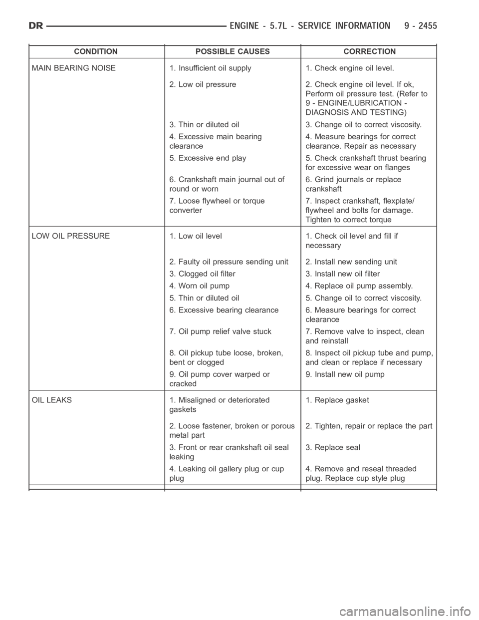
CONDITION POSSIBLE CAUSES CORRECTION
MAIN BEARING NOISE 1. Insufficient oil supply 1. Check engine oil level.
2. Low oil pressure 2. Check engine oil level. If ok,
Perform oil pressure test. (Refer to
9 - ENGINE/LUBRICATION -
DIAGNOSIS AND TESTING)
3. Thin or diluted oil 3. Change oil to correct viscosity.
4. Excessive main bearing
clearance4. Measure bearings for correct
clearance. Repair as necessary
5. Excessive end play 5. Check crankshaft thrust bearing
for excessive wear on flanges
6. Crankshaft main journal out of
round or worn6. Grind journals or replace
crankshaft
7. Loose flywheel or torque
converter7. Inspect crankshaft, flexplate/
flywheel and bolts for damage.
Tighten to correct torque
LOW OIL PRESSURE 1. Low oil level 1. Check oil level and fill if
necessary
2. Faulty oil pressure sending unit 2. Install new sending unit
3. Clogged oil filter 3. Install new oil filter
4. Worn oil pump 4. Replace oil pump assembly.
5. Thin or diluted oil 5. Change oil to correct viscosity.
6. Excessive bearing clearance 6. Measure bearings for correct
clearance
7. Oil pump relief valve stuck 7. Remove valve to inspect, clean
and reinstall
8. Oil pickup tube loose, broken,
bent or clogged8. Inspect oil pickup tube and pump,
and clean or replace if necessary
9. Oil pump cover warped or
cracked9. Install new oil pump
OIL LEAKS 1. Misaligned or deteriorated
gaskets1. Replace gasket
2. Loose fastener, broken or porous
metal part2. Tighten, repair or replace the part
3. Front or rear crankshaft oil seal
leaking3. Replace seal
4. Leaking oil gallery plug or cup
plug4. Remove and reseal threaded
plug. Replace cup style plug
Page 1765 of 5267

CONDITION POSSIBLE CAUSES CORRECTION
EXCESSIVE OIL CONSUMPTION
OR SPARK PLUGS OIL FOULED1. CCV System malfunction 1. (Refer to 25 - EMISSIONS
CONTROL/EVAPORATIVE
EMISSIONS - DESCRIPTION) for
correct operation
2. Defective valve stem seal(s) 2. Repair or replace seal(s)
3. Worn or broken piston rings 3. Hone cylinder bores. Install new
rings
4. Scuffed pistons/cylinder walls 4. Hone cylinder bores and replace
pistons as required
5. Carbon in oil control ring groove 5. Remove rings and de-carbon
piston
6. Worn valve guides 6. Inspect/replace valve guides as
necessary
7. Piston rings fitted too tightly in
grooves7. Remove rings and check ring end
gap and side clearance. Replace if
necessary
STANDARD PROCEDURE
STANDARD PROCEDURE - REPAIR DAMAGED OR WORN THREADS
CAUTION: Be sure that the tapped holes maintain the original center line.
Damaged or worn threads can be repaired. Essentially, this repair consistsof:
Drilling out worn or damaged threads.
Tapping the hole with a special Heli-Coil Tap, or equivalent.
Installing an insert into the tapped hole to bring the hole back to its original thread size.
STANDARD PROCEDURE—HYDROSTATIC LOCK
CAUTION: DO NOT use the starter motor to rotate the crankshaft. Severe damage could occur.
When an engine is suspected of hydrostatic lock (regardless of what causedthe problem), follow the steps below.
1. Perform the Fuel Pressure Release Procedure (Refer to 14 - FUEL SYSTEM/FUEL DELIVERY - STANDARD
PROCEDURE).
2. Disconnect the negative cable(s) from the battery.
3. Inspect air cleaner, induction system, and intake manifold to ensure system is dry and clear of foreign material.
4. Place a shop towel around the spark plugs to catch any fluid that may possibly be under pressure in the cylinder
head. Remove the spark plugs.
5. With all spark plugs removed, rotate the crankshaft using a breaker bar and socket.
6. Identify the fluid in the cylinders (coolant, fuel, oil, etc.).
7. Be sure all fluid has been removed from the cylinders.
8. Repair engine or components as necessary to prevent this problem from occurring again.
9. Squirt a small amount of engine oil into the cylinders to lubricate the walls. This will prevent damage on restart.
10. Install new spark plugs. Tighten the spark plugs to 41 Nꞏm (30 ft. lbs.) torque.
11. Drain engine oil. Remove and discard the oil filter.
12. Install the drain plug. Tighten the plug to 34 Nꞏm (25 ft. lbs.) torque.
13. Install a new oil filter.
14. Fill engine crankcase with the specified amount and grade of oil. (Refer to LUBRICATION & MAINTENANCE -
SPECIFICATIONS).
Page 1824 of 5267
ENGINE BLOCK
CLEANING
Thoroughly clean the oil pan and engine block gasket surfaces.
Use compressed air to clean out:
The galley at the oil filter adaptor hole.
The front and rear oil galley holes.
The feed holes for the crankshaft main bearings.
Once the block has been completely cleaned, apply Loctite PST pipe sealantwith Teflon 592 to the threads of the
front and rear oil galley plugs. Tighten the 1/4 inch NPT plugs to 20 Nꞏm (177in. lbs.) torque. Tighten the 3/8 inch
NPT plugs to 27 Nꞏm (240 in. lbs.) torque.
INSPECTION
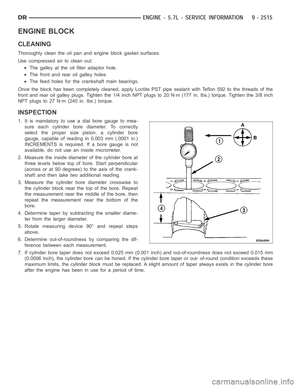
1. It is mandatory to use a dial bore gauge to mea-
sure each cylinder bore diameter. To correctly
select the proper size piston, a cylinder bore
gauge, capable of reading in 0.003 mm (.0001 in.)
INCREMENTS is required. If a bore gauge is not
available, do not use an inside micrometer.
2. Measure the inside diameter of the cylinder bore at
three levels below top of bore. Start perpendicular
(across or at 90 degrees) to the axis of the crank-
shaft and then take two additional reading.
3. Measure the cylinder bore diameter crosswise to
the cylinder block near the top of the bore. Repeat
the measurement near the middle of the bore, then
repeat the measurement near the bottom of the
bore.
4. Determine taper by subtracting the smaller diame-
ter from the larger diameter.
5. Rotate measuring device 90° and repeat steps
above.
6. Determine out-of-roundness by comparing the dif-
ference between each measurement.
7. If cylinder bore taper does not exceed 0.025 mm (0.001 inch) and out-of-roundness does not exceed 0.015 mm
(0.0006 inch), the cylinder bore can be honed. If the cylinder bore taper orout- of-round condition exceeds these
maximum limits, the cylinder block must be replaced. A slight amount of taper always exists in the cylinder bore
after the engine has been in use for a period of time.
Page 1848 of 5267
SEAL - CRANKSHAFT OIL - REAR
DIAGNOSIS AND TESTING - REAR SEAL AREA LEAKS
Since it is sometimes difficult to determine the source of an oil leak in therear seal area of the engine, a more
involved inspection is necessary. The following steps should be followedto help pinpoint the source of the leak.
If the leakage occurs at the crankshaft rear oil seal area:
1. Disconnect the battery.
2. Raise the vehicle.
3. Remove torque converter or clutch housing cover and inspect rear of block for evidence of oil. Use a black light
to check for the oil leak:
a. Circular spray pattern generally indicates seal leakage or crankshaftdamage.
b. Where leakage tends to run straight down, possible causes are a porous block, camshaft bore cup plugs, oil
galley pipe plugs, oil filter runoff, and main bearing cap to cylinder block mating surfaces. See Engine, for
proper repair procedures of these items.
4. If no leaks are detected, pressurized the crankcase as outlined in the section, Inspection (Engine oil Leaks in
general)
CAUTION: Do not exceed 20.6 kPa (3 psi).
5. If the leak is not detected, very slowly turn the crankshaft and watch forleakage. If a leak is detected between
the crankshaft and seal while slowly turning the crankshaft, it is possible the crankshaft seal surface is damaged.
The seal area on the crankshaft could have minor nicks or scratches that canbe polished out with emery cloth.
CAUTION: Use extreme caution when crankshaft polishing is necessary to remove minor nicks or
scratches. The crankshaft seal flange is specially machined to complement the function of the rear oil seal.
6. For bubbles that remain steady with shaft rotation, no further inspection can be done until disassembled. (Refer
to 9 - ENGINE - DIAGNOSIS AND TESTING), under the Oil Leak row, for components inspections on possible
causes and corrections.
7. After the oil leak root cause and appropriate corrective action have been identified, (Refer to 9 - ENGINE/EN-
GINE BLOCK/CRANKSHAFT OIL SEAL - REAR - REMOVAL).
REMOVAL
NOTE: This procedure can be performed in vehi-
cle.
1. If being performed in vehicle, remove the transmis-
sion.
2. Remove the flexplate (Refer to 9 - ENGINE/EN-
GINE BLOCK/FLEX PLATE - REMOVAL).
NOTE: The crankshaft oil seal CAN NOT be reused
after removal.
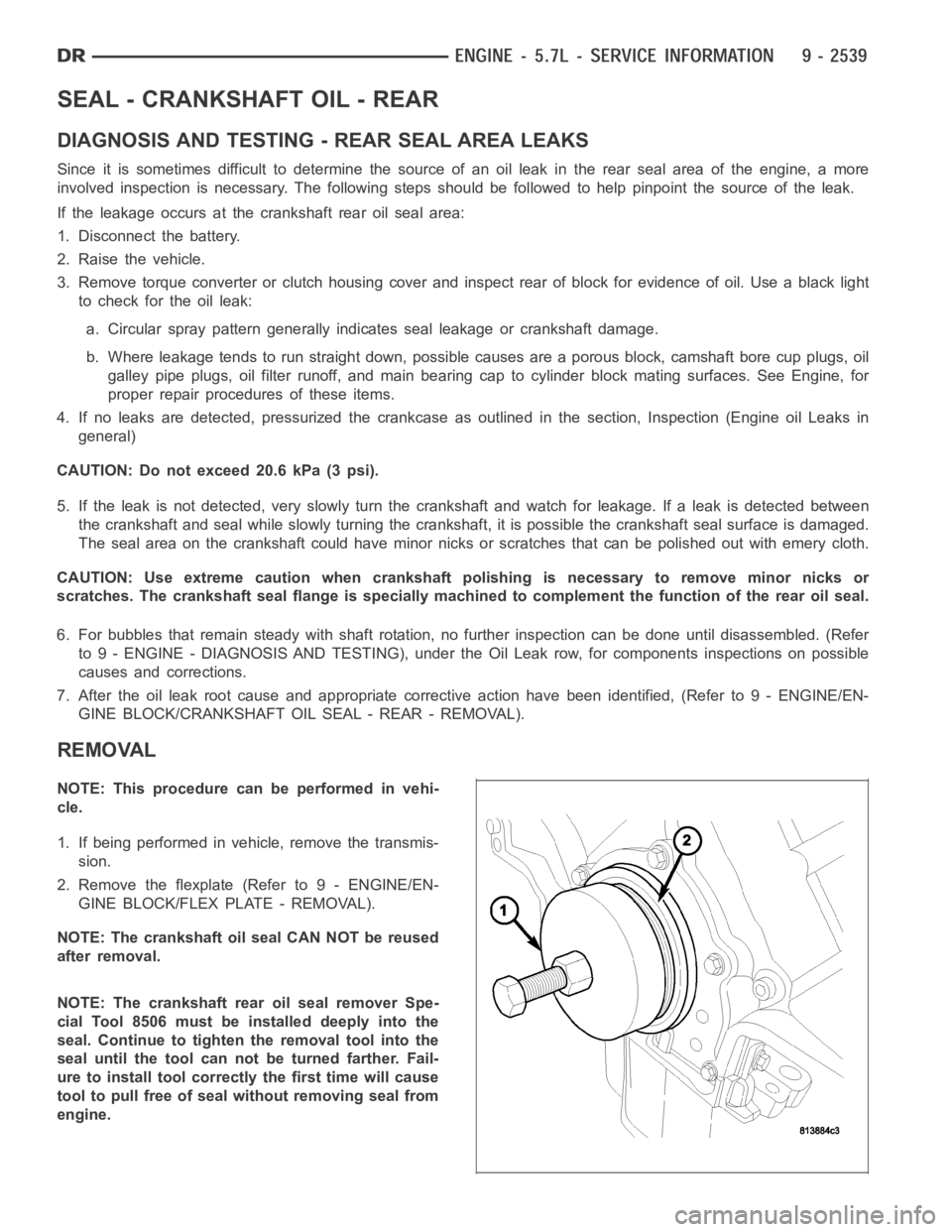
NOTE: The crankshaft rear oil seal remover Spe-
cial Tool 8506 must be installed deeply into the
seal. Continue to tighten the removal tool into the
seal until the tool can not be turned farther. Fail-
ure to install tool correctly the first time will cause
tool to pull free of seal without removing seal from
engine.
Page 1871 of 5267
4WD
1. Disconnect the negative cable from the battery.
2. Raise the vehicle.
3. Removetheskidplate.
4. Remove the front crossmember (Refer to 13 - FRAME & BUMPERS/FRAME/FRONTCROSSMEMBER -
REMOVAL).
5. Remove the engine oil filter.
6. Support the engine using engine support fixture, special tool # 8534.
7. Support the front axle with a suitable jack.
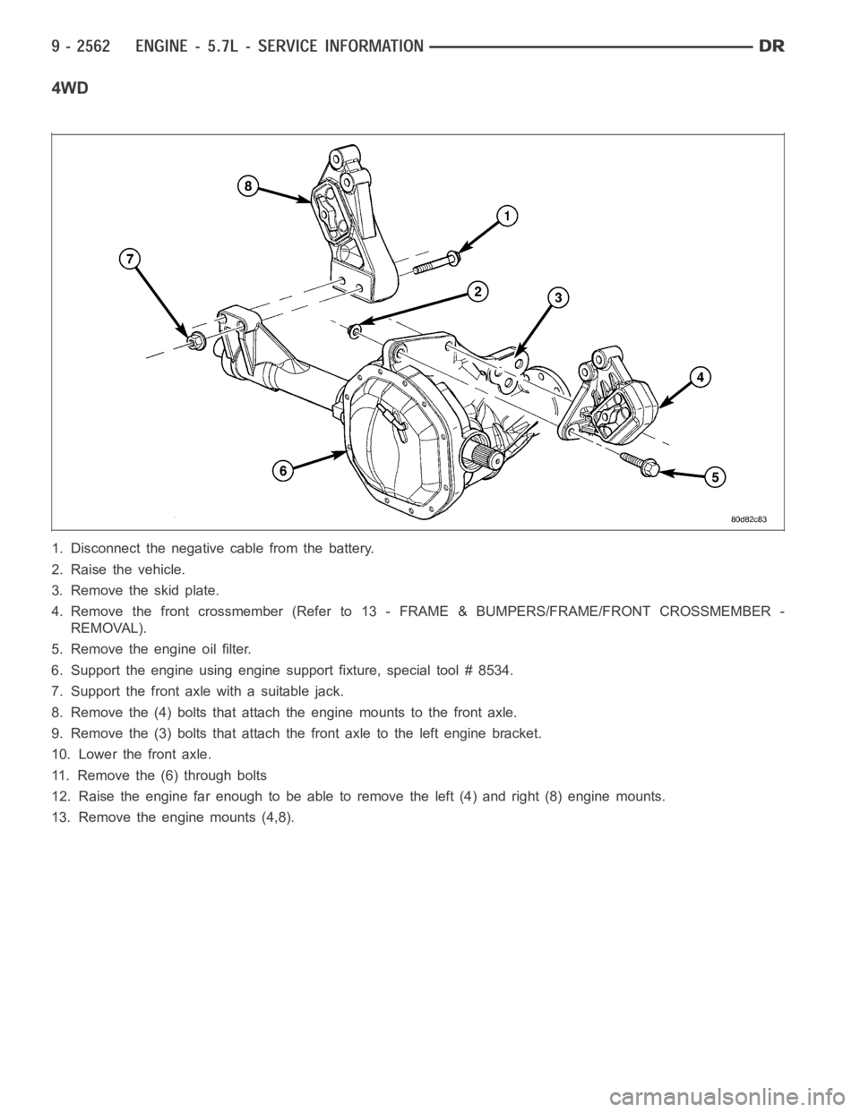
8. Remove the (4) bolts that attach the engine mounts to the front axle.
9. Remove the (3) bolts that attach the front axle to the left engine bracket.
10. Lower the front axle.
11. Remove the (6) through bolts
12. Raise the engine far enough to be able to remove the left (4) and right (8)engine mounts.
13. Remove the engine mounts (4,8).
Page 1873 of 5267
3. Insert the two upper through bolts into the right and left side engine mounts and loose assemble the two nuts
onto the through bolts.
4. Lower the engine using engine support fixture special tool # 8534, untilthe left and right side engine brackets
rest on the through bolts, and the lower engine bracket through holes alignwith the engine mounts, and the left
engine bracket holes align with the front axle slots.
5. Loose assemble the 3 bolts that attach the front axle to the left engine bracket.
6. Loose assemble the lower through bolts.
7. Torque the nuts for the 4 through bolts to 101 Nꞏm (75 ft. lbs.).
8. Torque the 3 bolts that attach the front axle to the left engine bracket to101Nꞏm(75ft.lbs.).
9. Install the engine oil filter, if removed.
10. Install the front crossmember (Refer to 13 - FRAME & BUMPERS/FRAME/FRONT CROSSMEMBER - INSTAL-
LATION).
11. Install the skid plate.
12. Lower the vehicle.
13. Reconnect the negative battery cable.
Page 1876 of 5267
b. Where leakage tends to run straight down, possible causes are a porous block, distributor seal, camshaft
bore cup plugs oil galley pipe plugs, oil filter runoff, and main bearing cap to cylinder block mating surfaces.
4. If no leaks are detected, pressurize the crankcase as outlined in the, Inspection (Engine oil Leaks in general)
CAUTION: Do not exceed 20.6 kPa (3 psi).
5. If the leak is not detected, very slowly turn the crankshaft and watch forleakage. If a leak is detected between
the crankshaft and seal while slowly turning the crankshaft, it is possible the crankshaft seal surface is damaged.
The seal area on the crankshaft could have minor nicks or scratches that canbe polished out with emery cloth.
CAUTION: Use extreme caution when crankshaft polishing is necessary to remove minor nicks and
scratches. The crankshaft seal flange is especially machined to complement the function of the rear oil seal.
6. For bubbles that remain steady with shaft rotation, no further inspection can be done until disassembled.
Page 1878 of 5267
FILTER - ENGINE OIL
REMOVAL
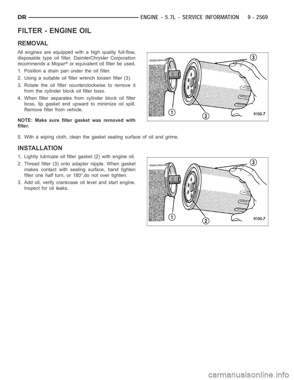
All engines are equipped with a high quality full-flow,
disposable type oil filter. DaimlerChrysler Corporation
recommends a Mopar
or equivalent oil filter be used.
1. Position a drain pan under the oil filter.
2. Using a suitable oil filter wrench loosen filter (3).
3. Rotate the oil filter counterclockwise to remove it
from the cylinder block oil filter boss.
4. When filter separates from cylinder block oil filter
boss, tip gasket end upward to minimize oil spill.
Remove filter from vehicle.
NOTE: Make sure filter gasket was removed with
filter.
5. With a wiping cloth, clean the gasket sealing surface of oil and grime.
INSTALLATION
1. Lightly lubricate oil filter gasket (2) with engine oil.
2. Thread filter (3) onto adapter nipple. When gasket
makes contact with sealing surface, hand tighten
filter one half turn, or 180°,do not over tighten.
3. Add oil, verify crankcase oil level and start engine.
Inspect for oil leaks.