2006 DODGE RAM SRT-10 manual transmission
[x] Cancel search: manual transmissionPage 3300 of 5267
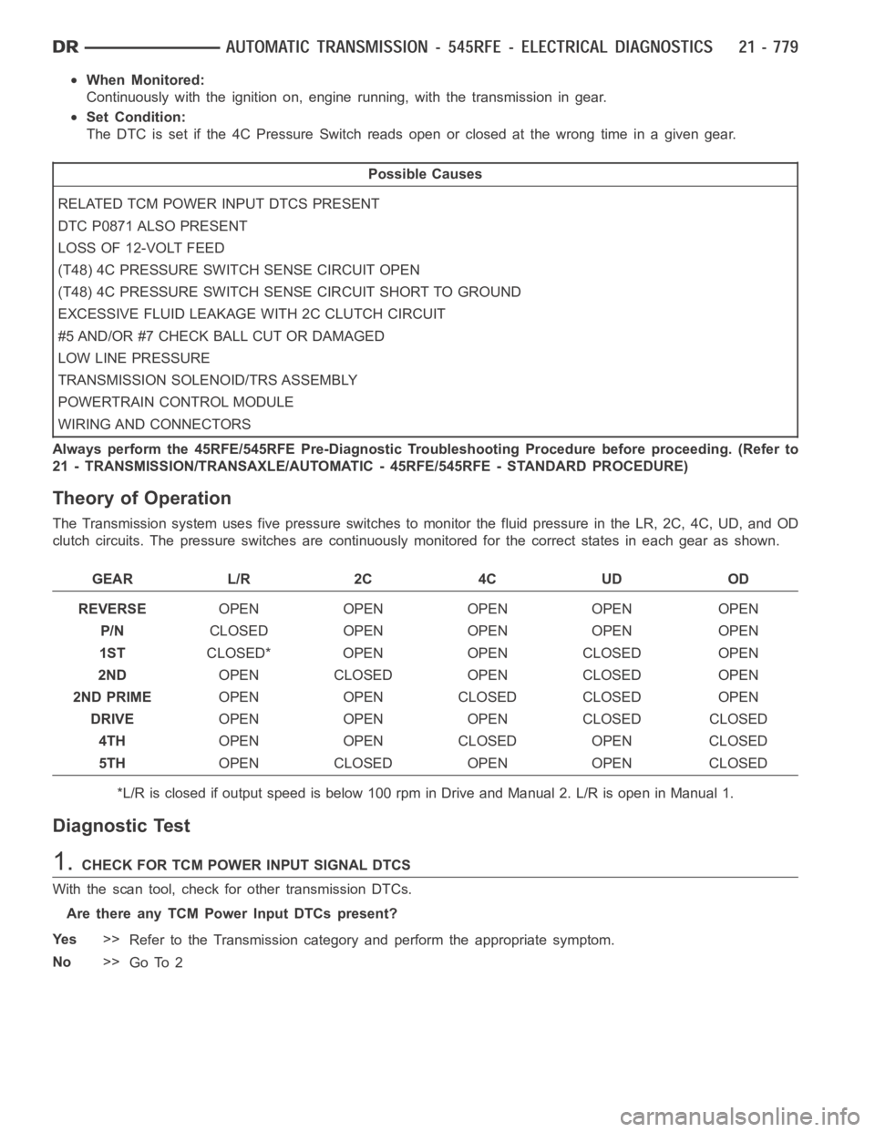
When Monitored:
Continuously with the ignition on, engine running, with the transmissionin gear.
Set Condition:
The DTC is set if the 4C Pressure Switchreadsopenorclosedatthewrongtimein a given gear.
Possible Causes
RELATED TCM POWER INPUT DTCS PRESENT
DTC P0871 ALSO PRESENT
LOSS OF 12-VOLT FEED
(T48) 4C PRESSURE SWITCH SENSE CIRCUIT OPEN
(T48) 4C PRESSURE SWITCH SENSE CIRCUIT SHORT TO GROUND
EXCESSIVE FLUID LEAKAGE WITH 2C CLUTCH CIRCUIT
#5 AND/OR #7 CHECK BALL CUT OR DAMAGED
LOW LINE PRESSURE
TRANSMISSION SOLENOID/TRS ASSEMBLY
POWERTRAIN CONTROL MODULE
WIRING AND CONNECTORS
Always perform the 45RFE/545RFE Pre-Diagnostic Troubleshooting Procedure before proceeding. (Refer to
21 - TRANSMISSION/TRANSAXLE/AUTOMATIC - 45RFE/545RFE - STANDARD PROCEDURE)
Theory of Operation
The Transmission system uses five pressure switches to monitor the fluid pressure in the LR, 2C, 4C, UD, and OD
clutch circuits. The pressure switches are continuously monitored for the correct states in each gear as shown.
GEAR L/R 2C 4C UD OD
REVERSEOPEN OPEN OPEN OPEN OPEN
P/NCLOSED OPEN OPEN OPEN OPEN
1STCLOSED* OPEN OPEN CLOSED OPEN
2NDOPEN CLOSED OPEN CLOSED OPEN
2ND PRIMEOPEN OPEN CLOSED CLOSED OPEN
DRIVEOPEN OPEN OPEN CLOSED CLOSED
4THOPEN OPEN CLOSED OPEN CLOSED
5THOPEN CLOSED OPEN OPEN CLOSED
*L/R is closed if output speed is below 100 rpm in Drive and Manual 2. L/R is open in Manual 1.
Diagnostic Test
1.CHECK FOR TCM POWER INPUT SIGNAL DTCS
With the scan tool, check for other transmission DTCs.
Are there any TCM Power Input DTCs present?
Ye s>>
Refer to the Transmission category and perform the appropriate symptom.
No>>
Go To 2
Page 3320 of 5267
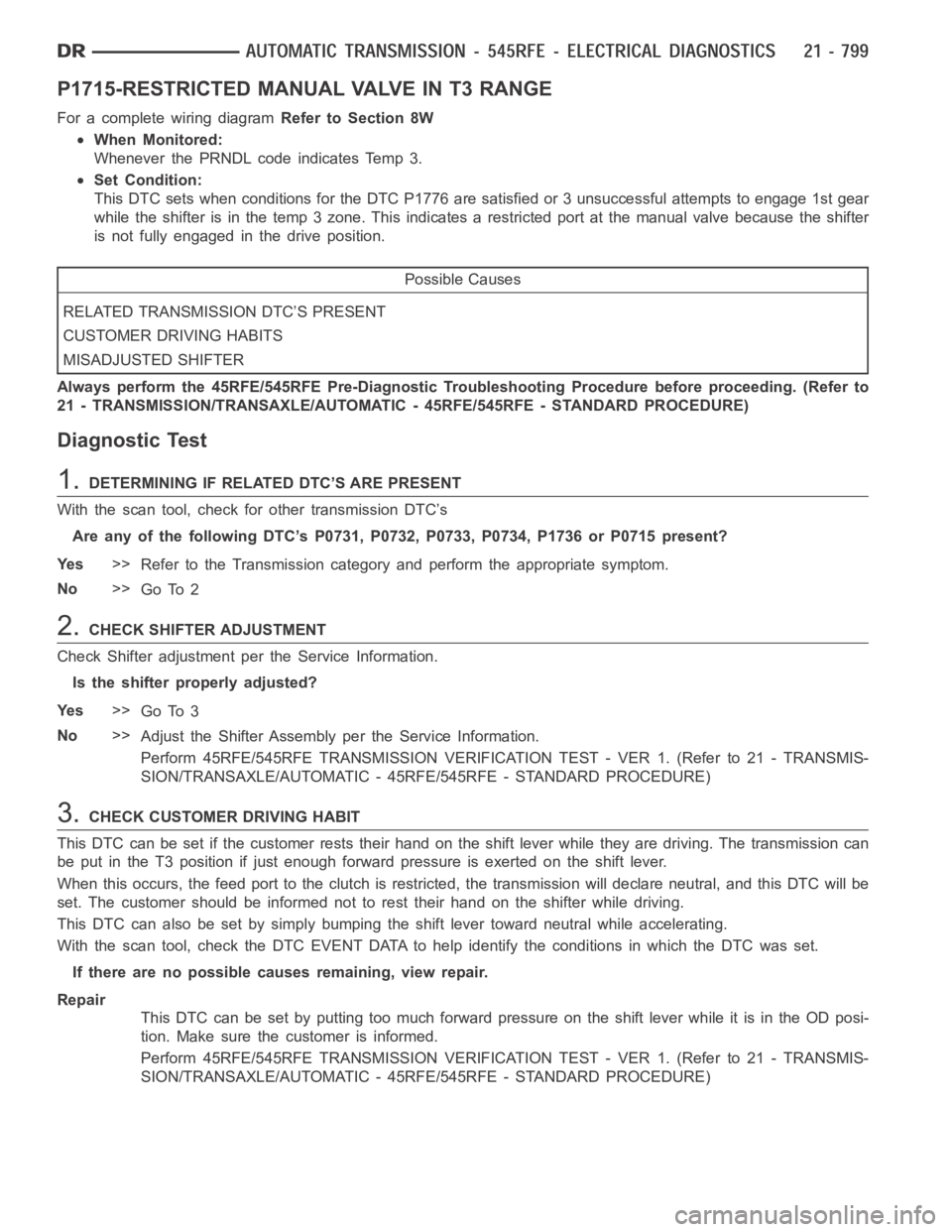
P1715-RESTRICTED MANUAL VALVE IN T3 RANGE
For a complete wiring diagramRefer to Section 8W
When Monitored:
Whenever the PRNDL code indicates Temp 3.
Set Condition:
This DTC sets when conditions for the DTC P1776 are satisfied or 3 unsuccessful attempts to engage 1st gear
while the shifter is in the temp 3 zone. This indicates a restricted port at the manual valve because the shifter
is not fully engaged in the drive position.
Possible Causes
RELATED TRANSMISSION DTC’S PRESENT
CUSTOMER DRIVING HABITS
MISADJUSTED SHIFTER
Always perform the 45RFE/545RFE Pre-Diagnostic Troubleshooting Procedure before proceeding. (Refer to
21 - TRANSMISSION/TRANSAXLE/AUTOMATIC - 45RFE/545RFE - STANDARD PROCEDURE)
Diagnostic Test
1.DETERMINING IF RELATED DTC’S ARE PRESENT
With the scan tool, check for other transmission DTC’s
Are any of the following DTC’s P0731, P0732, P0733, P0734, P1736 or P0715 present?
Ye s>>
Refer to the Transmission category and perform the appropriate symptom.
No>>
Go To 2
2.CHECK SHIFTER ADJUSTMENT
Check Shifter adjustment per the Service Information.
Is the shifter properly adjusted?
Ye s>>
Go To 3
No>>
Adjust the Shifter Assembly per the Service Information.
Perform 45RFE/545RFE TRANSMISSION VERIFICATION TEST - VER 1. (Refer to 21- TRANSMIS-
SION/TRANSAXLE/AUTOMATIC - 45RFE/545RFE - STANDARD PROCEDURE)
3.CHECK CUSTOMER DRIVING HABIT
This DTC can be set if the customer rests their hand on the shift lever while they are driving. The transmission can
be put in the T3 position if just enough forward pressure is exerted on the shift lever.
When this occurs, the feed port to the clutch is restricted, the transmission will declare neutral, and this DTC will be
set. The customer should be informed not to rest their hand on the shifter while driving.
This DTC can also be set by simply bumping the shift lever toward neutral while accelerating.
With the scan tool, check the DTC EVENT DATA to help identify the conditionsin which the DTC was set.
If there are no possible causes remaining, view repair.
Repair
This DTC can be set by putting too much forward pressure on the shift lever while it is in the OD posi-
tion. Make sure the customer is informed.
Perform 45RFE/545RFE TRANSMISSION VERIFICATION TEST - VER 1. (Refer to 21- TRANSMIS-
SION/TRANSAXLE/AUTOMATIC - 45RFE/545RFE - STANDARD PROCEDURE)
Page 3324 of 5267
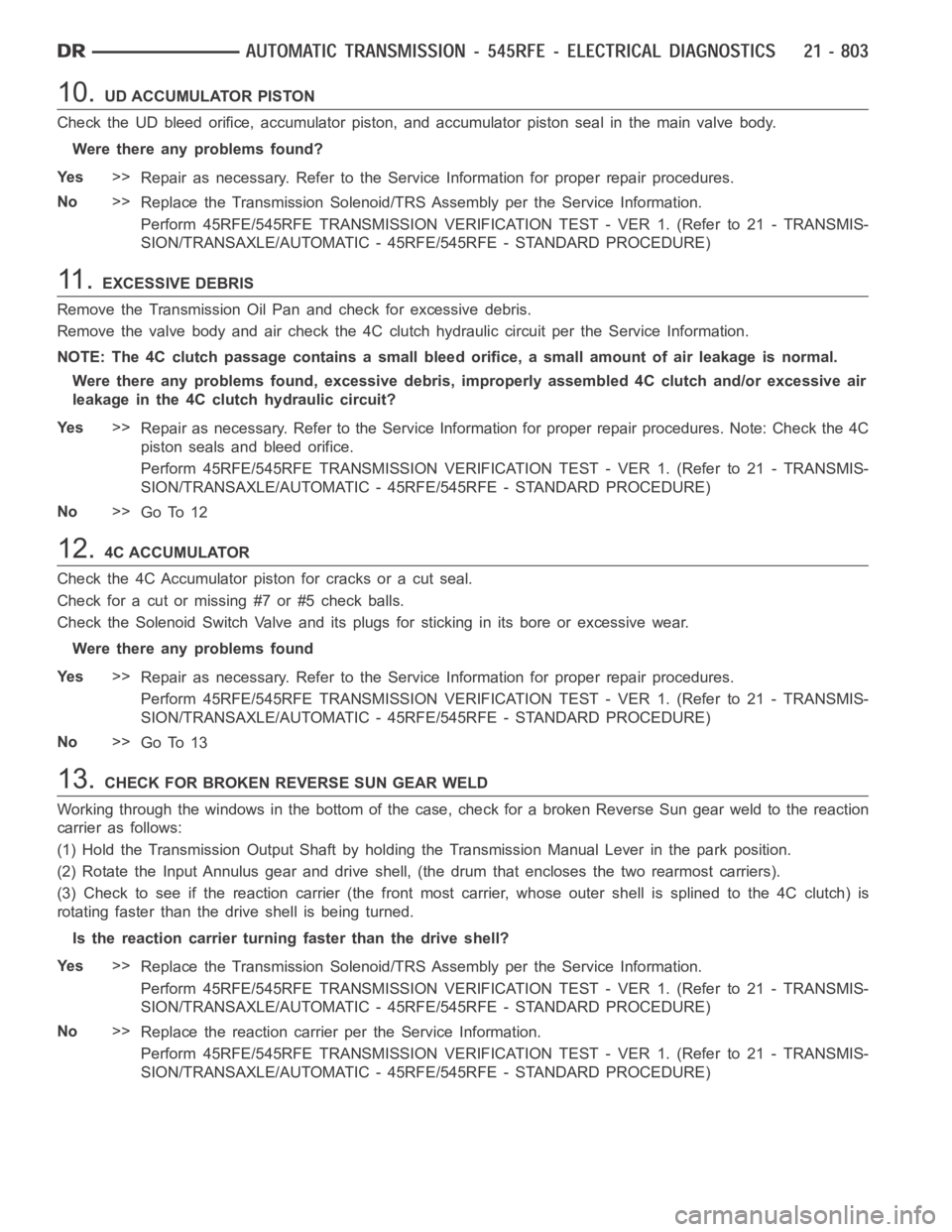
10.UD ACCUMULATOR PISTON
Check the UD bleed orifice, accumulator piston, and accumulator piston seal in the main valve body.
Were there any problems found?
Ye s>>
Repair as necessary. Refer to the Service Information for proper repair procedures.
No>>
Replace the Transmission Solenoid/TRS Assembly per the Service Information.
Perform 45RFE/545RFE TRANSMISSION VERIFICATION TEST - VER 1. (Refer to 21- TRANSMIS-
SION/TRANSAXLE/AUTOMATIC - 45RFE/545RFE - STANDARD PROCEDURE)
11 .EXCESSIVE DEBRIS
Remove the Transmission Oil Pan and check for excessive debris.
Remove the valve body and air check the 4C clutch hydraulic circuit per the Service Information.
NOTE: The 4C clutch passage contains a small bleed orifice, a small amount of air leakage is normal.
Were there any problems found, excessive debris, improperly assembled 4Cclutch and/or excessive air
leakage in the 4C clutch hydraulic circuit?
Ye s>>
Repair as necessary. Refer to the Service Information for proper repair procedures. Note: Check the 4C
piston seals and bleed orifice.
Perform 45RFE/545RFE TRANSMISSION VERIFICATION TEST - VER 1. (Refer to 21- TRANSMIS-
SION/TRANSAXLE/AUTOMATIC - 45RFE/545RFE - STANDARD PROCEDURE)
No>>
Go To 12
12.4C ACCUMULATOR
Check the 4C Accumulator piston for cracks or a cut seal.
Check for a cut or missing #7 or #5 check balls.
Check the Solenoid Switch Valve and its plugs for sticking in its bore or excessive wear.
Were there any problems found
Ye s>>
Repair as necessary. Refer to the Service Information for proper repair procedures.
Perform 45RFE/545RFE TRANSMISSION VERIFICATION TEST - VER 1. (Refer to 21- TRANSMIS-
SION/TRANSAXLE/AUTOMATIC - 45RFE/545RFE - STANDARD PROCEDURE)
No>>
Go To 13
13.CHECK FOR BROKEN REVERSE SUN GEAR WELD
Working through the windows in the bottom of the case, check for a broken Reverse Sun gear weld to the reaction
carrier as follows:
(1) Hold the Transmission Output Shaft by holding the Transmission ManualLever in the park position.
(2) Rotate the Input Annulus gear and drive shell, (the drum that encloses the two rearmost carriers).
(3) Check to see if the reaction carrier (the front most carrier, whose outer shell is splined to the 4C clutch) is
rotating faster than the drive shell is being turned.
Is the reaction carrier turning faster than the drive shell?
Ye s>>
Replace the Transmission Solenoid/TRS Assembly per the Service Information.
Perform 45RFE/545RFE TRANSMISSION VERIFICATION TEST - VER 1. (Refer to 21- TRANSMIS-
SION/TRANSAXLE/AUTOMATIC - 45RFE/545RFE - STANDARD PROCEDURE)
No>>
Replace the reaction carrier per the Service Information.
Perform 45RFE/545RFE TRANSMISSION VERIFICATION TEST - VER 1. (Refer to 21- TRANSMIS-
SION/TRANSAXLE/AUTOMATIC - 45RFE/545RFE - STANDARD PROCEDURE)
Page 3339 of 5267
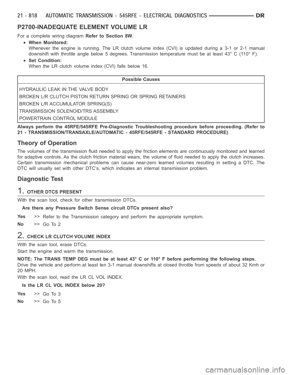
P2700-INADEQUATE ELEMENT VOLUME LR
For a complete wiring diagramRefer to Section 8W.
When Monitored:
Whenever the engine is running. The LR clutch volume index (CVI) is updatedduring a 3-1 or 2-1 manual
downshift with throttle angle below 5 degrees. Transmission temperaturemust be at least 43° C (110° F).
Set Condition:
When the LR clutch volume index (CVI) falls below 16.
Possible Causes
HYDRAULIC LEAK IN THE VALVE BODY
BROKEN L/R CLUTCH PISTON RETURN SPRING OR SPRING RETAINERS
BROKEN L/R ACCUMULATOR SPRING(S)
TRANSMISSION SOLENOID/TRS ASSEMBLY
POWERTRAIN CONTROL MODULE
Always perform the 45RFE/545RFE Pre-Diagnostic Troubleshooting procedure before proceeding. (Refer to
21 - TRANSMISSION/TRANSAXLE/AUTOMATIC - 45RFE/545RFE - STANDARD PROCEDURE)
Theory of Operation
The volumes of the transmission fluid needed to apply the friction elements are continuously monitored and learned
for adaptive controls. As the clutch friction material wears, the volume of fluid needed to apply the clutch increases.
Certain transmission mechanical problems can cause near-zero learned volumes resulting in setting a DTC. The
DTC will usually set with other DTC’s, which indicates an internal transmission problem.
Diagnostic Test
1.OTHER DTCS PRESENT
With the scan tool, check for other transmission DTCs.
Are there any Pressure Switch Sense circuit DTCs present also?
Ye s>>
Refer to the Transmission category and perform the appropriate symptom.
No>>
Go To 2
2.CHECKLRCLUTCHVOLUMEINDEX
With the scan tool, erase DTCs.
Start the engine and warm the transmission.
NOTE: The TRANS TEMP DEG must be at least 43° C or 110° F before performing thefollowing steps.
Drive the vehicle and perform at least ten 3-1 manual downshifts at closed throttle from speeds of about 32 Kmh or
20 MPH.
With the scan tool, read the LR CL VOL INDEX.
Is the LR CL VOL INDEX below 20?
Ye s>>
Go To 3
No>>
Go To 5
Page 3374 of 5267
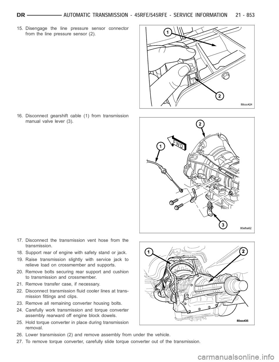
15. Disengage the line pressure sensor connector
from the line pressure sensor (2).
16. Disconnect gearshift cable (1) from transmission
manual valve lever (3).
17. Disconnect the transmission vent hose from the
transmission.
18. Support rear of engine with safety stand or jack.
19. Raise transmission slightly with service jack to
relieve load on crossmember and supports.
20. Remove bolts securing rear support and cushion
to transmission and crossmember.
21. Remove transfer case, if necessary.
22. Disconnect transmission fluid cooler lines at trans-
mission fittings and clips.
23. Remove all remaining converter housing bolts.
24. Carefully work transmission and torque converter
assembly rearward off engine block dowels.
25. Hold torque converter in place during transmission
removal.
26. Lower transmission (2) and remove assembly from under the vehicle.
27. To remove torque converter, carefully slide torque converter out of the transmission.
Page 3375 of 5267

DISASSEMBLY
1. Drain fluid from transmission.
2. Clean exterior of transmission with suitable solvent
or pressure washer.
3. Remove the torque converter from the transmis-
sion.
4. Remove the manual shift lever (1) from the
transmission.
5. Remove the input (3), output (1), and line pressure
sensors (2) from the transmission case.
6. Inspect the ends of the sensors for debris, which
may indicate the nature of the transmission failure.
7. Install Support Stand 8257 (1) onto the transmis-
sion case.
Page 3381 of 5267
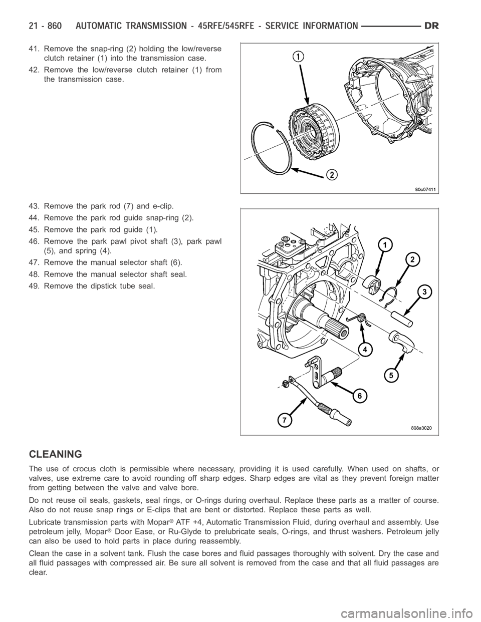
41. Remove the snap-ring (2) holding the low/reverse
clutch retainer (1) into the transmission case.
42. Remove the low/reverse clutch retainer (1) from
the transmission case.
43. Remove the park rod (7) and e-clip.
44. Remove the park rod guide snap-ring (2).
45. Remove the park rod guide (1).
46. Remove the park pawl pivot shaft (3), park pawl
(5), and spring (4).
47. Remove the manual selector shaft (6).
48. Remove the manual selector shaft seal.
49. Remove the dipstick tube seal.
CLEANING
The use of crocus cloth is permissible where necessary, providing it is usedcarefully.Whenusedonshafts,or
valves, use extreme care to avoid rounding off sharp edges. Sharp edges arevital as they prevent foreign matter
from getting between the valve and valve bore.
Do not reuse oil seals, gaskets, seal rings, or O-rings during overhaul. Replace these parts as a matter of course.
Also do not reuse snap rings or E-clips that are bent or distorted. Replace these parts as well.
Lubricate transmission parts with Mopar
ATF +4, Automatic Transmission Fluid, during overhaul and assembly. Use
petroleum jelly, Mopar
Door Ease, or Ru-Glyde to prelubricate seals, O-rings, and thrust washers. Petroleum jelly
canalsobeusedtoholdpartsinplaceduringreassembly.
Clean the case in a solvent tank. Flush the case bores and fluid passages thoroughly with solvent. Dry the case and
all fluid passages with compressed air. Be sure all solvent is removed fromthe case and that all fluid passages are
clear.
Page 3382 of 5267
NOTE: Do not use shop towels or rags to dry the case (or any other transmission component) unless they
aremadefromlint-freematerials.Lintwillsticktocasesurfacesandtransmission components and circu-
late throughout the transmission after assembly. A sufficient quantity of lint can block fluid passages and
interfere with valve body operation.
INSPECTION
Inspect the case for cracks, porous spots, worn bores, or damaged threads.Damaged threads can be repaired with
Helicoil
thread inserts. However, the case will have to be replaced if it exhibits any type of damage or wear.
ASSEMBLY
NOTE: Clean and inspect all components. Replace any components which showevidence of excessive wear
or scoring.
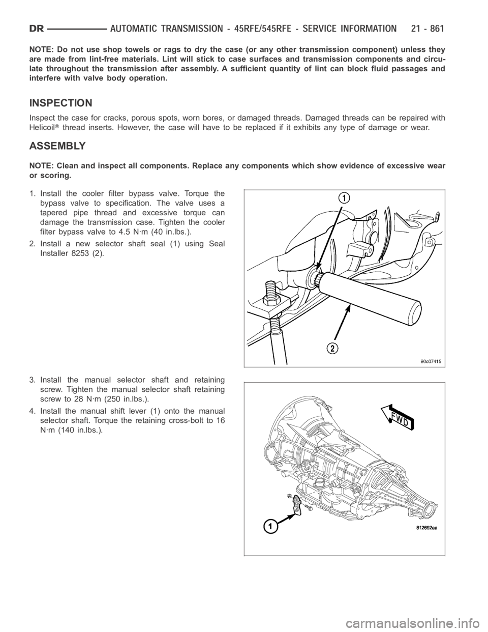
1. Install the cooler filter bypass valve. Torque the
bypass valve to specification. The valve uses a
tapered pipe thread and excessive torque can
damage the transmission case. Tighten the cooler
filter bypass valve to 4.5 Nꞏm (40 in.lbs.).
2. Install a new selector shaft seal (1) using Seal
Installer 8253 (2).
3. Install the manual selector shaft and retaining
screw. Tighten the manual selector shaft retaining
screw to 28 Nꞏm (250 in.lbs.).
4. Install the manual shift lever (1) onto the manual
selector shaft. Torque the retaining cross-bolt to 16
Nꞏm (140 in.lbs.).