Page 3079 of 5267
The valves contained within the valve body (1) include the following :
Regulator valve (8)
Solenoid switch valve (7)
Manual valve (5)
Converter clutch switch valve (6)
Converter clutch control valve (4)
Torque converter regulator valve (2)
Low/Reverse switch valve (3)
In addition, the valve body also contains the thermal valve, #2, 3, 4 & 5 check balls and the 2/4 accumulator assem-
bly.
OPERATION
NOTE: (Refer to 21 - TRANSMISSION/AUTOMATIC - 42RLE - SCHEMATICS AND DIAGRAMS) for a visual aid
in determining valve location, operation and design.
Valve Body - Exploded
1-VALVEBODY
2 - T / C R E G U L AT O R VA LV E
3-L/RSWITCHVALVE
4 - CONVERTER CLUTCH CONTROL VALVE
5 - MANUAL VALVE
6 - CONVERTER CLUTCH SWITCH VALVE
7 - SOLENOID SWITCH VALVE
8 - REGULATOR VALVE
Page 3080 of 5267

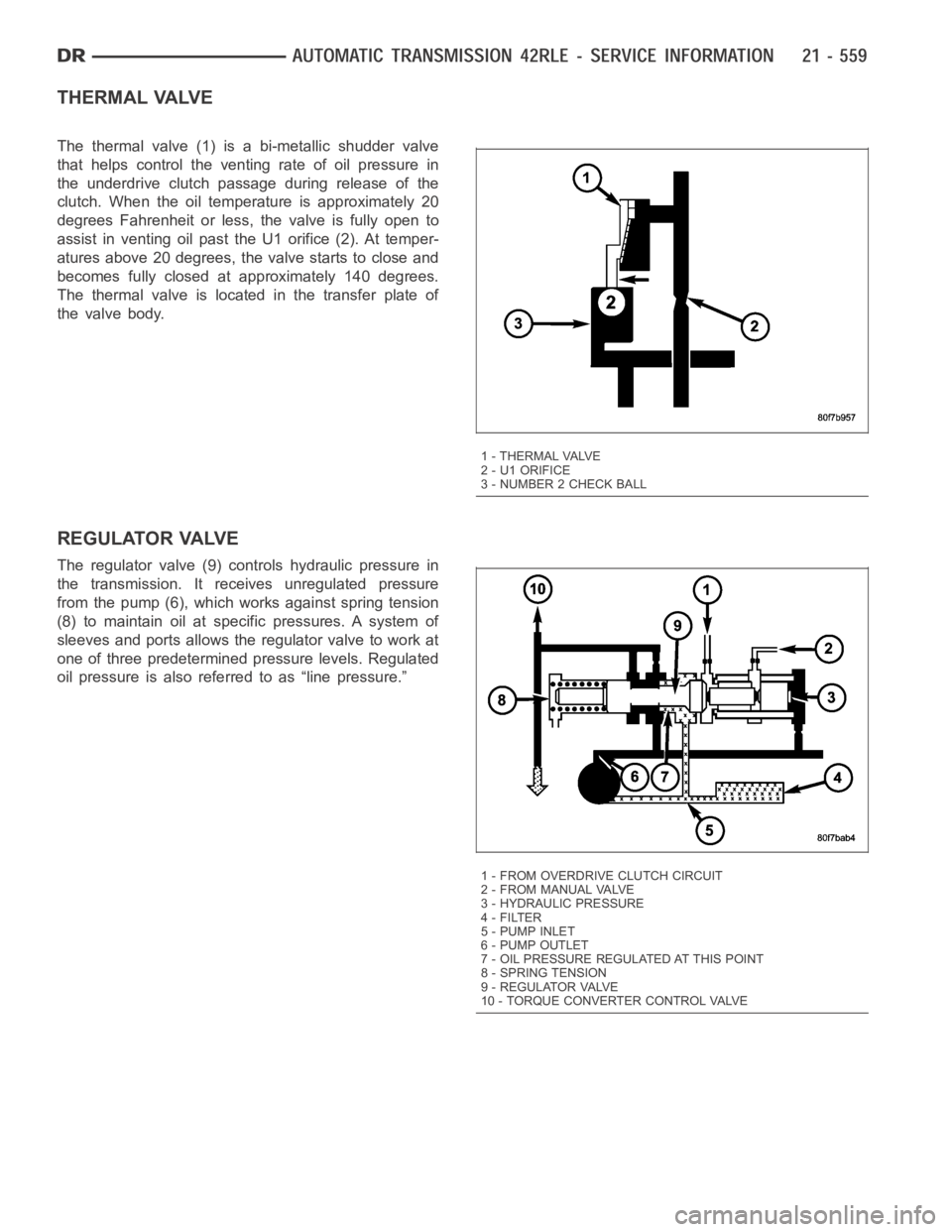
THERMAL VALVE
The thermal valve (1) is a bi-metallic shudder valve
that helps control the venting rate of oil pressure in
the underdrive clutch passage during release of the
clutch. When the oil temperature is approximately 20
degrees Fahrenheit or less, the valve is fully open to
assist in venting oil past the U1 orifice (2). At temper-
atures above 20 degrees, the valve starts to close and
becomes fully closed at approximately 140 degrees.
The thermal valve is located in the transfer plate of
the valve body.
REGULATOR VALVE
The regulator valve (9) controls hydraulic pressure in
the transmission. It receives unregulated pressure
from the pump (6), which works against spring tension
(8) to maintain oil at specific pressures. A system of
sleeves and ports allows the regulator valve to work at
one of three predetermined pressure levels. Regulated
oil pressure is also referred to as “line pressure.”
1 - THERMAL VALVE
2 - U1 ORIFICE
3 - NUMBER 2 CHECK BALL
1 - FROM OVERDRIVE CLUTCH CIRCUIT
2 - FROM MANUAL VALVE
3 - HYDRAULIC PRESSURE
4-FILTER
5-PUMPINLET
6 - PUMP OUTLET
7 - OIL PRESSURE REGULATED AT THIS POINT
8 - SPRING TENSION
9 - REGULATOR VALVE
10 - TORQUE CONVERTER CONTROL VALVE
Page 3083 of 5267

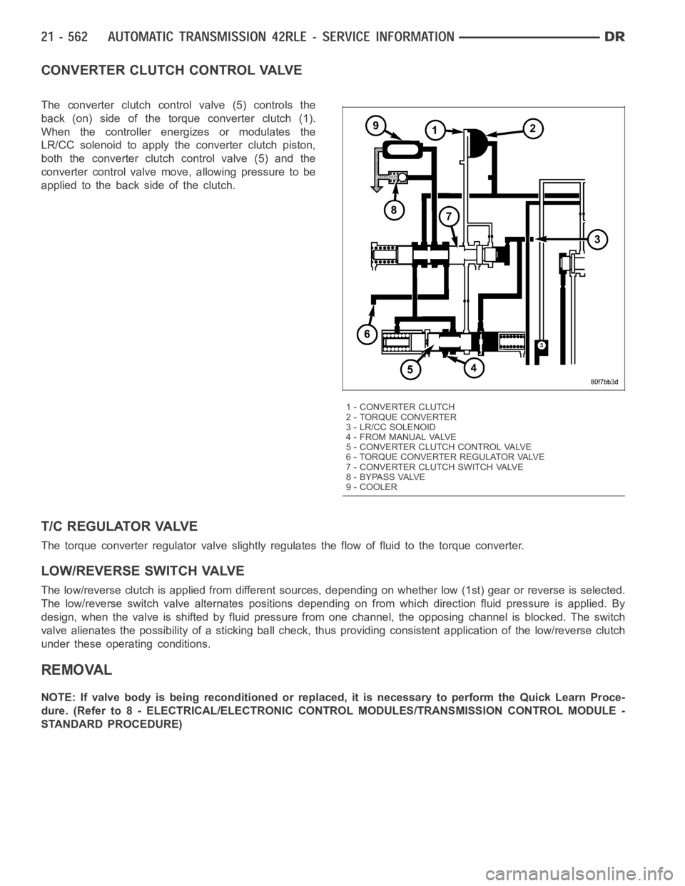
CONVERTER CLUTCH CONTROL VALVE
The converter clutch control valve (5) controls the
back (on) side of the torque converter clutch (1).
When the controller energizes or modulates the
LR/CC solenoid to apply the converter clutch piston,
both the converter clutch control valve (5) and the
converter control valve move, allowing pressure to be
applied to the back side of the clutch.
T/C REGULATOR VALVE
The torque converter regulator valve slightly regulates the flow of fluidto the torque converter.
LOW/REVERSE SWITCH VALVE
The low/reverse clutch is applied from different sources, depending on whether low (1st) gear or reverse is selected.
The low/reverse switch valve alternates positions depending on from which direction fluid pressure is applied. By
design, when the valve is shifted by fluid pressure from one channel, the opposing channel is blocked. The switch
valve alienates the possibility of a sticking ball check, thus providing consistent application of the low/reverse clutch
under these operating conditions.
REMOVAL
NOTE: If valve body is being reconditioned or replaced, it is necessary to perform the Quick Learn Proce-
dure. (Refer to 8 - ELECTRICAL/ELECTRONIC CONTROL MODULES/TRANSMISSIONCONTROL MODULE -
STANDARD PROCEDURE)
1 - CONVERTER CLUTCH
2 - TORQUE CONVERTER
3 - LR/CC SOLENOID
4 - FROM MANUAL VALVE
5 - CONVERTER CLUTCH CONTROL VALVE
6 - TORQUE CONVERTER REGULATOR VALVE
7 - CONVERTER CLUTCH SWITCH VALVE
8 - BYPASS VALVE
9 - COOLER
Page 3084 of 5267
1. Disconnect the transmission range sensor (5) and
solenoid/pressure switchassembly wiring connec-
tors.
2. Disconnect the variable line pressure connector (4),
if equipped.
3. Disconnect the shift cable from the shift lever (at
the transmission).
4. Move the manual shift lever clockwise as far as it
will go. This should be one position past the L posi-
tion. Then remove the manual shift lever.
NOTE: One of the oil pan bolts has a sealing patch
applied from the factory. Separate this bolts for
reuse.
5. Remove transmission pan bolts (2).
6. Remove transmission oil pan (1).
Page 3087 of 5267
8. Remove Transmission Range Sensor (TRS) (1)
and manual shaft (2).
9. Remove Solenoid/Pressure Switch Assembly (1)
from valve body.
10. Remove valve body stiffener plate (1).
Page 3098 of 5267
14. Install the solenoid/pressure switch assembly (1)
and screws to the transfer plate and torque to 5.5
Nꞏm (50 in. lbs.).
15. Install the manual shaft/rooster comb (3) and
transmission range sensor (1) to the valve body.
16. Install the TRS/manual shaft retaining screw (1)
andtorqueto5Nꞏm(45in.lbs.).
17. Install manual shaft seal.
Page 3099 of 5267
18. Install the variable line pressure header onto the
manual shaft (5).
19. Install the shoulder screw (3) to hold the variable
line pressure header (4) to the valve body.
20. Install the pressure control solenoid and line pres-
sure sensor into the valve body.
21. Install the screws (6) to hold the pressure control
solenoid (1) and line pressure sensor (2) to the
valve body.
22. Install the electrical connectors to the pressure
control solenoid (1) and the line pressure sensor
(2).
INSTALLATION
1. Install valve body into position and start bolts (1).
Torque valve body to transmission case bolts (1) to
12 Nꞏm (105 in. lbs.) torque.
2. Install transmission oil filter (1).
Page 3101 of 5267

page page
AUTOMATIC TRANSMISSION - 545RFE -
ELECTRICAL DIAGNOSTICS
DIAGNOSIS AND TESTING
P0122-TPS/APP CIRCUIT LOW............. 582
P0123-TPS/APP CIRCUIT HIGH............. 584
P0124-TPS/APP INTERMITTENT ............ 586
P0218-HIGH TEMPERATURE OPERATION
ACTIVATED............................... 588
P0562-BATTERY VOLTAGE LOW ............ 589
P0602-CONTROL MODULE PROGRAMMING
ERROR/NOT PROGRAMMED............... 594
P0604-INTERNAL CONTROL MODULE RAM . 595
P0605-INTERNAL CONTROL MODULE ROM . 596
P0613-INTERNAL TCM ..................... 597
P0706-TRANSMISSION RANGE SENSOR
RATIONALITY............................. 598
P0711-TRANSMISSION TEMPERATURE
SENSOR PERFORMANCE.................. 602
P0712-TRANSMISSION TEMPERATURE
SENSOR LOW............................. 605
P0713-TRANSMISSION TEMPERATURE
SENSOR HIGH............................ 608
P0714-TRANSMISSION TEMPERATURE
SENSOR INTERMITTENT................... 611
P0715-INPUT SPEED SENSOR 1 CIRCUIT . . . 614
P0720-OUTPUT SPEED SENSOR CIRCUIT . . 620
P0725-ENGINE SPEED SENSOR CIRCUIT . . . 626
P0731-GEAR RATIO ERROR IN 1ST ......... 628
P0732-GEAR RATIO ERROR IN 2ND ........ 631
P0733-GEAR RATIO ERROR IN 3RD ........ 637
P0734-GEAR RATIO ERROR IN 4TH ........ 643
P0735-GEAR RATIO ERROR IN 5TH ........ 647
P0736-GEAR RATIO ERROR IN REVERSE . . . 650
P0740-TCC OUT OF RANGE ................ 653
P0750-LR SOLENOID CIRCUIT............. 655
P0755-2C SOLENOID CIRCUIT............. 659
P0760-OD SOLENOID CIRCUIT ............. 663
P0765-UD SOLENOID CIRCUIT ............. 667
P0770-4C SOLENOID CIRCUIT............. 671
P0841-LR PRESSURE SWITCH
RATIONALITY............................. 675
P0845-2C HYDRAULIC PRESSURE TEST .... 682
P0846-2C PRESSURE SWITCH
RATIONALITY............................. 690
P0868-LINE PRESSURE LOW .............. 697
P0869-LINE PRESSURE HIGH .............. 703
P0870-OD HYDRAULIC PRESSURE TEST . . . 709
P0871-OD PRESSURE SWITCH
RATIONALITY............................. 717
P0875-UD HYDRAULIC PRESSURE TEST . . . 726P0876-UD PRESSURE SWITCH
RATIONALITY............................. 734
P0882-TCM POWER INPUT LOW ........... 741
P0883-TCM POWER INPUT HIGH ........... 745
P0884-POWER UPAT SPEED .............. 749
P0890-SWITCHED BATTERY ............... 751
P0932-LINE PRESSURE SENSOR CIRCUIT . . 755
P0934-LINE PRESSURE SENSOR CIRCUIT
LOW...................................... 758
P0935-LINE PRESSURE SENSOR CIRCUIT
HIGH..................................... 763
P0944-LOSS OF HYDRAULIC PUMP PRIME . 768
P0987-4C HYDRAULIC PRESSURE TEST . . . . 770
P0988-4C PRESSURE SWITCH
RATIONALITY............................. 778
P128B-TCM POWER CONTROL CIRCUIT 2
LOW - TIPM............................... 784
P128C-TCM POWER CONTROL CIRCUIT 2
HIGH - TIPM............................... 787
P128D-TCM POWER CONTROL CIRCUIT 2
OPEN - TIPM.............................. 790
P128E-TCM POWER CONTROL CIRCUIT 2
OVERCURRENT - TIPM.................... 793
P1684-BATTERY WAS DISCONNECTED . . . . . 797
P1715-RESTRICTED MANUAL VALVE IN T3
RANGE................................... 799
P1736-GEAR RATIO ERROR IN 2ND PRIME . 800
P1775-SOLENOID SWITCH VALVE
LATCHED IN TCC POSITION................ 805
P1776-SOLENOID SWITCH VALVE
LATCHED IN LR POSITION................. 809
P1790-FAULT IMMEDIATELY AFTER SHIFT . . 813
P1794-SPEED SENSOR GROUND ERROR . . 814
P2700-INADEQUATE ELEMENT VOLUME LR . 818
P2701-INADEQUATE ELEMENT VOLUME 2C . 820
P2702-INADEQUATE ELEMENT VOLUME
OD....................................... 822
P2703- INADEQUATE ELEMENT VOLUME
UD
........................................ 824
P2704-INADEQUATE ELEMENT VOLUME 4C . 826
P2706-MS SOLENOID CIRCUIT............. 828
U0002-CAN C BUS OFF PERFORMANCE . . . . 832
U0100-NO COMMUNICATION WITH THE
ECM/PCM................................. 834
U0121-LOST COMMUNICATION WITH ABS . . 836
U0141 LOST COMMUNICATION WITH FCM . . 838
STANDARD PROCEDURE
45RFE/545RFE PRE-DIAGNOSTIC
TROUBLESHOOTING PROCEDURE......... 840
45RFE/545RFE TRANSMISSION
VERIFICATION TEST - VER 1............... 841