Page 2124 of 5267
SEAL-OIL-REAR-CRANK AND RETAINER
REMOVAL
1. Remove transmission (Refer to 21 - TRANSMIS-
SION/TRANSAXLE/MANUAL - REMOVAL).
2. Remove clutch and flywheel (Refer to 6 - CLUTCH/
CLUTCH DISC - REMOVAL).
NOTE: The oil seal and retainer are serviced as an
assembly.
3. Remove the seal retainer bolts from cylinder block
and oil pan.
4. Remove the oil seal and retainer (1) assembly.
INSTALLATION
1. Clean the engine block and retainer. Make sure
surfaces are clean and free of oil.
2. Install Special Tool 9060 (1) (seal guide) onto end
of crankshaft. Align hole in tool with dowel pin on
crankshaft.
Page 2125 of 5267
3. Carefully position retainer/oil seal (1) to block.
Tighten the retainer bolts to 11 Nꞏm (95 in. lbs.).
4. Install flywheel and clutch (Refer to 6 - CLUTCH/
CLUTCH DISC - INSTALLATION).
5. Install transmission (Refer to 21 - TRANSMISSION/
TRANSAXLE/MANUAL - INSTALLATION).
Page 2134 of 5267
BEARING-CRANKSHAFT PILOT
REMOVAL
1. Remove transmission (Refer to 21 - TRANSMIS-
SION/TRANSAXLE/MANUAL - REMOVAL).
2. Remove clutch and flywheel (Refer to 6 - CLUTCH/
CLUTCH DISC - REMOVAL).
3. Using Special Tools 8990 (1) and C-3752 (2),
remove pilot bearing from crankshaft.
INSTALLATION
NOTE: New pilot bearing has special grease
packed into bearing. Do not wash grease from
bearing. Install bearing with part number markings
(1) facing out.
Page 2135 of 5267
1. Install pilot bearing with Special Tools 9058 (1) and
C-4171 (2).
2. Install flywheel and clutch (Refer to 6 - CLUTCH/
CLUTCH DISC - INSTALLATION).
3. Install transmission (Refer to 21 - TRANSMISSION/
TRANSAXLE/MANUAL - INSTALLATION).
Page 2414 of 5267

DESCRIPTION - SRT10
The SRT-10 column has noSTARTposition on the key cylinder. The push starter button switch is mounted on the
Instrument panel center stack. All SRT-10 columns are Tilt columns, Standard cab trucks come with manual trans-
missions, Quad cab trucks come equipped with automatic transmissions.
DIAGNOSIS AND TESTING
STEERING COLUMN
If the vehicle is involved in a front end collision/the air bag has deployedthe column must be inspected. This
inspection will determine if the Column has collapsed. Inspect the columnmounting capsules visually and manually
push and pull them to check for separation or fractures. If capsules are fractured or have moved the column MUST
be replaced.
REMOVAL
WARNING: Before servicing the steering column the airbag system must be disarmed. Refer to electrical
restraint system for service procedures. Failure to do so may result in accidental deployment of the airbag
and possible personal injury.
CAUTION: All fasteners must be torqued to specification to ensure proper operation of the steering column.
1. Position the front wheelsstraight ahead.
2. Disconnect the negative (ground) cable from the battery.
3. Remove the airbag, (Refer to 8 - ELECTRICAL/RE-
STRAINTS/DRIVER AIRBAG - REMOVAL).
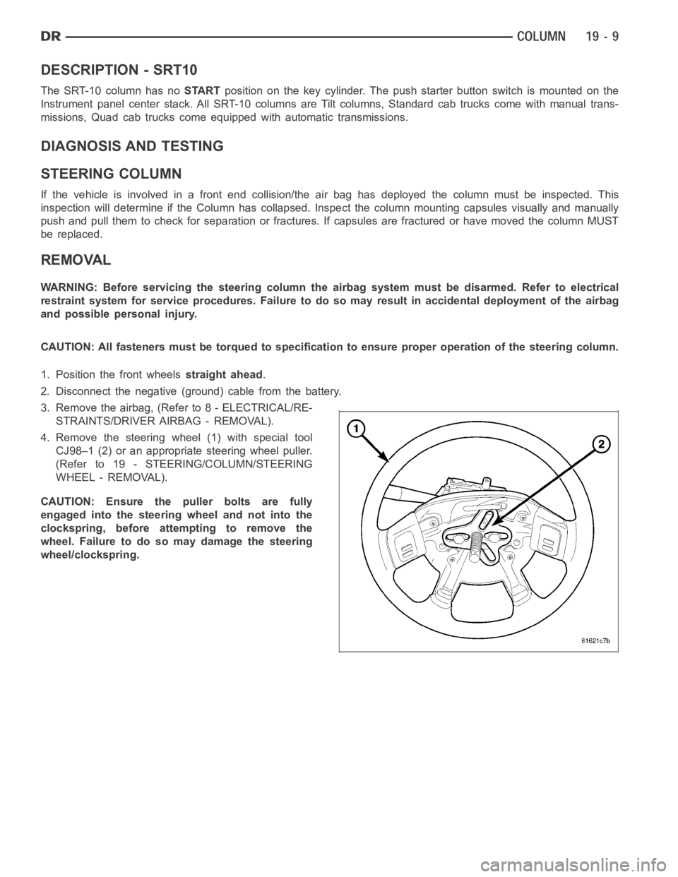
4. Remove the steering wheel (1) with special tool
CJ98–1 (2) or an appropriate steering wheel puller.
(Refer to 19 - STEERING/COLUMN/STEERING
WHEEL - REMOVAL).
CAUTION: Ensure the puller bolts are fully
engaged into the steering wheel and not into the
clockspring, before attempting to remove the
wheel. Failure to do so may damage the steering
wheel/clockspring.
Page 2522 of 5267

TRANSMISSION AND TRANSFER CASE
TABLE OF CONTENTS
page page
MANUAL TRANSMISSION - G56 - SERVICE
INFORMATION...........................1
MANUAL TRANSMISSION - GETRAG 238 -
SERVICE INFORMATION..................70
MANUAL TRANSMISSION-T56 - SERVICE
INFORMATION.........................142
AUTOMATIC TRANSMISSION 42RLE -
ELECTRICAL DIAGNOSTICS..............203
AUTOMATIC TRANSMISSION 42RLE - SERVICE
INFORMATION.........................389
AUTOMATIC TRANSMISSION - 545RFE -
ELECTRICAL DIAGNOSTICS..............580
AUTOMATIC TRANSMISSION - 45RFE/545RFE -
SERVICE INFORMATION.................842
AUTOMATIC TRANSMISSION - 48RE - GAS -
ELECTRICAL DIAGNOSTICS..............987AUTOMATIC TRANSMISSION - 48RE - DIESEL -
ELECTRICAL DIAGNOSTICS.............1105
AUTOMATIC TRANSMISSION - 48RE - SERVICE
INFORMATION........................1266
TRANSFER CASE - ELECTRICAL
DIAGNOSTICS........................1499
TRANSFER CASE - NV241 GENII - SERVICE
INFORMATION........................1563
TRANSFER CASE - NV271 - SERVICE
INFORMATION........................1605
TRANSFER CASE - NV243 - SERVICE
INFORMATION........................1656
TRANSFER CASE - NV244 GENII - SERVICE
INFORMATION........................1700
TRANSFER CASE - NV273 - SERVICE
INFORMATION........................1743
page page
MANUAL TRANSMISSION - G56 - SERVICE
INFORMATION
DIAGNOSIS AND TESTING
MANUAL TRANSMISSION - G56 ............... 2
STANDARD PROCEDURE
DRAIN AND FILL ............................. 3
REMOVAL ..................................... 4
DISASSEMBLY ................................ 8
CLEANING ................................... 28INSPECTION ................................. 28
ASSEMBLY ................................... 29
INSTALLATION ............................... 58
ADJUSTMENTS
MAINSHAFT/COUNTERSHAFT BEARING
PRELOAD.................................. 62
SPECIFICATIONS
MANUAL TRANSMISSION-G56 ............... 65
SPECIAL TOOLS .............................. 67
Page 2523 of 5267

MANUAL TRANSMISSION - G56 - SERVICE INFORMATION
DIAGNOSIS AND TESTING
MANUAL TRANSMISSION - G56
LOW LUBRICANT LEVEL
A low transmission lubricant level is generally the result of a leak, inadequate lubricant fill or incorrect lubricant level
check.
Rear transmission leakswill be from the oil seals or component mating surfaces.
Front transmission leakswill be from the front input shaft retainer seal. Lubricant may drip from theclutchhousing
after extended operation. If leak is severe, it may contaminate the clutchdisc.
Lubricant level checkcan only be made when the vehicle is level and allowing the lubricant to settle for a minute
before checking. This will ensure an accurate check and avoid an under or overfill condition.
HARD SHIFTING
Hard shifting is usually caused by low lubricant level, improper or contaminated lubricants. This will cause noise,
excessive wear, internal bind, and hard shifting. Substantial lubricantleaks can result in gear, shift rail, synchro, and
bearing damage. The first indications of component damage is usually hardshifting and noise.
Shift component damage, clutch adjustment, worn pressure plate or disc are also causes of increased shift effort. If
clutch problem is advanced, gear clash during shifts can result. Worn or damaged synchronizer rings can cause
gear clash when shifting into any forward gear. In some new or rebuilt transmissions, new synchro rings may tend
to stick slightly causing hard or noisy shifts. In most cases, this condition will decline as the rings wear-in.
TRANSMISSION NOISE
Most manual transmissions make some noise during normal operation. Rotating gears generate a mild whine that is
audible, but generally only at extreme speeds.
Severe, highly audible transmission noise is generally the initial indicator of a lubricant problem. Insufficient,
improper or contaminated lubricant will promote rapid wear of gears, synchronizer rings, shift rails, forks and bear-
ings. The overheating caused by a lubricant problem, can also lead to gear and bearing damage.
Page 2586 of 5267
8. Measure the gap (1) between the fixture shaft (2)
and the fixture plunger (3). Repeat measurement
on the opposite side of the countershaft cup and
bearing. The average of the two measurements,
will be the size of the countershaft select shim.
9. Install select shim in front housing countershaft
bearing cup bore and install bearing cup.
SPECIFICATIONS
MANUAL TRANSMISSION-G56
TORQUE SPECIFICATIONS
DESCRIPTION Nꞏm Ft. Lbs. In. Lbs.
Fill Plug 57 42 -
Drain Plug 57 42 -
Front to Rear Housing
Bolts58 43 -
Input Shaft Retainer Bolts 23 17 -
Shift Tower bolts 23 17 -
5-6 Shift Fork Bolts 58 43 -
Shift Rail Support bolts 58 43 -
Reverse Idler Gear Shaft
Bolt58 43 -
P.T.O. Cover Bolts 58 43 -
Clutch Release Pivot Ball 22 16 -