Page 3017 of 5267
CABLE-GEARSHIFT
DIAGNOSIS AND TESTING - GEARSHIFT CABLE
1. Engine starts must be possible with shift lever in PARK or NEUTRAL positions only. Engine starts must not be
possible in any other gear position.
2. With the shift lever in the:
a. PARK position - Apply upward force on the shift arm and remove pressure. Engine starts must be possible.
b. PARK position - Apply downward force on the shift arm and remove pressure. Engine starts must be pos-
sible.
c. NEUTRAL position - Normal position. Engine starts must be possible.
d. NEUTRAL position - Engine running and brakes applied, apply upward forceontheshiftarm.Transmission
shall not be able to shift from neutral to reverse.
REMOVAL
1. Shift transmission into PARK.
2. Raise vehicle.
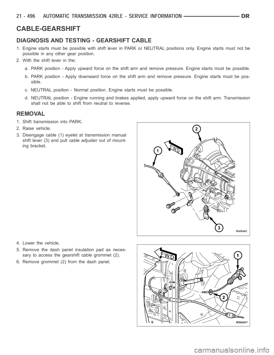
3. Disengage cable (1) eyelet at transmission manual
shift lever (3) and pull cable adjuster out of mount-
ing bracket.
4. Lower the vehicle.
5. Remove the dash panel insulation pad as neces-
sary to access the gearshift cable grommet (2).
6. Remove grommet (2) from the dash panel.
Page 3018 of 5267
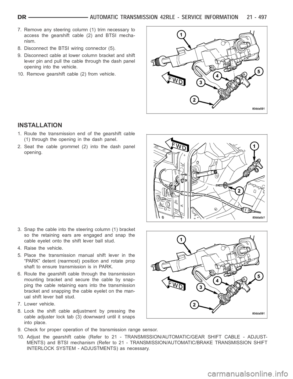
7. Remove any steering column (1) trim necessary to
access the gearshift cable (2) and BTSI mecha-
nism.
8. Disconnect the BTSI wiring connector (5).
9. Disconnect cable at lower column bracket and shift
lever pin and pull the cable through the dash panel
opening into the vehicle.
10. Remove gearshift cable (2) from vehicle.
INSTALLATION
1. Route the transmission end of the gearshift cable
(1) through the opening in the dash panel.
2. Seat the cable grommet (2) into the dash panel
opening.
3. Snap the cable into the steering column (1) bracket
so the retaining ears are engaged and snap the
cable eyelet onto the shift lever ball stud.
4. Raise the vehicle.
5. Place the transmission manual shift lever in the
“PARK” detent (rearmost) position and rotate prop
shaft to ensure transmission is in PARK.
6. Route the gearshift cable through the transmission
mounting bracket and secure the cable by snap-
ping the cable retaining ears into the transmission
bracket and snapping the cable eyelet on the man-
ual shift lever ball stud.
7. Lower vehicle.
8. Lock the shift cable adjustment by pressing the
cable adjuster lock tab (3) downward until it snaps
into place.
9. Check for proper operation of the transmission range sensor.
10. Adjust the gearshift cable (Refer to 21 - TRANSMISSION/AUTOMATIC/GEAR SHIFT CABLE - ADJUST-
MENTS) and BTSI mechanism (Refer to 21 - TRANSMISSION/AUTOMATIC/BRAKE TRANSMISSION SHIFT
INTERLOCK SYSTEM - ADJUSTMENTS) as necessary.
Page 3019 of 5267
ADJUSTMENTS - GEARSHIFT CABLE
Check adjustment by starting the engine in PARK and NEUTRAL. Adjustment isCORRECT if the engine starts only
in these positions. Adjustment is INCORRECT if the engine starts in one butnot both positions. If the engine starts
in any position other than PARK or NEUTRAL, or if the engine will not start atall, the transmission range sensor
may be faulty.
Gearshift Adjustment Procedure
1. Shift transmission into PARK.
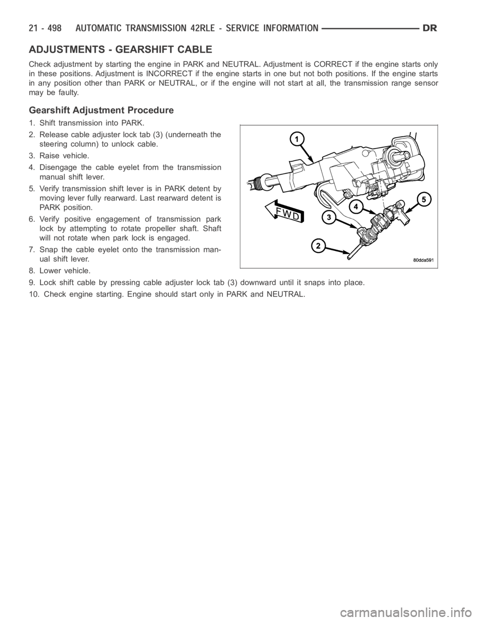
2. Release cable adjuster lock tab (3) (underneath the
steering column) to unlock cable.
3. Raise vehicle.
4. Disengage the cable eyelet from the transmission
manual shift lever.
5. Verify transmission shift lever is in PARK detent by
moving lever fully rearward. Last rearward detent is
PARK position.
6. Verify positive engagement of transmission park
lock by attempting to rotate propeller shaft. Shaft
will not rotate when park lock is engaged.
7. Snap the cable eyelet onto the transmission man-
ual shift lever.
8. Lower vehicle.
9. Lock shift cable by pressing cable adjuster lock tab (3) downward until it snaps into place.
10. Check engine starting. Engine should start only in PARK and NEUTRAL.
Page 3057 of 5267
MECHANISM-SHIFT
DESCRIPTION
The gear shift mechanism provides six shift positions which are:
Park (P)
Reverse (R)
Neutral (N)
Drive (D)
Manual second (2)
Manual low (1)
OPERATION
MANUAL LOW (1) range provides FIRST gear only. Overrun braking is also provided in this range. MANUAL SEC-
OND (2) range provides FIRST and SECOND gear only.
DRIVE range provides FIRST, SECOND, THIRD and OVERDRIVE FOURTH gear ranges. The shift into OVER-
DRIVE FOURTH gear range occurs only after the transmission has completed the shift into D THIRD gear range.
No further movement of the shift mechanism is required to complete the 3-4 shift.
The FOURTH gear upshift occurs automatically when the overdrive selectorswitch is in the ON position. An upshift
to FOURTH gear may not occur or may be delayed in some of the possible shift schedules. (Refer to 8 - ELEC-
TRICAL/ELECTRONIC CONTROL MODULES/TRANSMISSION CONTROL MODULE - OPERATION)
Page 3058 of 5267
SOLENOID
DESCRIPTION
The typical electrical solenoid used in automotive applications is a linear actuator. It is a device that produces
motion in a straight line. This straight line motion can be either forward or backward in direction, and short or long
distance.
A solenoid is an electromechanical device that uses a magnetic force to perform work. It consists of a coil of wire,
wrapped around a magnetic core made from steel or iron, and a spring loaded,movable plunger, which performs
the work, or straight line motion.
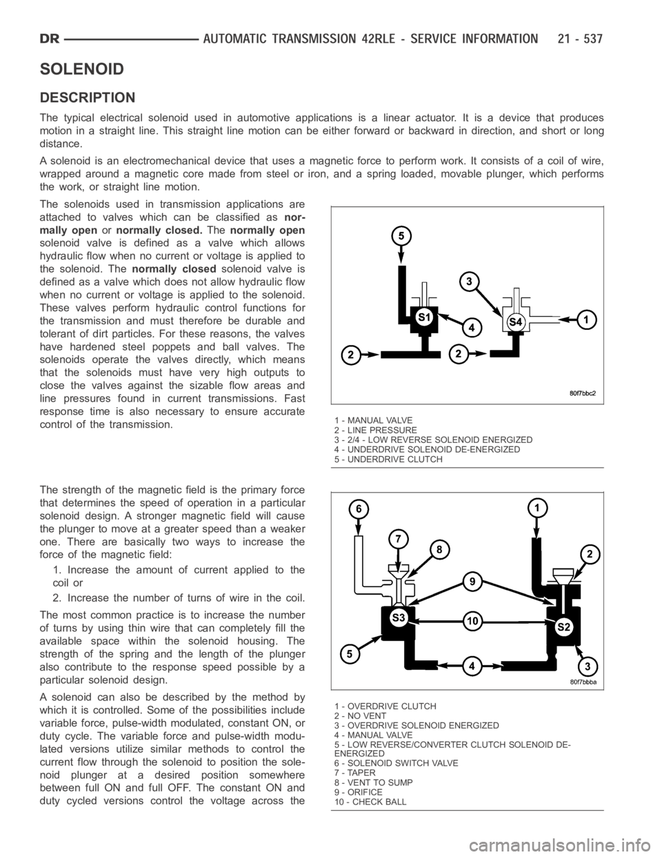
The solenoids used in transmission applications are
attached to valves which can be classified asnor-
mally openornormally closed.Thenormally open
solenoid valve is defined as a valve which allows
hydraulic flow when no current or voltage is applied to
the solenoid. Thenormally closedsolenoid valve is
defined as a valve which does not allow hydraulic flow
when no current or voltage is applied to the solenoid.
These valves perform hydraulic control functions for
the transmission and must therefore be durable and
tolerant of dirt particles. For these reasons, the valves
have hardened steel poppets and ball valves. The
solenoids operate the valves directly, which means
that the solenoids must have very high outputs to
close the valves against the sizable flow areas and
line pressures found in current transmissions. Fast
response time is also necessary to ensure accurate
control of the transmission.
The strength of the magnetic field is the primary force
that determines the speed of operation in a particular
solenoid design. A stronger magnetic field will cause
the plunger to move at a greater speed than a weaker
one. There are basically two ways to increase the
force of the magnetic field:
1. Increase the amount of current applied to the
coil or
2. Increase the number of turns of wire in the coil.
The most common practice is to increase the number
of turns by using thin wire that can completely fill the
available space within the solenoid housing. The
strength of the spring and the length of the plunger
also contribute to the response speed possible by a
particular solenoid design.
A solenoid can also be described by the method by
which it is controlled. Some of the possibilities include
variable force, pulse-width modulated, constant ON, or
duty cycle. The variable force and pulse-width modu-
lated versions utilize similar methods to control the
current flow through the solenoid to position the sole-
noid plunger at a desired position somewhere
between full ON and full OFF. The constant ON and
duty cycled versions control the voltage across the
1 - MANUAL VALVE
2 - LINE PRESSURE
3 - 2/4 - LOW REVERSE SOLENOID ENERGIZED
4 - UNDERDRIVE SOLENOID DE-ENERGIZED
5 - UNDERDRIVE CLUTCH
1-OVERDRIVECLUTCH
2 - NO VENT
3 - OVERDRIVE SOLENOID ENERGIZED
4 - MANUAL VALVE
5 - LOW REVERSE/CONVERTER CLUTCH SOLENOID DE-
ENERGIZED
6-SOLENOIDSWITCHVALVE
7 - TAPER
8 - VENT TO SUMP
9 - ORIFICE
10 - CHECK BALL
Page 3060 of 5267
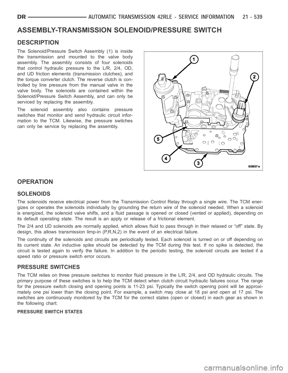
ASSEMBLY-TRANSMISSION SOLENOID/PRESSURE SWITCH
DESCRIPTION
The Solenoid/Pressure Switch Assembly (1) is inside
the transmission and mounted to the valve body
assembly. The assembly consists of four solenoids
that control hydraulic pressure to the L/R, 2/4, OD,
and UD friction elements (transmission clutches), and
the torque converter clutch. The reverse clutch is con-
trolled by line pressure from the manual valve in the
valve body. The solenoids are contained within the
Solenoid/Pressure Switch Assembly, and can only be
serviced by replacing the assembly.
The solenoid assembly also contains pressure
switches that monitor and send hydraulic circuit infor-
mation to the TCM. Likewise, the pressure switches
can only be service by replacing the assembly.
OPERATION
SOLENOIDS
The solenoids receive electrical power from the Transmission Control Relay through a single wire. The TCM ener-
gizes or operates the solenoids individually by grounding the return wireof the solenoid needed. When a solenoid
is energized, the solenoid valve shifts, and a fluid passage is opened or closed (vented or applied), depending on
its default operating state. The result is an apply or release of a frictional element.
The 2/4 and UD solenoids are normally applied, which allows fluid to pass throughintheirrelaxedor“off”state.By
design, this allows transmission limp-in (P,R,N,2) in the event of an electrical failure.
The continuity of the solenoids and circuits are periodically tested. Each solenoid is turned on or off depending on
its current state. An inductive spike should be detected by the TCM during this test. If no spike is detected, the
circuit is tested again to verify the failure. In addition to the periodic testing, the solenoid circuits are tested if a
speed ratio or pressure switch error occurs.
PRESSURE SWITCHES
The TCM relies on three pressure switches to monitor fluid pressure in the L/R, 2/4, and OD hydraulic circuits. The
primary purpose of these switches is to help the TCM detect when clutch circuit hydraulic failures occur. The range
for the pressure switch closing and opening points is 11-23 psi. Typicallythe switch opening point will be approxi-
mately one psi lower than the closing point. For example, a switch may closeat 18 psi and open at 17 psi. The
switches are continuously monitored by the TCM for the correct states (open or closed) in each gear as shown in
the following chart:
PRESSURE SWITCH STATES
Page 3075 of 5267
REMOVAL
1. Remove valve body assembly from vehicle. (Refer
to 21 - TRANSMISSION/AUTOMATIC - 42RLE/
VA LV E B O D Y - R E M O VA L )
2. Remove the manual shaft seal (1).
3. Remove manual shaft/TRS retaining screw (1).
4. Slide TRS off of manual valve shaft.
Page 3076 of 5267
INSTALLATION
1. Install the TRS (2) to the manual shaft. Make sure
TRS locating pin rests in manual valve bore slot.
2. Install the TRS/manual shaft retaining screw (1)
and torque to 5 Nꞏm (45 in. lbs.) torque.
3. Install the manual shaft seal (1).
4. Install valve body to the transmission. (Refer to 21
- TRANSMISSION//AUTOMATIC - 42RLE/VALVE
BODY - INSTALLATION)