2006 DODGE RAM SRT-10 manual transmission
[x] Cancel search: manual transmissionPage 3391 of 5267

49. Install the valve body. Verify that the pin on the
manual lever has properly engaged the TRS
selector plate. Tighten the valve body to transmis-
sion case bolts (1) to 12 Nꞏm (105 in.lbs.).
CAUTION: The primary oil filter seal MUST be fully
installed flush against the oil pump body. DO NOT
install the seal onto the filter neck and attempt to
install the filter and seal as an assembly. Damage
to the transmission will result.
50. Install a new primary oil filter seal in the oil pump
inlet bore. Seat the seal in the bore with the butt
end of a hammer, or other suitable tool.
51. Install the primary oil filter (1) and the oil cooler
return filter (2). Tighten the screw to hold the pri-
mary oil filter to the valve body to 4.5 Nꞏm (40
in.lbs.). Using Filter Wrench 8321, tighten the
cooler return oil filter to the transmission case to
9.5 Nꞏm (7 ft.lbs.).
52. Apply RTV silicone to theoil pan and install the
transmission oil pan. Tighten the bolts to 12 Nꞏm (105 in.lbs.).
53. Install the input (3), output (1), and line pressure
sensors (2). Tighten the bolts to 12 Nꞏm (105
in.lbs.).
Page 3392 of 5267
INSTALLATION
1. Check torque converter hub and hub drive flats for
sharp edges burrs, scratches, or nicks. Polish the
hub and flats with 320/400 grit paper and crocus
cloth if necessary. Verify that the converter hub
o-ring is properly installed and is free of any debris.
The hub must be smooth to avoid damaging pump
seal at installation.
2. If a replacement transmission is being installed,
transfer any components necessary, such as the
manual shift lever and shift cable bracket, from the
original transmission onto the replacement trans-
mission.
3. Lubricate oil pump seal lip with transmission fluid.
4. Align converter and oil pump.
5. Carefully insert converter in oil pump. Then rotate
converter back and forth until fully seated in pump
gears.
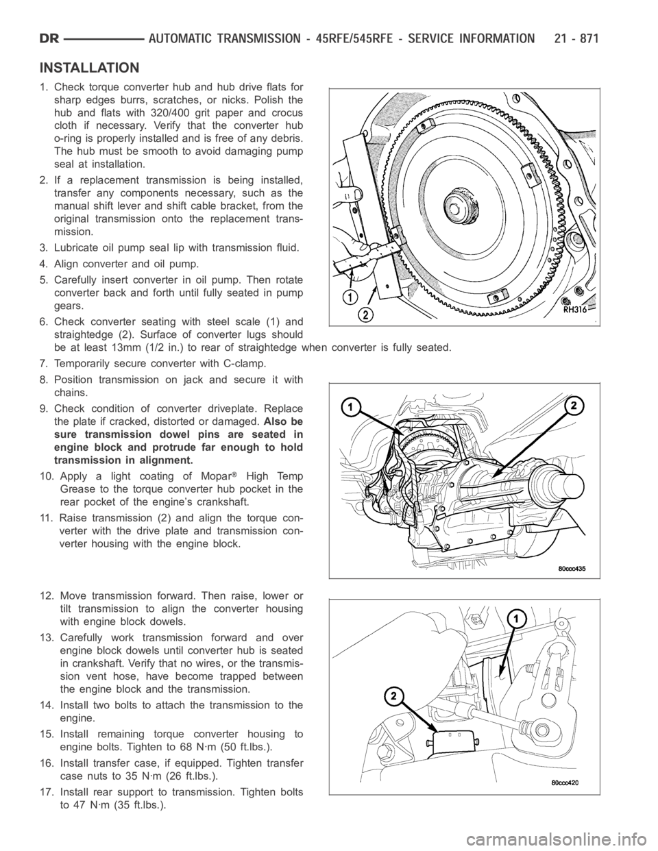
6. Check converter seating with steel scale (1) and
straightedge (2). Surface of converter lugs should
be at least 13mm (1/2 in.) to rear of straightedge when converter is fully seated.
7. Temporarily secure converter with C-clamp.
8. Position transmission on jack and secure it with
chains.
9. Check condition of converter driveplate. Replace
the plate if cracked, distorted or damaged.Also be
sure transmission dowel pins are seated in
engine block and protrude far enough to hold
transmission in alignment.
10. Apply a light coating of Mopar
High Temp
Grease to the torque converter hub pocket in the
rear pocket of the engine’s crankshaft.
11. Raise transmission (2) and align the torque con-
verter with the drive plate and transmission con-
verter housing with the engine block.
12. Move transmission forward. Then raise, lower or
tilt transmission to align the converter housing
with engine block dowels.
13. Carefully work transmission forward and over
engine block dowels until converter hub is seated
in crankshaft. Verify that no wires, or the transmis-
sion vent hose, have become trapped between
theengineblockandthetransmission.
14. Install two bolts to attach the transmission to the
engine.
15. Install remaining torque converter housing to
engine bolts. Tighten to 68 Nꞏm (50 ft.lbs.).
16. Install transfer case, if equipped. Tighten transfer
case nuts to 35 Nꞏm (26 ft.lbs.).
17. Install rear support to transmission. Tighten bolts
to 47 Nꞏm (35 ft.lbs.).
Page 3434 of 5267
CABLE-GEARSHIFT
DIAGNOSIS AND TESTING - GEARSHIFT CABLE
1. Engine starts must be possible with shift lever in PARK or NEUTRAL positions only. Engine starts must not be
possible in any other gear position.
2. With the shift lever in the:
a. PARK position - Apply upward force on the shift arm and remove pressure. Engine starts must be possible.
b. PARK position - Apply downward force on the shift arm and remove pressure. Engine starts must be pos-
sible.
c. NEUTRAL position - Normal position. Engine starts must be possible.
d. NEUTRAL position - Engine running and brakes applied, apply upward forceontheshiftarm.Transmission
shall not be able to shift from neutral to reverse.
REMOVAL
1. Shift transmission into PARK.
2. Raise vehicle.
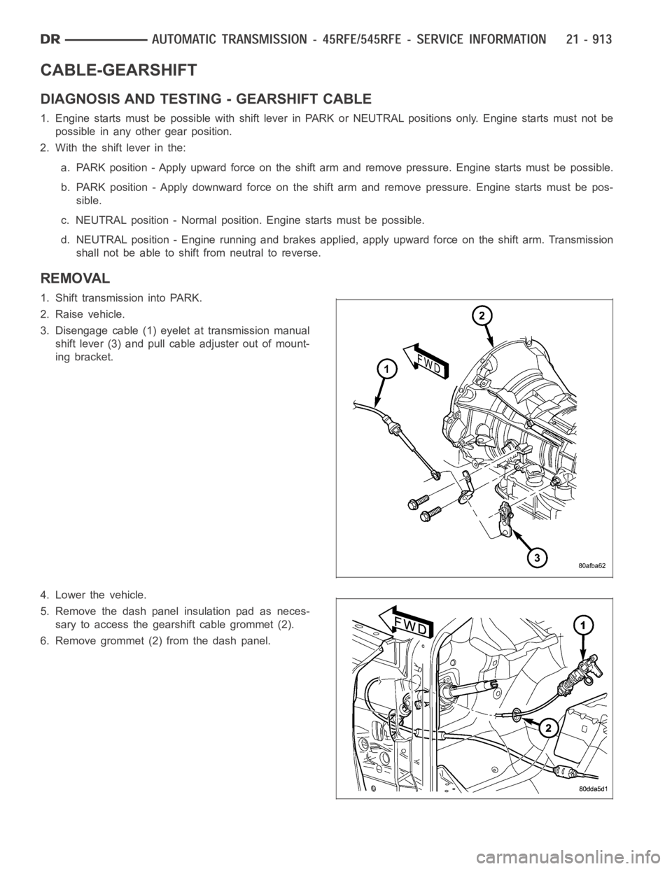
3. Disengage cable (1) eyelet at transmission manual
shift lever (3) and pull cable adjuster out of mount-
ing bracket.
4. Lower the vehicle.
5. Remove the dash panel insulation pad as neces-
sary to access the gearshift cable grommet (2).
6. Remove grommet (2) from the dash panel.
Page 3435 of 5267
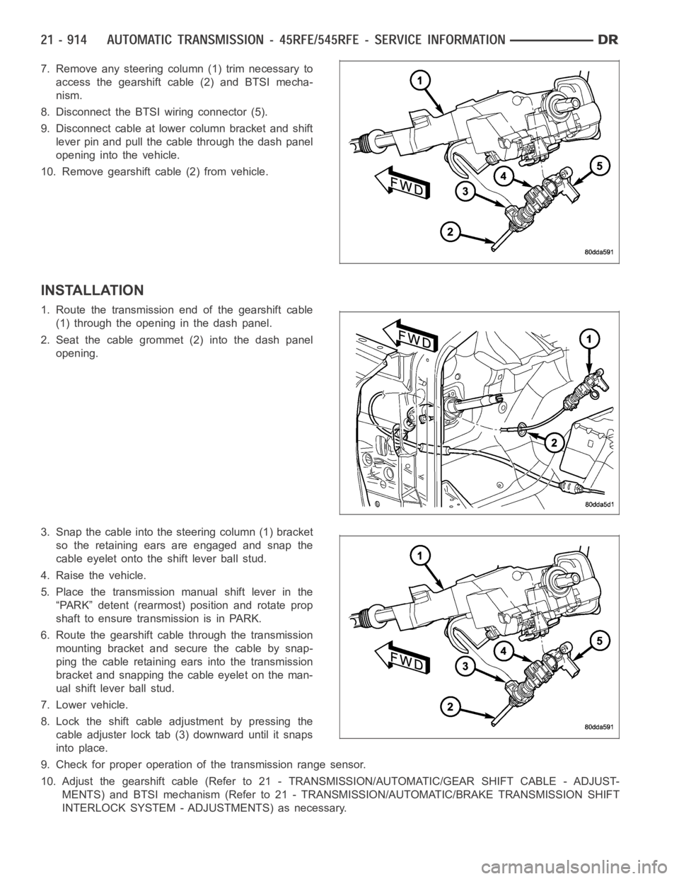
7. Remove any steering column (1) trim necessary to
access the gearshift cable (2) and BTSI mecha-
nism.
8. Disconnect the BTSI wiring connector (5).
9. Disconnect cable at lower column bracket and shift
lever pin and pull the cable through the dash panel
opening into the vehicle.
10. Remove gearshift cable (2) from vehicle.
INSTALLATION
1. Route the transmission end of the gearshift cable
(1) through the opening in the dash panel.
2. Seat the cable grommet (2) into the dash panel
opening.
3. Snap the cable into the steering column (1) bracket
so the retaining ears are engaged and snap the
cable eyelet onto the shift lever ball stud.
4. Raise the vehicle.
5. Place the transmission manual shift lever in the
“PARK” detent (rearmost) position and rotate prop
shaft to ensure transmission is in PARK.
6. Route the gearshift cable through the transmission
mounting bracket and secure the cable by snap-
ping the cable retaining ears into the transmission
bracket and snapping the cable eyelet on the man-
ual shift lever ball stud.
7. Lower vehicle.
8. Lock the shift cable adjustment by pressing the
cable adjuster lock tab (3) downward until it snaps
into place.
9. Check for proper operation of the transmission range sensor.
10. Adjust the gearshift cable (Refer to 21 - TRANSMISSION/AUTOMATIC/GEAR SHIFT CABLE - ADJUST-
MENTS) and BTSI mechanism (Refer to 21 - TRANSMISSION/AUTOMATIC/BRAKE TRANSMISSION SHIFT
INTERLOCK SYSTEM - ADJUSTMENTS) as necessary.
Page 3436 of 5267
ADJUSTMENTS - GEARSHIFT CABLE
Check adjustment by starting the engine in PARK and NEUTRAL. Adjustment isCORRECT if the engine starts only
in these positions. Adjustment is INCORRECT if the engine starts in one butnot both positions. If the engine starts
in any position other than PARK or NEUTRAL, or if the engine will not start atall, the transmission range sensor
may be faulty.
Gearshift Adjustment Procedure
1. Shift transmission into PARK.
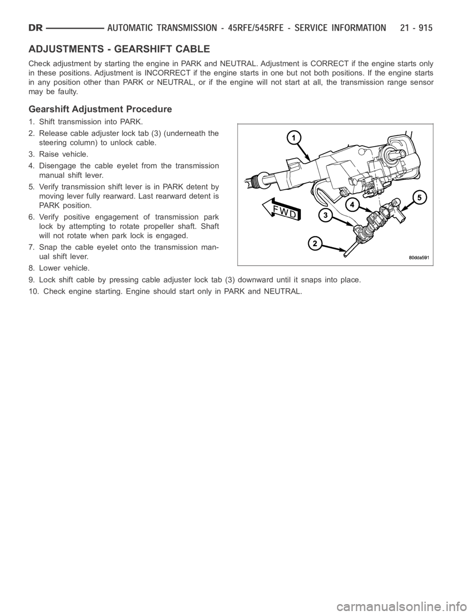
2. Release cable adjuster lock tab (3) (underneath the
steering column) to unlock cable.
3. Raise vehicle.
4. Disengage the cable eyelet from the transmission
manual shift lever.
5. Verify transmission shift lever is in PARK detent by
moving lever fully rearward. Last rearward detent is
PARK position.
6. Verify positive engagement of transmission park
lock by attempting to rotate propeller shaft. Shaft
will not rotate when park lock is engaged.
7. Snap the cable eyelet onto the transmission man-
ual shift lever.
8. Lower vehicle.
9. Lock shift cable by pressing cable adjuster lock tab (3) downward until it snaps into place.
10. Check engine starting. Engine should start only in PARK and NEUTRAL.
Page 3480 of 5267
MECHANISM-SHIFT
DESCRIPTION
The gear shift mechanism provides six shift positions which are:
Park (P)
Reverse (R)
Neutral (N)
Drive (D)
Manual second (2)
Manual low (1)
OPERATION
MANUAL LOW (1) range provides first gear only. Overrun braking is also provided in this range. MANUAL SECOND
(2) range provides first and second gear only.
DRIVE range provides FIRST, SECOND, THIRD, OVERDRIVE FOURTH, and OVERDRIVE FIFTH (if applicable)
gear ranges. The shift into OVERDRIVE FOURTH and FIFTH (if applicable) gear ranges occurs only after the trans-
mission has completed the shift into D THIRD gear range. No further movement of the shift mechanism is required
to complete the 3-4 or 4-5 (if applicable) shifts.
The FOURTH and FIFTH (if applicable) gear upshifts occur automatically when the overdrive selector switch is in
the ON position. No upshift to FOURTH or FIFTH (if applicable) gears will occur if any of the following are true:
The transmission fluid temperature is below 10° C (50° F) or above 121° C (250° F).
The shift to THIRD is not yet complete.
Vehicle speed is too low for the 3-4 or 4-5 (if applicable) shifts to occur.
Upshifts into FOURTH or FIFTH (if applicable) will be delayed when the transmission fluid temperature is below 4.5°
C(40°F)orabove115.5°C(240°F).
Page 3490 of 5267
SENSOR-TRANSMISSION RANGE
DESCRIPTION
The Transmission Range Sensor (TRS) is part of the solenoid module, which is mounted to the top of the valve
body inside the transmission.
The Transmission Range Sensor (TRS) has five switch contact pins that:
Determine shift lever position
Supply ground to the Starter Relay in Park and Neutral only.
Supply +12 V to the backup lamps in Reverse only.
The TRS also has an integrated temperature sensor (thermistor) that communicates transmission temperature to the
TCM and PCM.
OPERATION
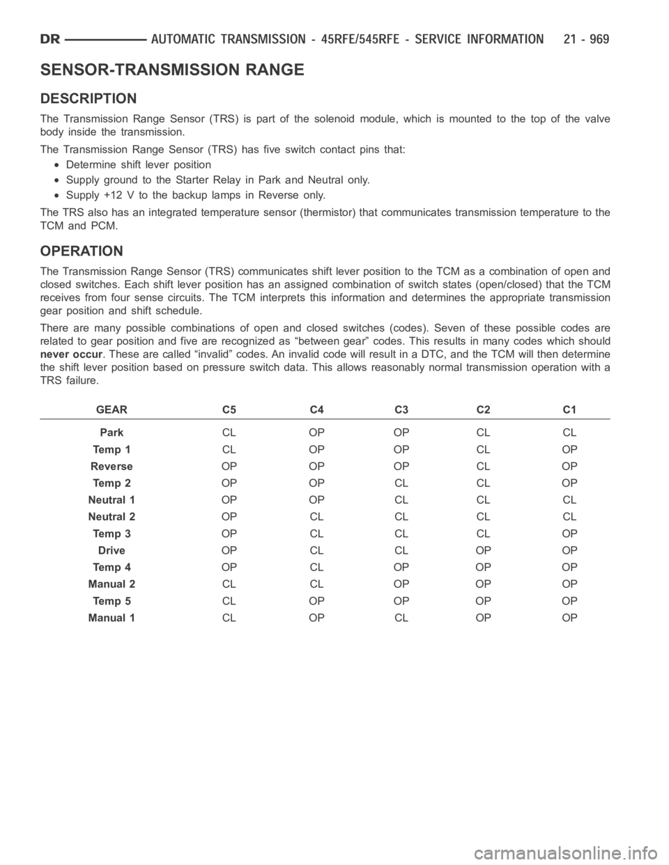
The Transmission Range Sensor (TRS) communicates shift lever position tothe TCM as a combination of open and
closed switches. Each shift lever position has an assigned combination ofswitch states (open/closed) that the TCM
receives from four sense circuits. The TCM interprets this information and determines the appropriate transmission
gear position and shift schedule.
There are many possible combinations of open and closed switches (codes).Seven of these possible codes are
related to gear position and five are recognized as “between gear” codes. This results in many codes which should
never occur. These are called “invalid” codes. An invalid code will result in a DTC, andthe TCM will then determine
the shift lever position based on pressure switch data. This allows reasonably normal transmission operation with a
TRS failure.
GEAR C5 C4 C3 C2 C1
ParkCL OP OP CL CL
Te m p 1CL OP OP CL OP
ReverseOP OP OP CL OP
Te m p 2OP OP CL CL OP
Neutral 1OP OP CL CL CL
Neutral 2OP CL CL CL CL
Te m p 3OP CL CL CL OP
DriveOP CL CL OP OP
Te m p 4OP CL OP OP OP
Manual 2CL CL OP OP OP
Te m p 5CL OP OP OP OP
Manual 1CL OP CL OP OP
Page 3491 of 5267
ASSEMBLY-TRANSMISSION SOLENOID/TRS
DESCRIPTION
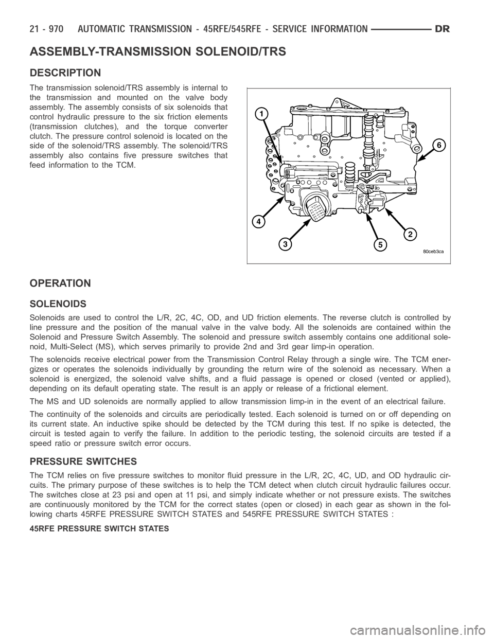
The transmission solenoid/TRS assembly is internal to
the transmission and mounted on the valve body
assembly. The assembly consists of six solenoids that
control hydraulic pressure to the six friction elements
(transmission clutches), and the torque converter
clutch. The pressure control solenoid is located on the
side of the solenoid/TRS assembly. The solenoid/TRS
assembly also contains five pressure switches that
feed information to the TCM.
OPERATION
SOLENOIDS
Solenoids are used to control the L/R, 2C, 4C, OD, and UD friction elements.The reverse clutch is controlled by
line pressure and the position of the manual valve in the valve body. All thesolenoids are contained within the
Solenoid and Pressure Switch Assembly. The solenoid and pressure switch assembly contains one additional sole-
noid, Multi-Select (MS), which serves primarily to provide 2nd and 3rd gear limp-in operation.
The solenoids receive electrical power from the Transmission Control Relay through a single wire. The TCM ener-
gizes or operates the solenoids individually by grounding the return wireof the solenoid as necessary. When a
solenoid is energized, the solenoid valve shifts, and a fluid passage is opened or closed (vented or applied),
depending on its default operating state. The result is an apply or releaseof a frictional element.
The MS and UD solenoids are normallyapplied to allow transmission limp-inin the event of an electrical failure.
The continuity of the solenoids and circuits are periodically tested. Each solenoid is turned on or off depending on
its current state. An inductive spike should be detected by the TCM during this test. If no spike is detected, the
circuit is tested again to verify the failure. In addition to the periodic testing, the solenoid circuits are tested if a
speed ratio or pressure switch error occurs.
PRESSURE SWITCHES
The TCM relies on five pressure switches to monitor fluid pressure in the L/R, 2C, 4C, UD, and OD hydraulic cir-
cuits. The primary purpose of these switches is to help the TCM detect when clutch circuit hydraulic failures occur.
The switches close at 23 psi and open at 11 psi, and simply indicate whether or not pressure exists. The switches
are continuously monitored by the TCM for the correct states (open or closed) in each gear as shown in the fol-
lowing charts 45RFE PRESSURE SWITCH STATES and 545RFE PRESSURE SWITCH STATES :
45RFE PRESSURE SWITCH STATES