Page 3966 of 5267
6. If necessary, loosen the TRS mounting bracket (2)
in the transmission case using Adapter 8581 (3).
7. If necessary, remove the TRS mounting bracket (2)
from the transmission case.
INSTALLATION
1. Move the transmission manual shaft lever to the
manual LOW position.
2. If necessary, install the TRS mounting bracket (2)
into the transmission case. Using Adapter 8581 (3),
tighten the mounting bracket to 34 Nꞏm (300
in.lbs.).
Page 3967 of 5267
3. Install the TRS (3) into the mounting bracket (2)
with the wiring connector facing the front of the
transmission.
4. Install the two screws to hold the TRS to the
mounting bracket. Tighten the screws to 5 Nꞏm (45
in.lbs.).
5. Verify proper sensor operation (1-4).
6. Move the transmission manual shaft lever to the
PARK position.
7. Connect TRS wiring connector to the TRS and
lower vehicle.
8. Refill the transmission fluid to the correct level.
1 - NEUTRAL CONTACT
2 - MANUAL LEVER AND SENSOR PLUNGER IN REVERSE
POSITION
3 - PARK CONTACT
4 - TRANSMISSION RANGE SENSOR
Page 3969 of 5267
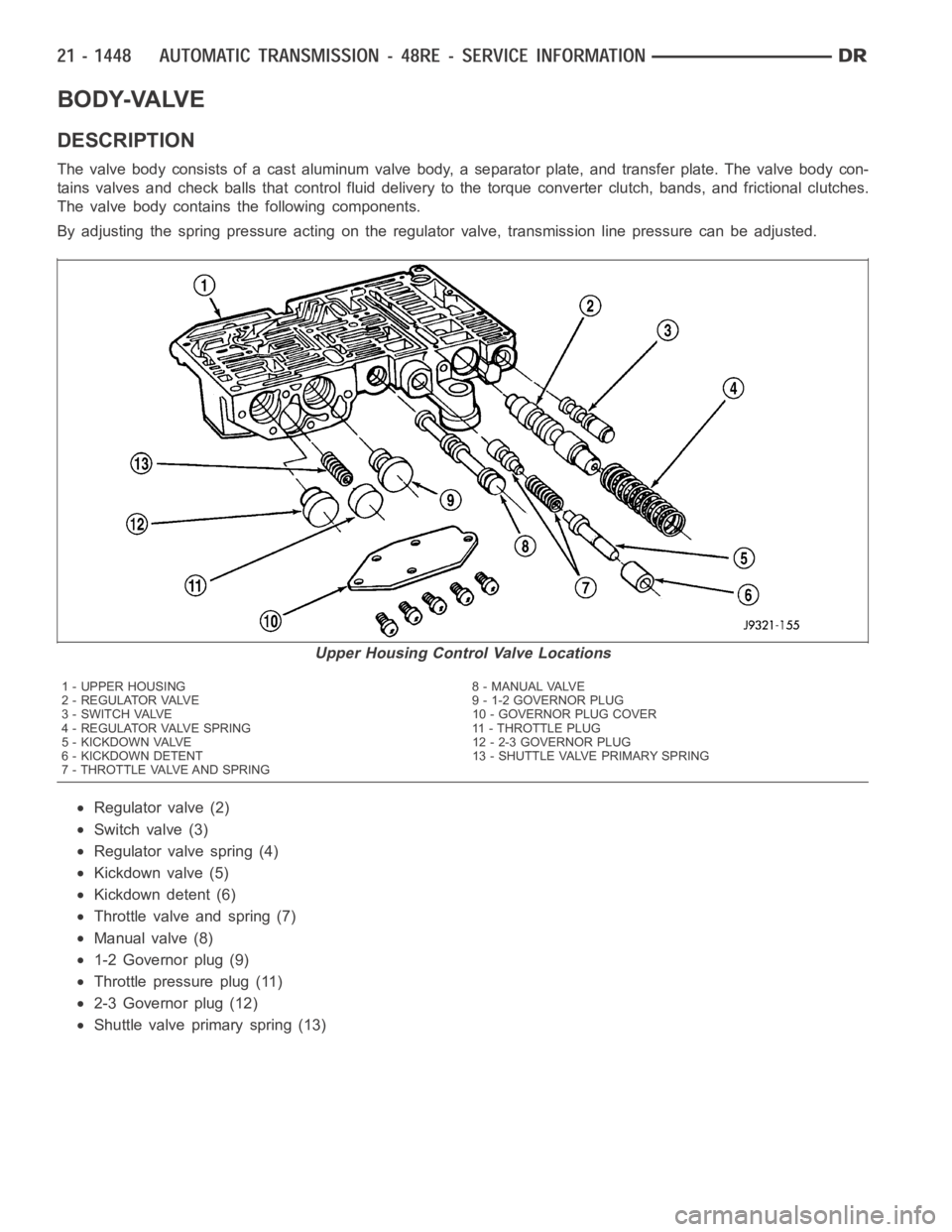
BODY-VALVE
DESCRIPTION
The valve body consists of a cast aluminum valve body, a separator plate, and transfer plate. The valve body con-
tains valves and check balls that control fluid delivery to the torque converter clutch, bands, and frictional clutches.
The valve body contains the following components.
By adjusting the spring pressure acting on the regulator valve, transmission line pressure can be adjusted.
Regulator valve (2)
Switch valve (3)
Regulator valve spring (4)
Kickdown valve (5)
Kickdown detent (6)
Throttle valve and spring (7)
Manual valve (8)
1-2 Governor plug (9)
Throttlepressureplug(11)
2-3 Governor plug (12)
Shuttle valve primary spring (13)
Upper Housing Control Valve Locations
1 - UPPER HOUSING 8 - MANUAL VALVE
2 - REGULATOR VALVE 9 - 1-2 GOVERNOR PLUG
3 - SWITCH VALVE 10 - GOVERNOR PLUG COVER
4 - REGULATOR VALVE SPRING 11 - THROTTLE PLUG
5 - KICKDOWN VALVE 12 - 2-3 GOVERNOR PLUG
6 - KICKDOWN DETENT 13 - SHUTTLE VALVE PRIMARY SPRING
7 - THROTTLE VALVE AND SPRING
Page 3980 of 5267
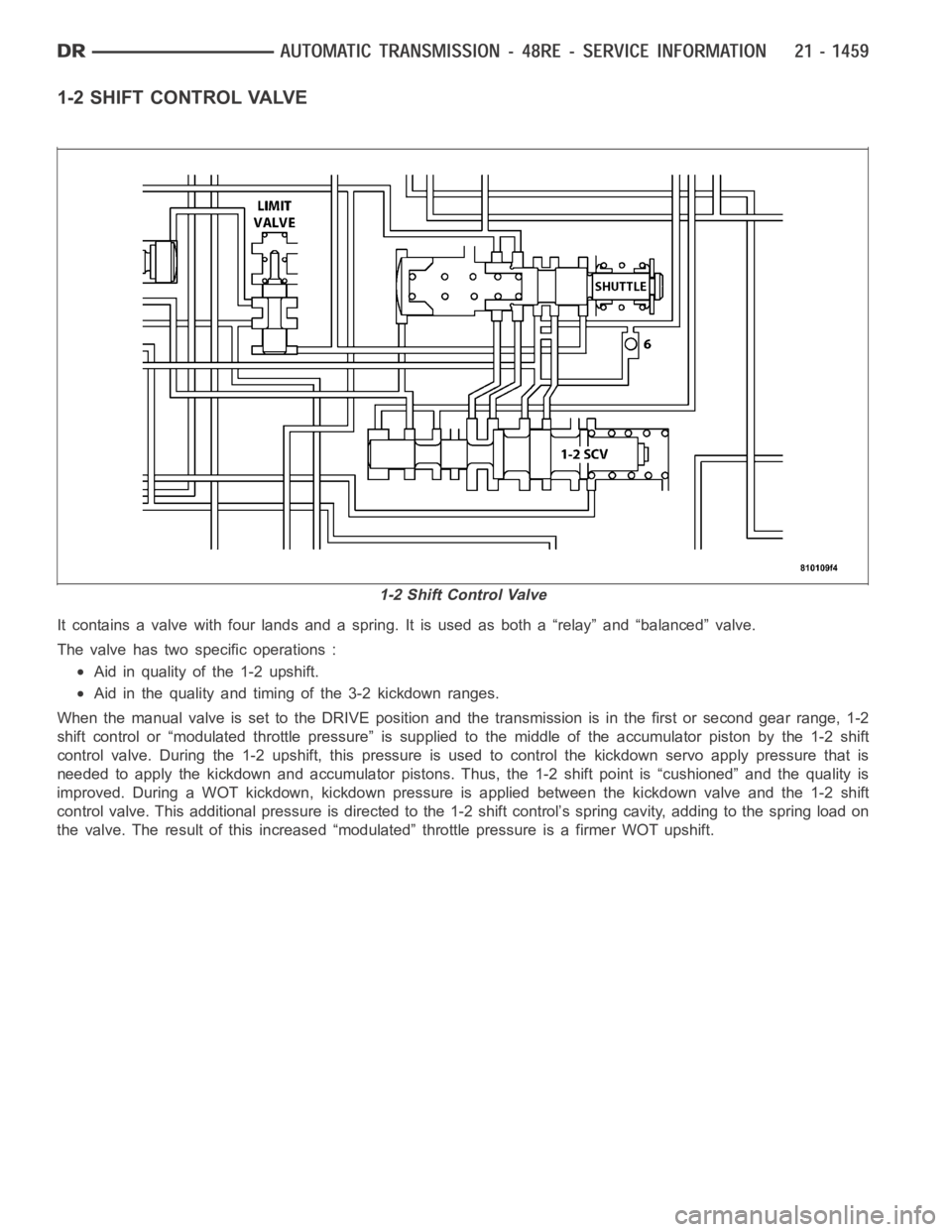
1-2 SHIFT CONTROL VALVE
It contains a valve with four lands and a spring. It is used as both a “relay” and “balanced” valve.
The valve has two specific operations :
Aid in quality of the 1-2 upshift.
Aid in the quality and timing of the 3-2 kickdown ranges.
When the manual valve is set to the DRIVE position and the transmission is inthe first or second gear range, 1-2
shift control or “modulated throttle pressure” is supplied to the middle of the accumulator piston by the 1-2 shift
control valve. During the 1-2 upshift, this pressure is used to control thekickdown servo apply pressure that is
needed to apply the kickdown and accumulator pistons. Thus, the 1-2 shift point is “cushioned” and the quality is
improved. During a WOT kickdown, kickdown pressure is applied between thekickdown valve and the 1-2 shift
control valve. This additional pressure is directed to the 1-2 shift control’s spring cavity, adding to the spring load on
the valve. The result of this increased “modulated” throttle pressure is afirmer WOT upshift.
1-2 Shift Control Valve
Page 3991 of 5267
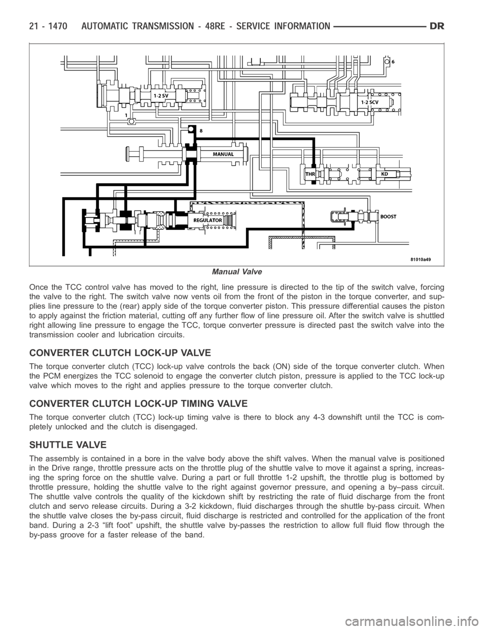
Once the TCC control valve has moved to the right, line pressure is directedto the tip of the switch valve, forcing
the valve to the right. The switch valve now vents oil from the front of the piston in the torque converter, and sup-
plies line pressure to the (rear) apply side of the torque converter piston. This pressure differential causes the piston
to apply against the friction material, cutting off any further flow of line pressure oil. After the switch valve is shuttled
right allowing line pressure to engage the TCC, torque converter pressureis directed past the switch valve into the
transmission cooler and lubrication circuits.
CONVERTER CLUTCH LOCK-UP VALVE
The torque converter clutch (TCC) lock-up valve controls the back (ON) side of the torque converter clutch. When
the PCM energizes the TCC solenoid to engage the converter clutch piston, pressure is applied to the TCC lock-up
valve which moves to the right and applies pressure to the torque converterclutch.
CONVERTER CLUTCH LOCK-UP TIMING VALVE
The torque converter clutch (TCC) lock-up timing valve is there to block any 4-3 downshift until the TCC is com-
pletely unlocked and the clutch is disengaged.
SHUTTLE VALVE
The assembly is contained in a bore in the valve body above the shift valves.When the manual valve is positioned
in the Drive range, throttle pressure acts on the throttle plug of the shuttle valve to move it against a spring, increas-
ing the spring force on the shuttle valve. During a part or full throttle 1-2upshift, the throttle plug is bottomed by
throttle pressure, holding the shuttle valve to the right against governor pressure, and opening a by–pass circuit.
The shuttle valve controls the quality of the kickdown shift by restricting the rate of fluid discharge from the front
clutch and servo release circuits. During a 3-2 kickdown, fluid discharges through the shuttle by-pass circuit. When
the shuttle valve closes the by-pass circuit, fluid discharge is restricted and controlled for the application of the front
band. During a 2-3 “lift foot” upshift, the shuttle valve by-passes the restriction to allow full fluid flow through the
by-pass groove for a faster release of the band.
Manual Valve
Page 3992 of 5267
BOOST VALVE
The boost valve provides increased fluid apply pres-
sure to the overdrive clutch during 3-4 upshifts, and
when accelerating in fourth gear.
Theboostvalvealsoservestoincreaselinepressure
during torque converter lock-up.
REMOVAL
The valve body can be removed for service without having to remove the transmission assembly.
The valve body can be disassembled for cleaning and inspection of the individual components.
The only replaceable valve body components are:
Manual lever.
Manual lever washer, seal, E-clip, and shaft seal.
Boost Valve Before Lock-up
Boost Valve After Lock-up
Page 3993 of 5267
Manual lever detent ball.
Throttle lever.
Fluid filter.
Pressure adjusting screw bracket.
Governor pressure solenoid.
Governor pressure sensor (includes transmission temperature thermistor).
Converter clutch/overdrive solenoid assembly and harness.
Governor housing gasket.
Solenoid case connector O-rings.
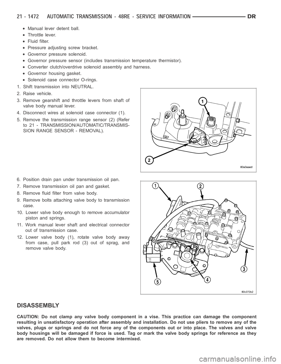
1. Shift transmission into NEUTRAL.
2. Raise vehicle.
3. Remove gearshift and throttle levers from shaft of
valve body manual lever.
4. Disconnect wires at solenoid case connector (1).
5. Remove the transmission range sensor (2) (Refer
to 21 - TRANSMISSION/AUTOMATIC/TRANSMIS-
SION RANGE SENSOR - REMOVAL).
6. Position drain pan under transmission oil pan.
7. Remove transmission oil pan and gasket.
8. Remove fluid filter from valve body.
9. Remove bolts attaching valve body to transmission
case.
10. Lower valve body enough to remove accumulator
piston and springs.
11. Work manual lever shaft and electrical connector
out of transmission case.
12. Lower valve body (1), rotate valve body away
from case, pull park rod (3) out of sprag, and
remove valve body.
DISASSEMBLY
CAUTION: Do not clamp any valve body component in a vise. This practice can damage the component
resulting in unsatisfactory operation after assembly and installation.Do not use pliers to remove any of the
valves, plugs or springs and do not force any of the components out or into place. The valves and valve
body housings will be damaged if force is used. Tag or mark the valve body springs for reference as they
are removed. Do not allow them to become intermixed.
Page 4017 of 5267
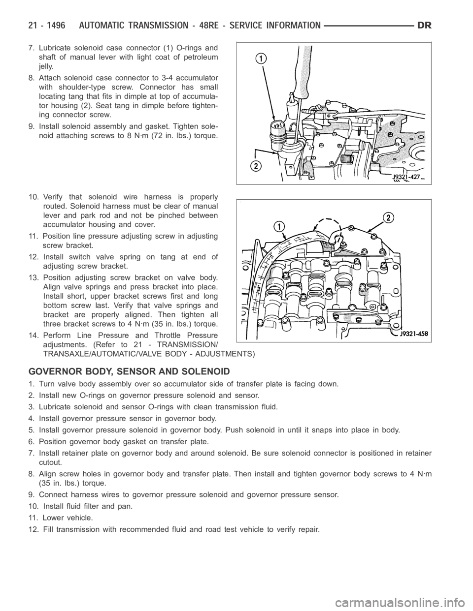
7. Lubricate solenoid case connector (1) O-rings and
shaft of manual lever with light coat of petroleum
jelly.
8. Attach solenoid case connector to 3-4 accumulator
with shoulder-type screw. Connector has small
locating tang that fits indimple at top of accumula-
tor housing (2). Seat tang in dimple before tighten-
ing connector screw.
9. Install solenoid assembly and gasket. Tighten sole-
noid attaching screws to 8 Nꞏm (72 in. lbs.) torque.
10. Verify that solenoid wire harness is properly
routed. Solenoid harness must be clear of manual
lever and park rod and not be pinched between
accumulator housing and cover.
11. Position line pressure adjusting screw in adjusting
screw bracket.
12. Install switch valve spring on tang at end of
adjusting screw bracket.
13. Position adjusting screw bracket on valve body.
Align valve springs and press bracket into place.
Install short, upper bracket screws first and long
bottom screw last. Verify that valve springs and
bracket are properly aligned. Then tighten all
three bracket screws to 4 Nꞏm (35 in. lbs.) torque.
14. Perform Line Pressure and Throttle Pressure
adjustments. (Refer to 21 - TRANSMISSION/
TRANSAXLE/AUTOMATIC/VALVE BODY - ADJUSTMENTS)
GOVERNOR BODY, SENSOR AND SOLENOID
1. Turn valve body assembly over so accumulator side of transfer plate is facing down.
2. Install new O-rings on governor pressure solenoid and sensor.
3. Lubricate solenoid and sensor O-rings with clean transmission fluid.
4. Install governor pressure sensor in governor body.
5. Install governor pressure solenoid in governor body. Push solenoid in until it snaps into place in body.
6. Position governor body gasket on transfer plate.
7. Install retainer plate on governor body and around solenoid. Be sure solenoid connector is positioned in retainer
cutout.
8. Align screw holes in governor body and transfer plate. Then install and tighten governor body screws to 4 Nꞏm
(35 in. lbs.) torque.
9. Connect harness wires to governor pressure solenoid and governor pressure sensor.
10. Install fluid filter and pan.
11. Lower vehicle.
12. Fill transmission with recommended fluid and road test vehicle to verify repair.