2006 DODGE RAM SRT-10 manual transmission
[x] Cancel search: manual transmissionPage 3804 of 5267
5. Install new pump seal, O-ring, and gasket. Replace oil pump if cracked, porous or damaged in any way. Be sure
to loosen the front band before installing the oil pump, damage to the oil pump seal may occur if the band is still
tightened to the frontclutch retainer.
6. Loosen kickdown lever pin access plug three turns. Apply Loctite™ 592, orPermatex
No. 2 to plug threads and
tightenplugto17Nꞏm(150in.lbs.)torque.
7. Adjust front band.
8. Lubricate pump seal and converter hub with transmission fluid or petroleum jelly and install converter.
9. Install transmission and converter housing dust shield.
10. Lower vehicle.
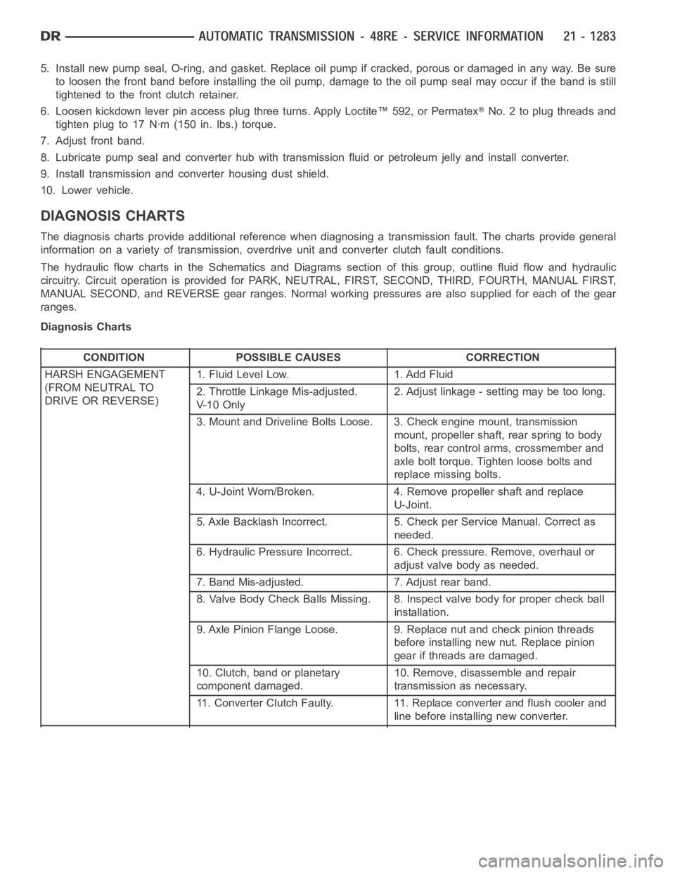
DIAGNOSIS CHARTS
The diagnosis charts provide additional reference when diagnosing a transmission fault. The charts provide general
information on a variety of transmission, overdrive unit and converter clutch fault conditions.
The hydraulic flow charts in the Schematics and Diagrams section of this group, outline fluid flow and hydraulic
circuitry. Circuit operation is provided for PARK, NEUTRAL, FIRST, SECOND, THIRD, FOURTH, MANUAL FIRST,
MANUAL SECOND, and REVERSE gear ranges. Normal working pressures are alsosupplied for each of the gear
ranges.
Diagnosis Charts
CONDITION POSSIBLE CAUSES CORRECTION
HARSH ENGAGEMENT
(FROM NEUTRAL TO
DRIVE OR REVERSE)1. Fluid Level Low. 1. Add Fluid
2. Throttle Linkage Mis-adjusted.
V- 1 0 O n l y2. Adjust linkage - setting may be too long.
3. Mount and Driveline Bolts Loose. 3. Check engine mount, transmission
mount, propeller shaft, rear spring to body
bolts, rear control arms, crossmember and
axle bolt torque. Tighten loose bolts and
replace missing bolts.
4. U-Joint Worn/Broken. 4. Remove propeller shaft and replace
U-Joint.
5. Axle Backlash Incorrect. 5. Check per Service Manual. Correct as
needed.
6. Hydraulic Pressure Incorrect. 6. Check pressure. Remove, overhaul or
adjust valve body as needed.
7. Band Mis-adjusted. 7. Adjust rear band.
8. Valve Body Check Balls Missing. 8. Inspect valve body for proper check ball
installation.
9. Axle Pinion Flange Loose. 9. Replace nut and check pinion threads
before installing new nut. Replace pinion
gear if threads are damaged.
10. Clutch, band or planetary
component damaged.10. Remove, disassemble and repair
transmission as necessary.
11. Converter Clutch Faulty. 11. Replace converter and flush cooler and
line before installing new converter.
Page 3813 of 5267
CONDITION POSSIBLE CAUSES CORRECTION
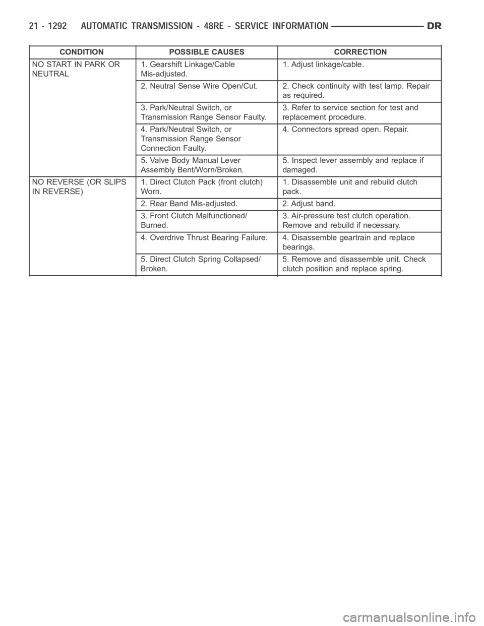
NO START IN PARK OR
NEUTRAL1. Gearshift Linkage/Cable
Mis-adjusted.1. Adjust linkage/cable.
2. Neutral Sense Wire Open/Cut. 2. Check continuity with test lamp. Repair
as required.
3. Park/Neutral Switch, or
Transmission Range Sensor Faulty.3. Refer to service section for test and
replacement procedure.
4. Park/Neutral Switch, or
Transmission Range Sensor
Connection Faulty.4. Connectors spread open. Repair.
5. Valve Body Manual Lever
Assembly Bent/Worn/Broken.5. Inspect lever assembly and replace if
damaged.
NO REVERSE (OR SLIPS
IN REVERSE)1. Direct Clutch Pack (front clutch)
Worn.1. Disassemble unit and rebuild clutch
pack.
2. Rear Band Mis-adjusted. 2. Adjust band.
3. Front Clutch Malfunctioned/
Burned.3. Air-pressure test clutch operation.
Remove and rebuild if necessary.
4. Overdrive Thrust Bearing Failure. 4. Disassemble geartrain and replace
bearings.
5. Direct Clutch Spring Collapsed/
Broken.5. Remove and disassemble unit. Check
clutch position and replace spring.
Page 3814 of 5267
CONDITION POSSIBLE CAUSES CORRECTION
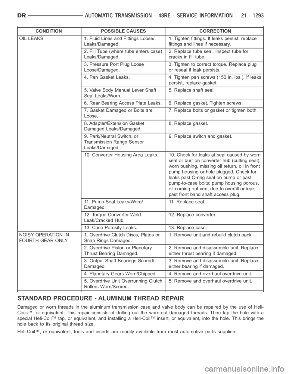
OIL LEAKS. 1. Fluid Lines and Fittings Loose/
Leaks/Damaged.1. Tighten fittings. If leaks persist, replace
fittings and lines if necessary.
2. Fill Tube (where tube enters case)
Leaks/Damaged.2. Replace tube seal. Inspect tube for
cracks in fill tube.
3. Pressure Port Plug Loose
Loose/Damaged.3. Tighten to correct torque. Replace plug
or reseal if leak persists.
4. Pan Gasket Leaks. 4. Tighten pan screws (150 in. lbs.). If leaks
persist, replace gasket.
5. Valve Body Manual Lever Shaft
Seal Leaks/Worn.5. Replace shaft seal.
6. Rear Bearing Access Plate Leaks. 6. Replace gasket. Tighten screws.
7. Gasket Damaged or Bolts are
Loose.7. Replace bolts or gasket or tighten both.
8. Adapter/Extension Gasket
Damaged Leaks/Damaged.8. Replace gasket.
9. Park/Neutral Switch, or
Transmission Range Sensor
Leaks/Damaged.9. Replace switch and gasket.
10. Converter Housing Area Leaks. 10. Check for leaks at seal caused by worn
seal or burr on converter hub (cutting seal),
worn bushing, missing oil return, oil in front
pump housing or hole plugged. Check for
leaks past O-ring seal on pump or past
pump-to-case bolts; pump housing porous,
oil coming out vent due to overfill or leak
past front band shaft access plug.
11. Pump Seal Leaks/Worn/
Damaged.11. Replace seal.
12. Torque Converter Weld
Leak/Cracked Hub.12. Replace converter.
13. Case Porosity Leaks. 13. Replace case.
NOISY OPERATION IN
FOURTH GEAR ONLY1. Overdrive Clutch Discs, Plates or
Snap Rings Damaged.1. Remove unit and rebuild clutch pack.
2. Overdrive Piston or Planetary
Thrust Bearing Damaged.2. Remove and disassemble unit. Replace
either thrust bearing if damaged.
3. Output Shaft Bearings Scored/
Damaged.3. Remove and disassemble unit. Replace
either bearing if damaged.
4. Planetary Gears Worn/Chipped. 4. Remove and overhaul overdrive unit.
5. Overdrive Unit Overrunning Clutch
Rollers Worn/Scored.5. Remove and overhaul overdrive unit.
STANDARD PROCEDURE - ALUMINUM THREAD REPAIR
DamagedorwornthreadsinthealuminumtransmissioncaseandvalvebodycanberepairedbytheuseofHeli-
Coils™, or equivalent. This repair consists of drilling out the worn-out damaged threads. Then tap the hole with a
special Heli-Coil™ tap, or equivalent, and installing a Heli-Coil™ insert, or equivalent, into the hole. This brings the
hole back to its original thread size.
Heli-Coil™, or equivalent, tools and inserts are readily available from most automotive parts suppliers.
Page 3815 of 5267
REMOVAL
NOTE: The overdrive unit can be removed and serviced separately. It is not necessary to remove the entire
transmission assembly to perform overdrive unit repairs.
1. Disconnect battery negative cable.
2. Raise vehicle.
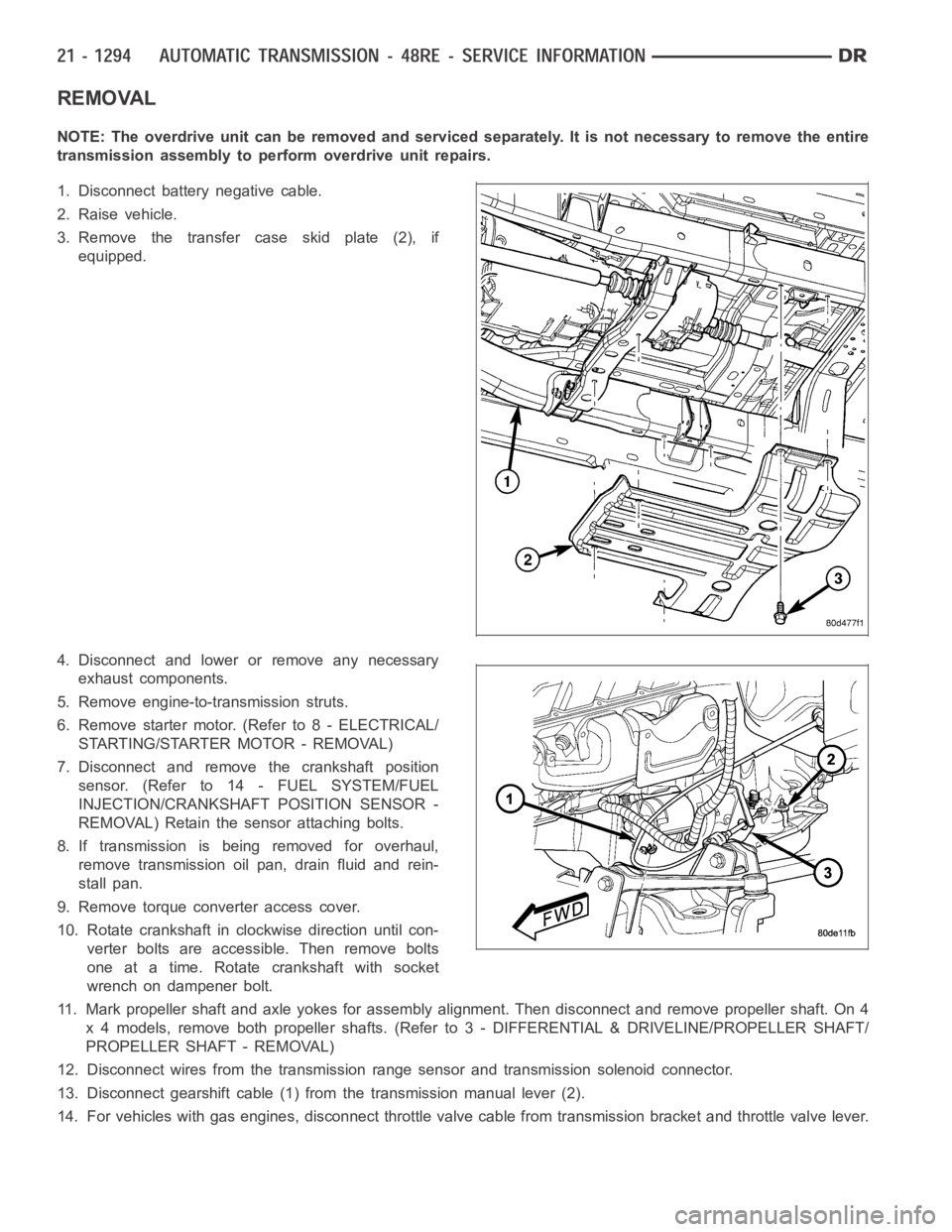
3. Remove the transfer case skid plate (2), if
equipped.
4. Disconnect and lower or remove any necessary
exhaust components.
5. Remove engine-to-transmission struts.
6. Remove starter motor. (Refer to 8 - ELECTRICAL/
STARTING/STARTER MOTOR - REMOVAL)
7. Disconnect and remove the crankshaft position
sensor. (Refer to 14 - FUEL SYSTEM/FUEL
INJECTION/CRANKSHAFT POSITION SENSOR -
REMOVAL) Retain the sensor attaching bolts.
8. If transmission is being removed for overhaul,
remove transmission oil pan, drain fluid and rein-
stall pan.
9. Remove torque converter access cover.
10. Rotate crankshaft in clockwise direction until con-
verter bolts are accessible. Then remove bolts
one at a time. Rotate crankshaft with socket
wrench on dampener bolt.
11. Mark propeller shaft and axle yokes for assembly alignment. Then disconnect and remove propeller shaft. On 4
x 4 models, remove both propeller shafts. (Refer to 3 - DIFFERENTIAL & DRIVELINE/PROPELLER SHAFT/
PROPELLER SHAFT - REMOVAL)
12. Disconnect wires from the transmission range sensor and transmissionsolenoid connector.
13. Disconnect gearshift cable (1) from the transmission manual lever (2).
14. For vehicles with gas engines, disconnect throttle valve cable from transmission bracket andthrottle valve lever.
Page 3820 of 5267
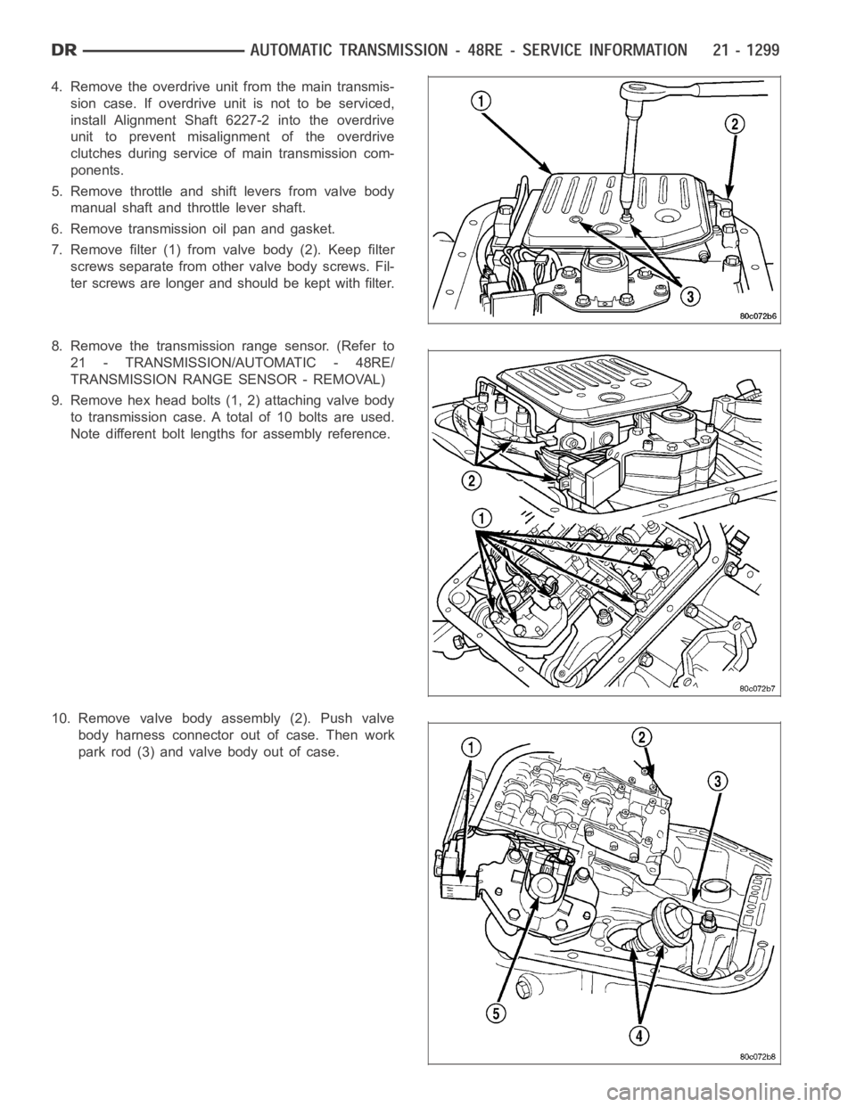
4. Removetheoverdriveunitfromthemaintransmis-
sion case. If overdrive unit is not to be serviced,
install Alignment Shaft 6227-2 into the overdrive
unit to prevent misalignment of the overdrive
clutches during service ofmain transmission com-
ponents.
5. Remove throttle and shift levers from valve body
manual shaft and throttle lever shaft.
6. Remove transmission oil pan and gasket.
7. Remove filter (1) from valve body (2). Keep filter
screws separate from other valve body screws. Fil-
ter screws are longer and should be kept with filter.
8. Remove the transmission range sensor. (Refer to
21 - TRANSMISSION/AUTOMATIC - 48RE/
TRANSMISSION RANGE SENSOR - REMOVAL)
9. Remove hex head bolts (1, 2) attaching valve body
to transmission case. A total of 10 bolts are used.
Note different bolt lengths for assembly reference.
10. Remove valve body assembly (2). Push valve
body harness connector out of case. Then work
park rod (3) and valve body out of case.
Page 3836 of 5267
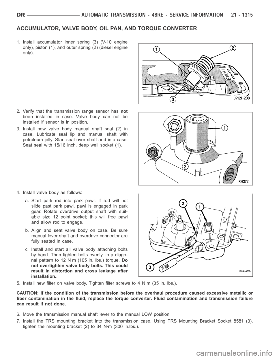
ACCUMULATOR, VALVE BODY, OIL PAN, AND TORQUE CONVERTER
1. Install accumulator inner spring (3) (V-10 engine
only), piston (1), and outer spring (2) (diesel engine
only).
2. Verify that the transmission range sensor hasnot
been installed in case. Valve body can not be
installed if sensor is in position.
3. Install new valve body manual shaft seal (2) in
case. Lubricate seal lip and manual shaft with
petroleum jelly. Start seal over shaft and into case.
Seat seal with 15/16 inch, deep well socket (1).
4. Install valve body as follows:
a. Start park rod into park pawl. If rod will not
slide past park pawl, pawl is engaged in park
gear. Rotate overdrive output shaft with suit-
able size 12 point socket; this will free pawl
and allow rod to engage.
b.Alignandseatvalvebodyoncase.Besure
manual lever shaft and overdrive connector are
fully seated in case.
c. Install and start all valve body attaching bolts
by hand. Then tighten bolts evenly, in a diago-
nal pattern to 12 Nꞏm (105 in. lbs.) torque.Do
not overtighten valve body bolts. This could
result in distortion and cross leakage after
installation..
5. Install new filter on valve body. Tighten filter screws to 4 Nꞏm (35 in. lbs.).
CAUTION: If the condition of the transmission before the overhaul procedure caused excessive metallic or
fiber contamination in the fluid, replace the torque converter. Fluid contamination and transmission failure
can result if not done.
6. Move the transmission manual shaft lever to the manual LOW position.
7. Install the TRS mounting bracket into the transmission case. Using TRS Mounting Bracket Socket 8581 (3),
tighten the mounting bracket (2) to 34 Nꞏm (300 in.lbs.).
Page 3837 of 5267
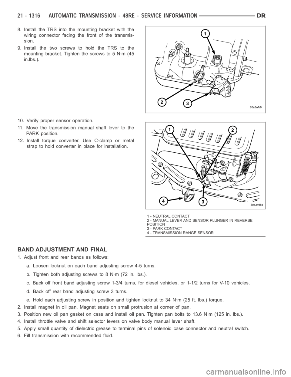
8. Install the TRS into the mounting bracket with the
wiring connector facing the front of the transmis-
sion.
9. Install the two screws to hold the TRS to the
mounting bracket. Tighten the screws to 5 Nꞏm (45
in.lbs.).
10. Verify proper sensor operation.
11. Move the transmission manual shaft lever to the
PARK position.
12. Install torque converter. Use C-clamp or metal
strap to hold converter in place for installation.
BAND ADJUSTMENT AND FINAL
1. Adjust front and rear bands as follows:
a. Loosen locknut on each band adjusting screw 4-5 turns.
b. Tighten both adjusting screws to 8 Nꞏm (72 in. lbs.).
c. Back off front band adjusting screw 1-3/4 turns, for diesel vehicles, or1-1/2 turns for V-10 vehicles.
d. Back off rear band adjusting screw 3 turns.
e. Hold each adjusting screw in position and tighten locknut to 34 Nꞏm (25 ft. lbs.) torque.
2. Install magnet in oil pan. Magnet seats on small protrusion at corner of pan.
3. Position new oil pan gasket on case and install oil pan. Tighten pan boltsto 13.6 Nꞏm (125 in. lbs.).
4. Install throttle valve and shift selector levers on valve body manual lever shaft.
5. Apply small quantity of dielectric grease to terminal pins of solenoid case connector and neutral switch.
6. Fill transmission with recommended fluid.
1 - NEUTRAL CONTACT
2 - MANUAL LEVER AND SENSOR PLUNGER IN REVERSE
POSITION
3 - PARK CONTACT
4 - TRANSMISSION RANGE SENSOR
Page 3865 of 5267
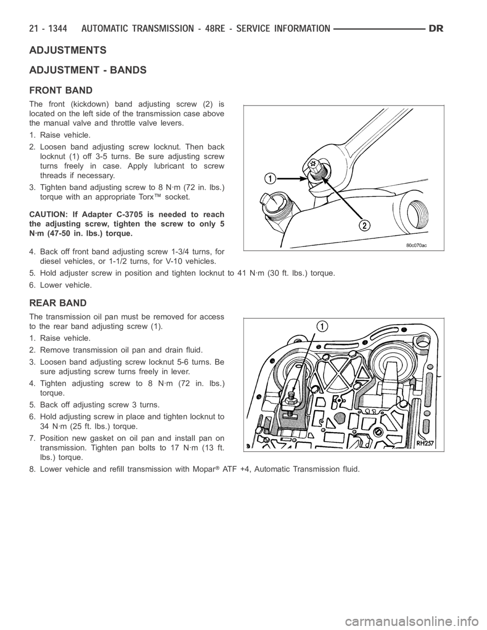
ADJUSTMENTS
ADJUSTMENT - BANDS
FRONT BAND
The front (kickdown) band adjusting screw (2) is
located on the left side of the transmission case above
the manual valve and throttle valve levers.
1. Raise vehicle.
2. Loosen band adjusting screw locknut. Then back
locknut (1) off 3-5 turns. Be sure adjusting screw
turns freely in case. Apply lubricant to screw
threads if necessary.
3. Tighten band adjusting screw to 8 Nꞏm (72 in. lbs.)
torque with an appropriate Torx™ socket.
CAUTION: If Adapter C-3705 is needed to reach
the adjusting screw, tighten the screw to only 5
Nꞏm (47-50 in. lbs.) torque.
4. Back off front band adjusting screw 1-3/4 turns, for
diesel vehicles, or 1-1/2 turns, for V-10 vehicles.
5. Hold adjuster screw in position and tighten locknut to 41 Nꞏm (30 ft. lbs.) torque.
6. Lower vehicle.
REAR BAND
The transmission oil pan must be removed for access
to the rear band adjusting screw (1).
1. Raise vehicle.
2. Remove transmission oil pan and drain fluid.
3. Loosen band adjusting screw locknut 5-6 turns. Be
sure adjusting screw turns freely in lever.
4. Tighten adjusting screw to 8 Nꞏm (72 in. lbs.)
torque.
5. Back off adjusting screw 3 turns.
6. Hold adjusting screw in place and tighten locknut to
34 Nꞏm (25 ft. lbs.) torque.
7. Position new gasket on oil pan and install pan on
transmission. Tighten pan bolts to 17 Nꞏm (13 ft.
lbs.) torque.
8. Lower vehicle and refill transmission with Mopar
ATF +4, Automatic Transmission fluid.