2006 DODGE RAM SRT-10 manual transmission
[x] Cancel search: manual transmissionPage 3492 of 5267
GEAR L/R 2C 4C UD OD
ROP OP OP OP OP
P/NCL OP OP OP OP
1STCL* OP OP CL OP
2NDOP CL OP CL OP
2ND PRIMEOP OP CL CL OP
DOP OP OP CL CL
FOURTHOP OP CL OP CL
*L/R is closed if output speed is below 100 rpm in Drive and Manual 2. L/R is open in Manual 1.
545RFE PRESSURE SWITCH STATES
GEAR L/R 2C 4C UD OD
ROP OP OP OP OP
P/NCL OP OP OP OP
1STCL* OP OP CL OP
2NDOP CL OP CL OP
2ND PRIMEOP OP CL CL OP
DOP OP OP CL CL
4THOP OP CL OP CL
5THOP CL OP OP CL
*L/R is closed if output speed is below 100 rpm in Drive and Manual 2. L/R is open in Manual 1.
A Diagnostic Trouble Code (DTC) will set if the TCM senses any switch open orclosed at the wrong time in a given
gear.
REMOVAL
NOTE: If the Transmission Solenoid/TRS Assembly is being replaced, the Quick Learn Procedure must be
performed. (Refer to 8 - ELECTRICAL/ELECTRONIC CONTROL MODULES/TRANSMISSION CONTROL MOD-
ULE - STANDARD PROCEDURE)
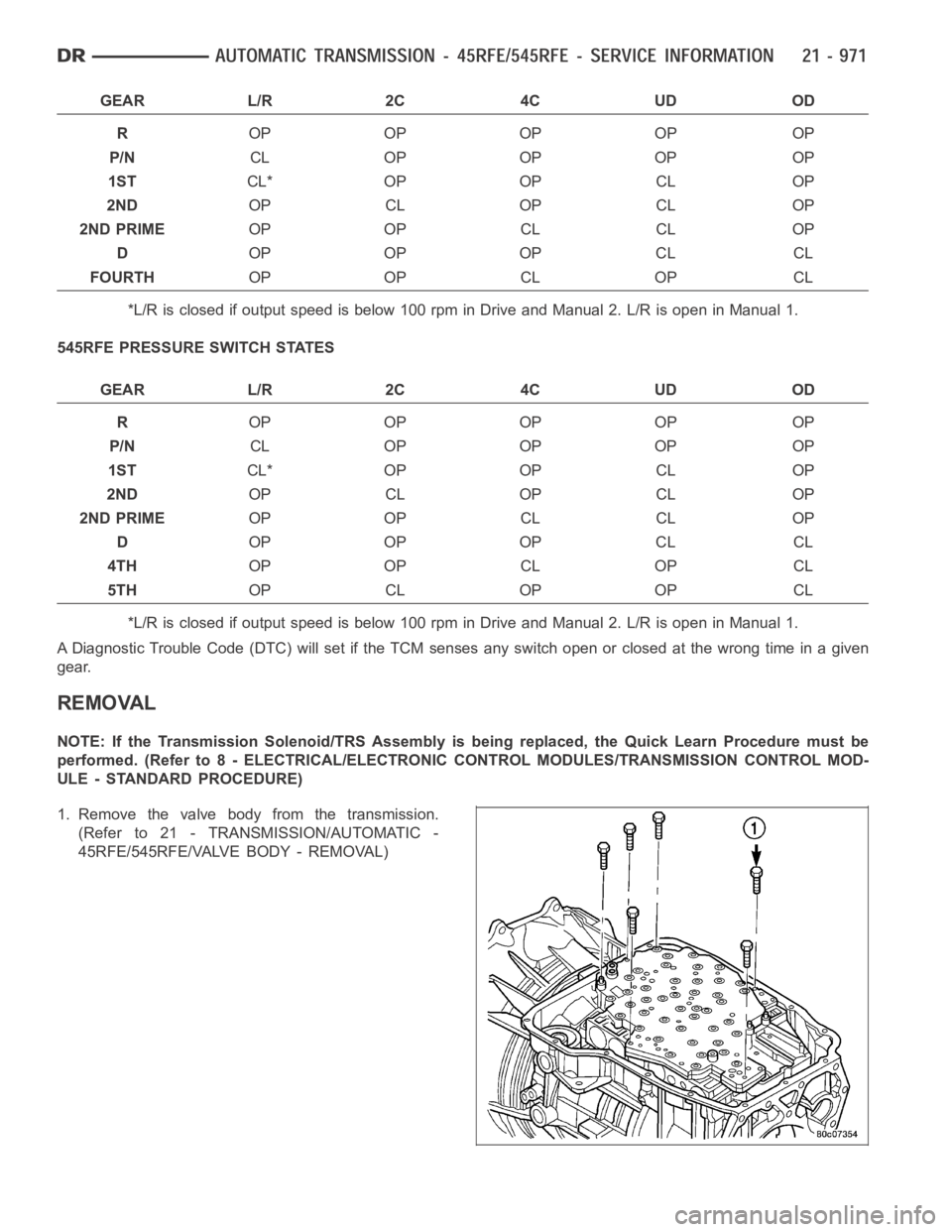
1. Remove the valve body from the transmission.
(Refer to 21 - TRANSMISSION/AUTOMATIC -
45RFE/545RFE/VALVE BODY - REMOVAL)
Page 3496 of 5267
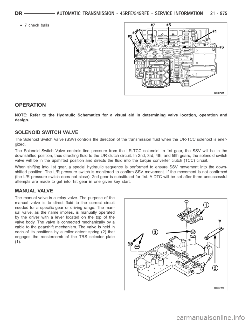
7 check balls
OPERATION
NOTE: Refer to the Hydraulic Schematics for a visual aid in determining valve location, operation and
design.
SOLENOID SWITCH VALVE
The Solenoid Switch Valve (SSV) controls the direction of the transmission fluid when the L/R-TCC solenoid is ener-
gized.
The Solenoid Switch Valve controls line pressure from the LR-TCC solenoid. In 1st gear, the SSV will be in the
downshifted position, thus directing fluid to the L/R clutch circuit. In 2nd, 3rd, 4th, and fifth gears, the solenoid switch
valve will be in the upshifted position and directs the fluid into the torque converter clutch (TCC) circuit.
When shifting into 1st gear, a special hydraulic sequence is performed to ensure SSV movement into the down-
shifted position. The L/R pressure switch is monitored to confirm SSV movement. If the movement is not confirmed
(the L/R pressure switch does not close), 2nd gear is substituted for 1st. ADTC will be set after three unsuccessful
attempts are made to get into 1st gear in one given key start.
MANUAL VALVE
The manual valve is a relay valve. The purpose of the
manual valve is to direct fluid to the correct circuit
needed for a specific gear or driving range. The man-
ual valve, as the name implies, is manually operated
by the driver with a lever located on the top of the
valve body. The valve is connected mechanically by a
cable to the gearshift mechanism. The valve is held in
each of its positions by a roller detent spring (2) that
engages the roostercomb of the TRS selector plate
(1).
Page 3504 of 5267
ASSEMBLY
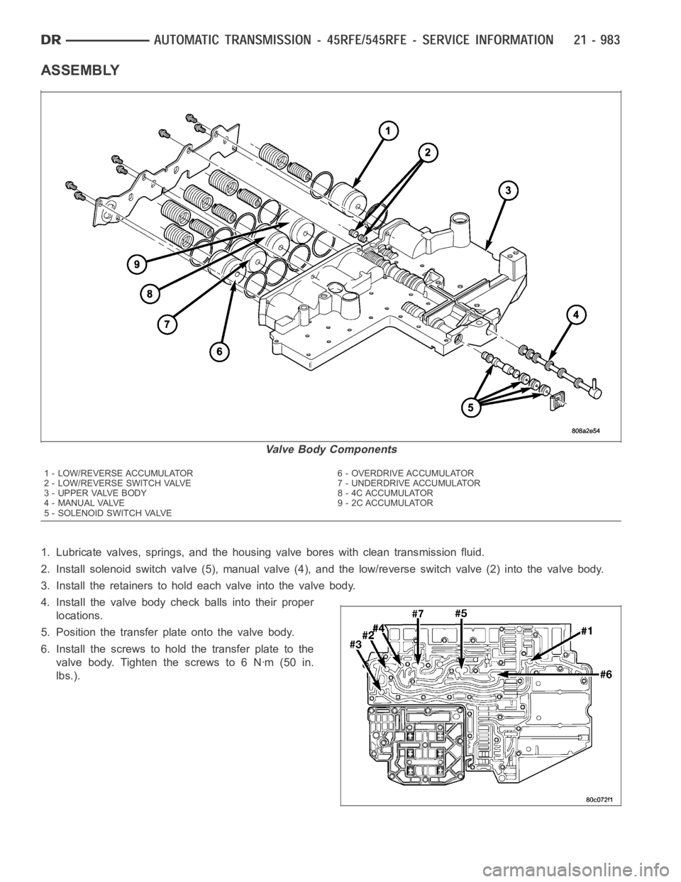
1. Lubricate valves, springs, and the housing valve bores with clean transmission fluid.
2. Install solenoid switch valve (5), manual valve (4), and the low/reverseswitchvalve(2)intothevalvebody.
3. Install the retainers to hold each valve into the valve body.
4. Install the valve body check balls into their proper
locations.
5. Position the transfer plate onto the valve body.
6. Install the screws to hold the transfer plate to the
valve body. Tighten the screws to 6 Nꞏm (50 in.
lbs.).
Valve Body Components
1 - LOW/REVERSE ACCUMULATOR 6 - OVERDRIVE ACCUMULATOR
2 - LOW/REVERSE SWITCH VALVE 7 - UNDERDRIVE ACCUMULATOR
3 - UPPER VALVE BODY 8 - 4C ACCUMULATOR
4 - MANUAL VALVE 9 - 2C ACCUMULATOR
5 - SOLENOID SWITCH VALVE
Page 3507 of 5267
INSTALLATION
1. Check condition of seals on valve body and the
solenoid and pressure switch assembly. Replace
seals if cut or worn.
2. Place TRS selector plate in the PARK position.
3. Place the transmission in the PARK position.
4. Lubricate seal on the solenoid and pressure switch
assembly connector with petroleum jelly.
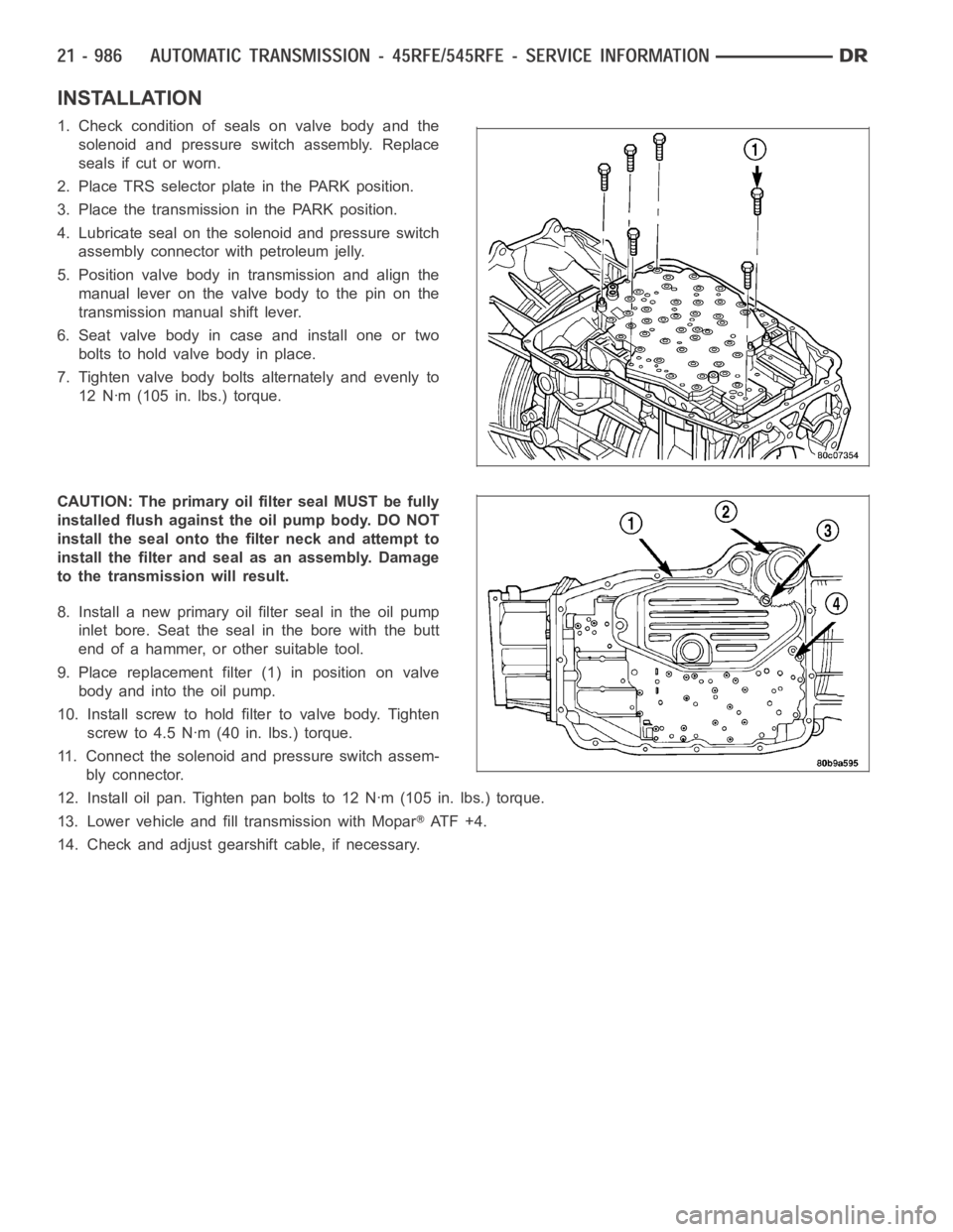
5. Position valve body in transmission and align the
manual lever on the valve body to the pin on the
transmission manual shift lever.
6. Seat valve body in case and install one or two
bolts to hold valve body in place.
7. Tighten valve body bolts alternately and evenly to
12 Nꞏm (105 in. lbs.) torque.
CAUTION: The primary oil filter seal MUST be fully
installed flush against the oil pump body. DO NOT
install the seal onto the filter neck and attempt to
install the filter and seal as an assembly. Damage
to the transmission will result.
8. Install a new primary oil filter seal in the oil pump
inlet bore. Seat the seal in the bore with the butt
end of a hammer, or other suitable tool.
9. Place replacement filter (1) in position on valve
body and into the oil pump.
10. Install screw to hold filter to valve body. Tighten
screw to 4.5 Nꞏm (40 in. lbs.) torque.
11. Connect the solenoid and pressure switch assem-
bly connector.
12. Install oil pan. Tighten pan bolts to 12 Nꞏm (105 in. lbs.) torque.
13. Lower vehicle and fill transmission with Mopar
AT F + 4 .
14. Check and adjust gearshift cable, if necessary.
Page 3792 of 5267
OPERATION
The application of each driving or holding component is controlled by the valve body based upon the manual lever
position, throttle pressure, and governor pressure. The governor pressure is a variable pressure input to the valve
body and is one of the signals that a shift is necessary. First through fourth gear are obtained by selectively apply-
ing and releasing the different clutches and bands. Engine power is thereby routed to the various planetary gear
assemblies which combine with the overrunning clutch assemblies to generate the different gear ratios. The torque
converter clutch is hydraulically applied and is released when fluid is vented from the hydraulic circuit by the torque
converter control (TCC) solenoid on the valve body. The torque converter clutch is controlled by the Powertrain
Control Module (PCM). The torque converter clutch engages in fourth gear,and in third gear under various condi-
tions, such as when the O/D switch is OFF, when the vehicle is cruising on a level surface after the vehicle has
warmed up. The torque converter clutch can also be engaged in the MANUAL SECOND gear position if high trans-
mission temperatures are sensed by the PCM. The torque converter clutch will disengage momentarily when an
increase in engine load is sensed by the PCM, such as when the vehicle beginsto go uphill or the throttle pressure
is increased. The torque converter clutch feature increases fuel economyand reduces the transmission fluid tem-
perature.
Since the overdrive clutch is applied in fourth gear only and the direct clutch is applied in all ranges except fourth
gear, the transmission operation for park, neutral, and first through third gear will be described first. Once these
powerflows are described, the third to fourth shift sequence will be described.
PARK POWERFLOW
As the engine is running and the crankshaft is rotat-
ing, the flexplate and torque converter, which are also
bolted to it, are all rotating in a clockwise direction as
viewed from the front of the engine. The notched hub
of the torque converter is connected to the oil pump’s
internal gear, supplying the transmission with oil pres-
sure. As the converter turns, it turns the input shaft in
a clockwise direction. As the input shaft is rotating, the
front clutch hub-rear clutch retainer and all their asso-
ciated parts are also rotating, all being directly con-
nected to the input shaft. The power flow from the
engine through the front clutch hub and rear clutch
retainer stops at the rear clutch retainer. Therefore, no
power flow to the output shaft occurs because no
clutches are applied. The only mechanism in use at
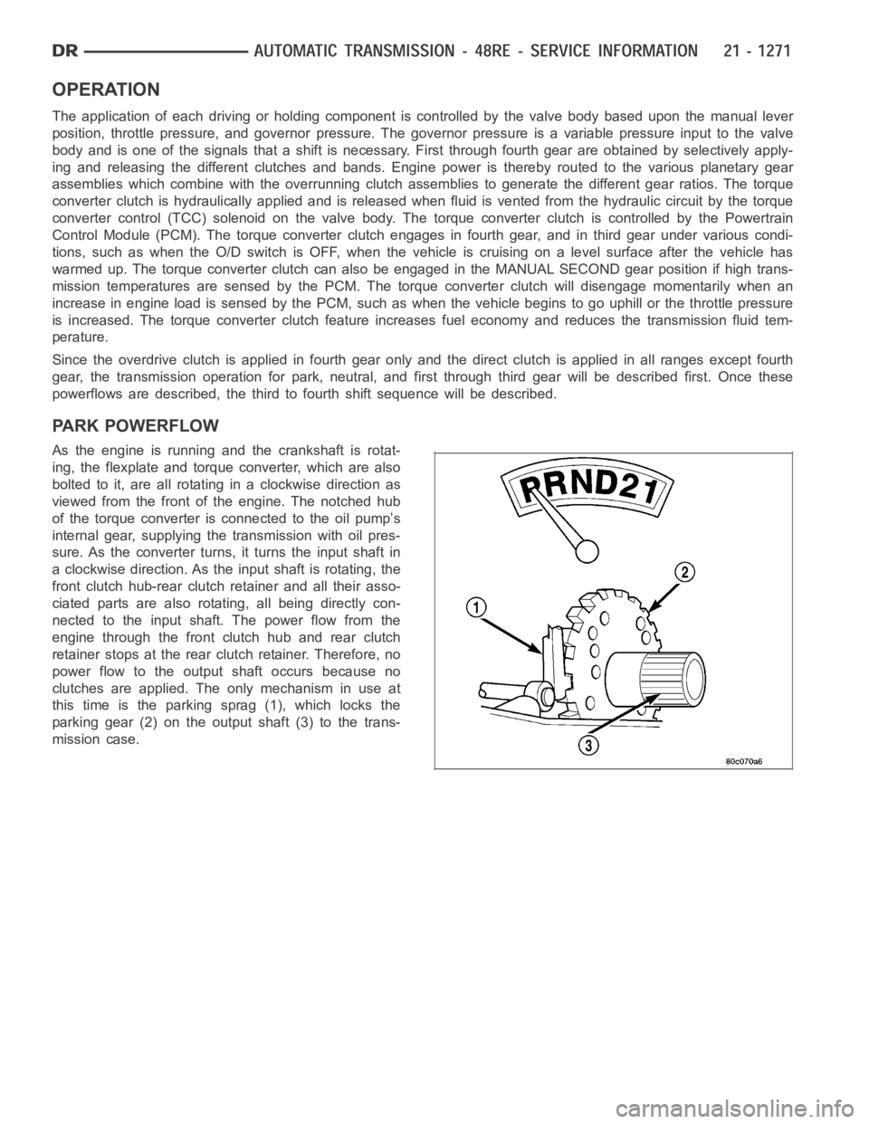
this time is the parking sprag (1), which locks the
parking gear (2) on the output shaft (3) to the trans-
mission case.
Page 3796 of 5267
SECOND GEAR POWERFLOW
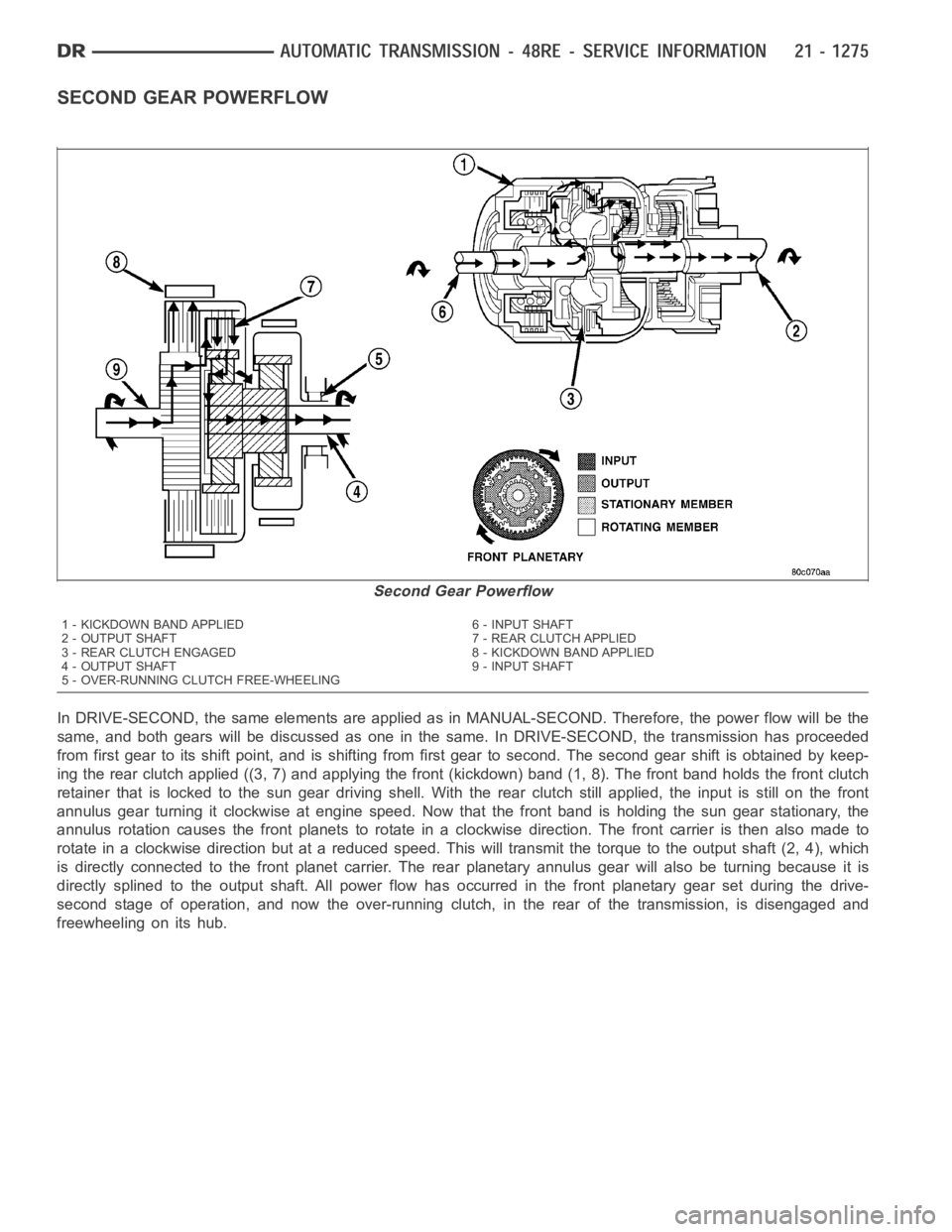
In DRIVE-SECOND, the same elements are applied as in MANUAL-SECOND. Therefore, the power flow will be the
same, and both gears will be discussed as one in the same. In DRIVE-SECOND, the transmission has proceeded
from first gear to its shift point, and is shifting from first gear to second. The second gear shift is obtained by keep-
ing the rear clutch applied ((3, 7) and applying the front (kickdown) band (1, 8). The front band holds the front clutch
retainer that is locked to the sun gear driving shell. With the rear clutch still applied, the input is still on the front
annulus gear turning it clockwise at engine speed. Now that the front band is holding the sun gear stationary, the
annulus rotation causes the front planets to rotate in a clockwise direction. The front carrier is then also made to
rotate in a clockwise direction but at a reduced speed. This will transmit the torque to the output shaft (2, 4), which
is directly connected to the front planet carrier. The rear planetary annulus gear will also be turning because it is
directly splined to the output shaft. All power flow has occurred in the front planetary gear set during the drive-
second stage of operation, and now the over-running clutch, in the rear of the transmission, is disengaged and
freewheeling on its hub.
Second Gear Powerflow
1 - KICKDOWN BAND APPLIED 6 - INPUT SHAFT
2 - OUTPUT SHAFT 7 - REAR CLUTCH APPLIED
3 - REAR CLUTCH ENGAGED 8 - KICKDOWN BAND APPLIED
4 - OUTPUT SHAFT 9 - INPUT SHAFT
5 - OVER-RUNNING CLUTCH FREE-WHEELING
Page 3799 of 5267
SHIFT
LEVER
POSITIONTRANSMISSION CLUTCHES AND BANDS OVERDRIVE CLUTCHES
FRONT
CLUTCHFRONT
BANDREAR
CLUTCHREAR
BANDOVER-
RUNNING
CLUTCHOVER-
DRIVE
CLUTCHDIRECT
CLUTCHOVER-
RUNNING
CLUTCH
ReverseXXX
Drive -
FirstXXXX
Drive -
SecondXX X X
Drive -
ThirdXX XX
Drive -
FourthXX X
Manual
SecondXX X X
Manual
FirstXXX X X
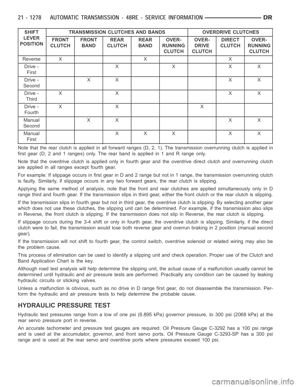
Note that the rear clutch is applied in all forward ranges (D, 2, 1). The transmission overrunning clutch is applied in
first gear (D, 2 and 1 ranges) only. The rear band is applied in 1 and R range only.
Note that the overdrive clutch is applied only in fourth gear and the overdrive direct clutch and overrunning clutch
are applied in all ranges except fourth gear.
For example: If slippage occurs in first gear in D and 2 range but not in 1 range, the transmission overrunning clutch
is faulty. Similarly, if slippage occurs in any two forward gears, the rearclutch is slipping.
Applying the same method of analysis, note that the front and rear clutchesare applied simultaneously only in D
range third and fourth gear. If the transmission slips in third gear, either the front clutch or the rear clutch is slipping.
Ifthetransmissionslipsinfourthgearbutnotinthirdgear,theoverdrive clutch is slipping. By selecting another gear
which does not use these clutches, the slipping unit can be determined. Forexample, if the transmission also slips
in Reverse, the front clutch is slipping. If the transmission does not slipin Reverse, the rear clutch is slipping.
If slippage occurs during the 3-4 shift or only in fourth gear, the overdrive clutch is slipping. Similarly, if the direct
clutch were to fail, the transmission would lose both reverse gear and overrun braking in 2 position (manual second
gear).
If the transmission will not shift to fourth gear, the control switch, overdrive solenoid or related wiring may also be
the problem cause.
This process of elimination can be used to identify a slipping unit and check operation. Proper use of the Clutch and
Band Application Chart is the key.
Although road test analysis will help determine the slipping unit, the actual cause of a malfunction usually cannot be
determined until hydraulic and air pressure tests are performed. Practically any condition can be caused by leaking
hydraulic circuits or sticking valves.
Unless a malfunction is obvious, such as no drive in D range first gear, do not disassemble the transmission. Per-
form the hydraulic and air pressure tests to help determine the probable cause.
HYDRAULIC PRESSURE TEST
Hydraulic test pressures range from a low of one psi (6.895 kPa) governor pressure, to 300 psi (2068 kPa) at the
rear servo pressure port in reverse.
An accurate tachometer and pressure test gauges are required. Oil Pressure Gauge C-3292 has a 100 psi range
and is used at the accumulator, governor, and front servo ports. Oil Pressure Gauge C-3293-SP has a 300 psi
range and is used at the rear servo and overdrive ports where pressures exceed 100 psi.
Page 3800 of 5267
Pressure Test Port Locations
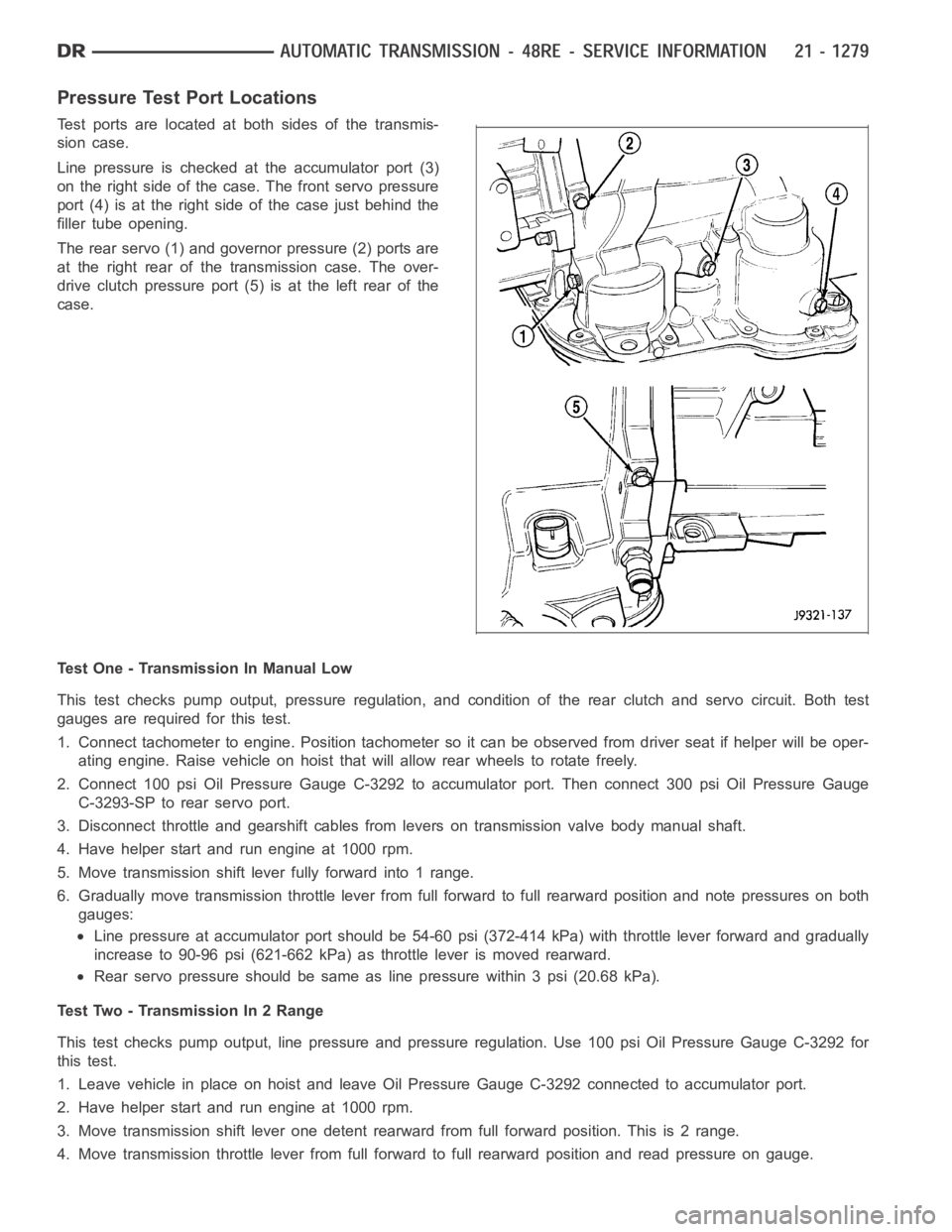
Test ports are located at both sides of the transmis-
sion case.
Line pressure is checked at the accumulator port (3)
on the right side of the case. The front servo pressure
port (4) is at the right side of the case just behind the
filler tube opening.
The rear servo (1) and governor pressure (2) ports are
at the right rear of the transmission case. The over-
drive clutch pressure port (5) is at the left rear of the
case.
Test One - Transmission In Manual Low
This test checks pump output, pressure regulation, and condition of the rear clutch and servo circuit. Both test
gauges are required for this test.
1. Connect tachometer to engine. Position tachometer so it can be observedfrom driver seat if helper will be oper-
ating engine. Raise vehicle on hoist that will allow rear wheels to rotate freely.
2. Connect 100 psi Oil Pressure Gauge C-3292 to accumulator port. Then connect 300 psi Oil Pressure Gauge
C-3293-SP to rear servo port.
3. Disconnect throttle and gearshift cables from levers on transmission valve body manual shaft.
4. Have helper start and run engine at 1000 rpm.
5. Move transmission shift lever fully forward into 1 range.
6. Gradually move transmission throttle lever from full forward to full rearward position and note pressures on both
gauges:
Line pressure at accumulator port should be 54-60 psi (372-414 kPa) with throttle lever forward and gradually
increase to 90-96 psi (621-662 kPa) as throttle lever is moved rearward.
Rear servo pressure should be same asline pressure within 3 psi (20.68 kPa).
Test Two - Transmission In 2 Range
This test checks pump output, line pressure and pressure regulation. Use 100 psi Oil Pressure Gauge C-3292 for
this test.
1. Leave vehicle in place on hoist and leave Oil Pressure Gauge C-3292 connected to accumulator port.
2. Have helper start and run engine at 1000 rpm.
3. Move transmission shift lever one detent rearward from full forward position. This is 2 range.
4. Move transmission throttle lever from full forward to full rearward position and read pressure on gauge.