2006 DODGE RAM SRT-10 manual transmission
[x] Cancel search: manual transmissionPage 3887 of 5267
CABLE-GEARSHIFT
DIAGNOSIS AND TESTING - GEARSHIFT CABLE
1. Engine starts must be possible with shift lever in PARK or NEUTRAL positions only. Engine starts must not be
possible in any other gear position.
2. With the shift lever in the:
a. PARK position - Apply upward force on the shift arm and remove pressure. Engine starts must be possible.
b. PARK position - Apply downward force on the shift arm and remove pressure. Engine starts must be pos-
sible.
c. NEUTRAL position - Normal position. Engine starts must be possible.
d. NEUTRAL position - Engine running and brakes applied, apply upward forceontheshiftarm.Transmission
shall not be able to shift from neutral to reverse.
REMOVAL
1. Shift transmission into PARK.
2. Raise vehicle.
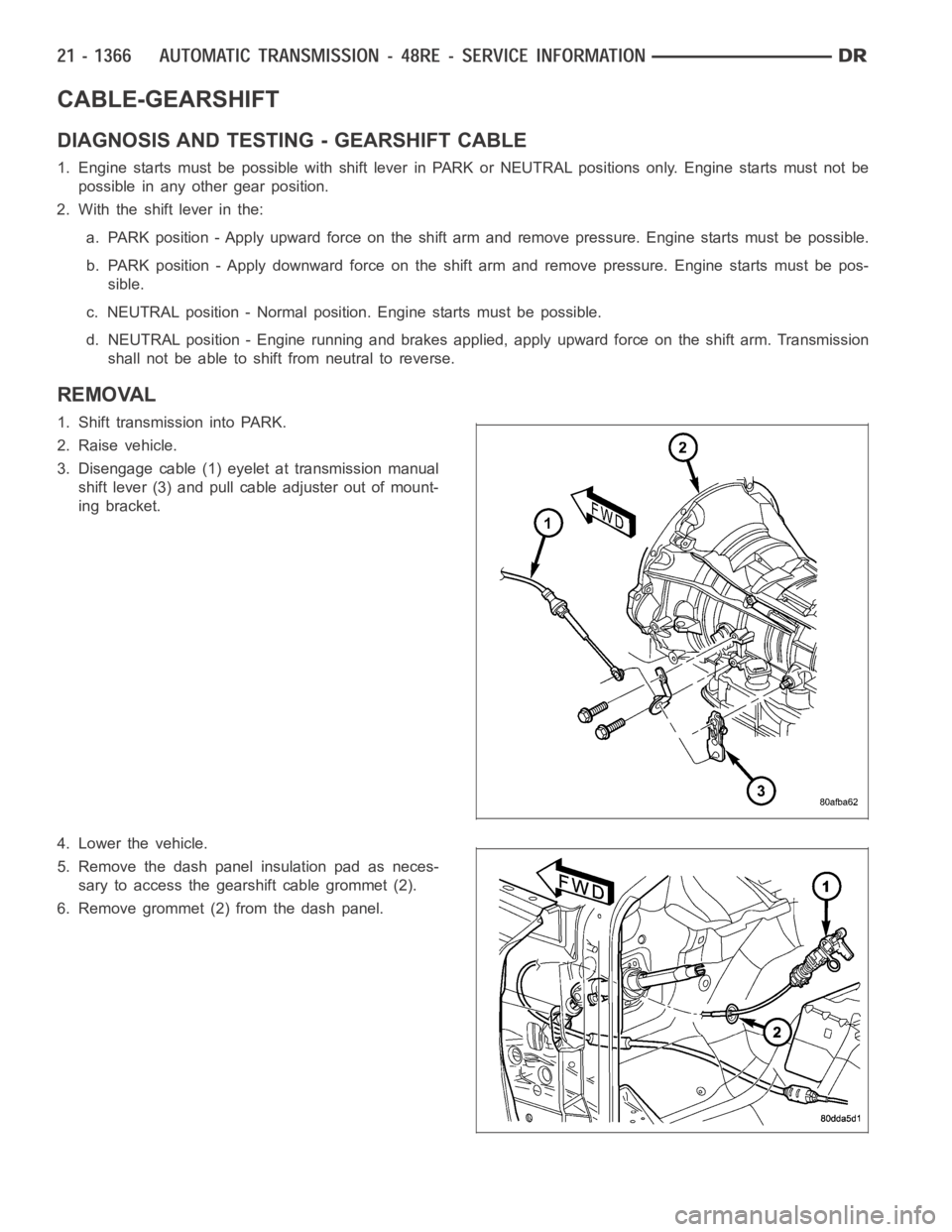
3. Disengage cable (1) eyelet at transmission manual
shift lever (3) and pull cable adjuster out of mount-
ing bracket.
4. Lower the vehicle.
5. Remove the dash panel insulation pad as neces-
sary to access the gearshift cable grommet (2).
6. Remove grommet (2) from the dash panel.
Page 3888 of 5267
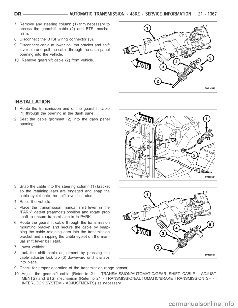
7. Remove any steering column (1) trim necessary to
access the gearshift cable (2) and BTSI mecha-
nism.
8. Disconnect the BTSI wiring connector (5).
9. Disconnect cable at lower column bracket and shift
lever pin and pull the cable through the dash panel
opening into the vehicle.
10. Remove gearshift cable (2) from vehicle.
INSTALLATION
1. Route the transmission end of the gearshift cable
(1) through the opening in the dash panel.
2. Seat the cable grommet (2) into the dash panel
opening.
3. Snap the cable into the steering column (1) bracket
so the retaining ears are engaged and snap the
cable eyelet onto the shift lever ball stud.
4. Raise the vehicle.
5. Place the transmission manual shift lever in the
“PARK” detent (rearmost) position and rotate prop
shaft to ensure transmission is in PARK.
6. Route the gearshift cable through the transmission
mounting bracket and secure the cable by snap-
ping the cable retaining ears into the transmission
bracket and snapping the cable eyelet on the man-
ual shift lever ball stud.
7. Lower vehicle.
8. Lock the shift cable adjustment by pressing the
cable adjuster lock tab (3) downward until it snaps
into place.
9. Check for proper operation of the transmission range sensor.
10. Adjust the gearshift cable (Refer to 21 - TRANSMISSION/AUTOMATIC/GEAR SHIFT CABLE - ADJUST-
MENTS) and BTSI mechanism (Refer to 21 - TRANSMISSION/AUTOMATIC/BRAKE TRANSMISSION SHIFT
INTERLOCK SYSTEM - ADJUSTMENTS) as necessary.
Page 3889 of 5267
ADJUSTMENTS - GEARSHIFT CABLE
Check adjustment by starting the engine in PARK and NEUTRAL. Adjustment isCORRECT if the engine starts only
in these positions. Adjustment is INCORRECT if the engine starts in one butnot both positions. If the engine starts
in any position other than PARK or NEUTRAL, or if the engine will not start atall, the transmission range sensor
may be faulty.
Gearshift Adjustment Procedure
1. Shift transmission into PARK.
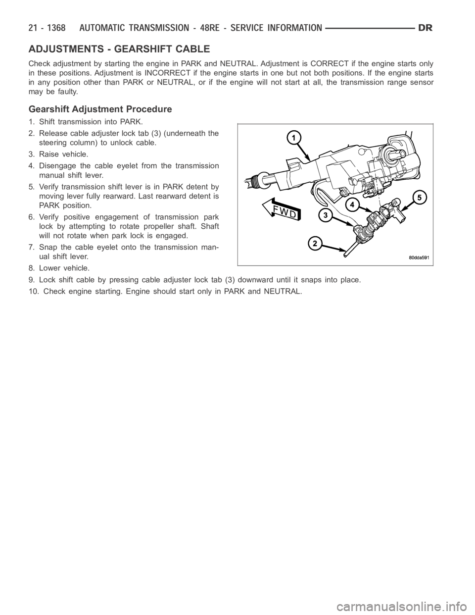
2. Release cable adjuster lock tab (3) (underneath the
steering column) to unlock cable.
3. Raise vehicle.
4. Disengage the cable eyelet from the transmission
manual shift lever.
5. Verify transmission shift lever is in PARK detent by
moving lever fully rearward. Last rearward detent is
PARK position.
6. Verify positive engagement of transmission park
lock by attempting to rotate propeller shaft. Shaft
will not rotate when park lock is engaged.
7. Snap the cable eyelet onto the transmission man-
ual shift lever.
8. Lower vehicle.
9. Lock shift cable by pressing cable adjuster lock tab (3) downward until it snaps into place.
10. Check engine starting. Engine should start only in PARK and NEUTRAL.
Page 3943 of 5267
MECHANISM-SHIFT
DESCRIPTION
The gear shift mechanism provides six shift positions which are:
PA R K ( P )
REVERSE (R)
NEUTRAL (N)
DRIVE (D)
Manual SECOND (2)
Manual LOW (1)
OPERATION
Manual LOW (1) range provides first gear only. Overrun braking is also provided in this range. Manual SECOND (2)
range provides first and second gear only.
DRIVE range provides first, second, third, and overdrive fourth gear ranges. The shift into overdrive fourth gear
range occurs only after the transmission has completed the shift into D third gear range. No further movement of the
shift mechanism is required to complete the 3-4 shift.
The fourth gear upshift occurs automatically when the overdrive selectorswitch is in the ON position. No upshift to
fourth gear will occur if any of the following are true:
The transmission fluid temperature is below 10° C (50° F) or above 121° C (250° F).
The shift to third is not yet complete.
Vehicle speed is too low for the 3-4 shift to occur.
Battery temperature is below -5° C (23° F).
Page 3957 of 5267
STATOR
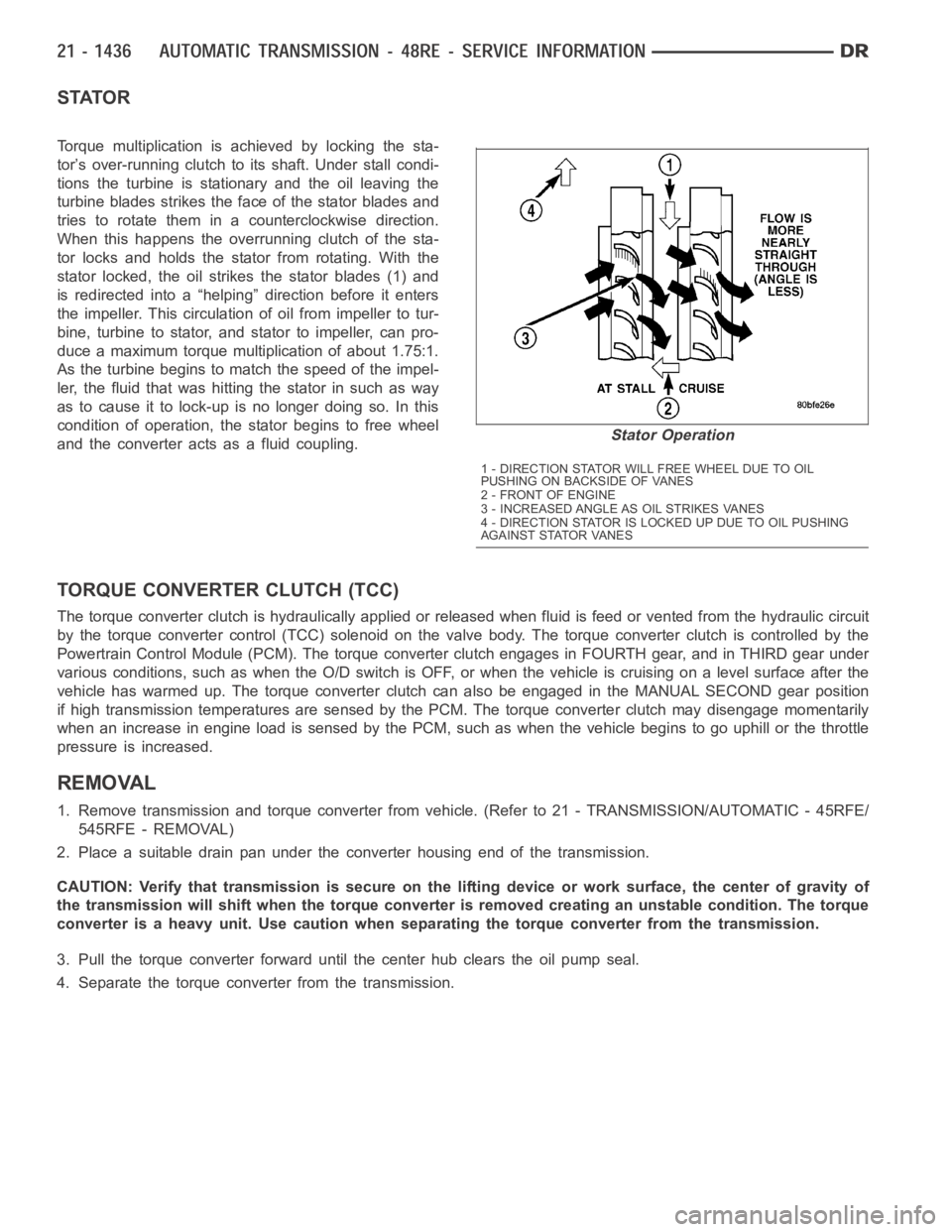
Torque multiplication is achieved by locking the sta-
tor’s over-running clutch to its shaft. Under stall condi-
tions the turbine is stationary and the oil leaving the
turbine blades strikes the face of the stator blades and
tries to rotate them in a counterclockwise direction.
When this happens the overrunning clutch of the sta-
tor locks and holds the stator from rotating. With the
stator locked, the oil strikes the stator blades (1) and
is redirected into a “helping” direction before it enters
the impeller. This circulation of oil from impeller to tur-
bine, turbine to stator, and stator to impeller, can pro-
duce a maximum torque multiplication of about 1.75:1.
As the turbine begins to match the speed of the impel-
ler, the fluid that was hitting the stator in such as way
as to cause it to lock-up is no longer doing so. In this
condition of operation, the stator begins to free wheel
and the converter acts as a fluid coupling.
TORQUE CONVERTER CLUTCH (TCC)
The torque converter clutch is hydraulically applied or released when fluid is feed or vented from the hydraulic circuit
by the torque converter control (TCC) solenoid on the valve body. The torque converter clutch is controlled by the
Powertrain Control Module (PCM). The torque converter clutch engages in FOURTH gear, and in THIRD gear under
various conditions, such as when the O/D switch is OFF, or when the vehicle is cruising on a level surface after the
vehicle has warmed up. The torque converter clutch can also be engaged in the MANUAL SECOND gear position
if high transmission temperatures are sensed by the PCM. The torque converter clutch may disengage momentarily
when an increase in engine load is sensed by the PCM, such as when the vehiclebegins to go uphill or the throttle
pressure is increased.
REMOVAL
1. Remove transmission and torque converter from vehicle. (Refer to 21 - TRANSMISSION/AUTOMATIC - 45RFE/
545RFE - REMOVAL)
2. Place a suitable drain pan under the converter housing end of the transmission.
CAUTION: Verify that transmission is secure on the lifting device or work surface, the center of gravity of
the transmission will shift when the torque converter is removed creatingan unstable condition. The torque
converter is a heavy unit. Use caution when separating the torque converter from the transmission.
3. Pull the torque converter forward until the center hub clears the oil pumpseal.
4. Separate the torque converter from the transmission.
Stator Operation
1 - DIRECTION STATOR WILL FREE WHEEL DUE TO OIL
PUSHING ON BACKSIDE OF VANES
2-FRONTOFENGINE
3 - INCREASED ANGLE AS OIL STRIKES VANES
4 - DIRECTION STATOR IS LOCKED UP DUE TO OIL PUSHING
AGAINST STATOR VANES
Page 3963 of 5267
SENSOR-TRANSMISSION RANGE
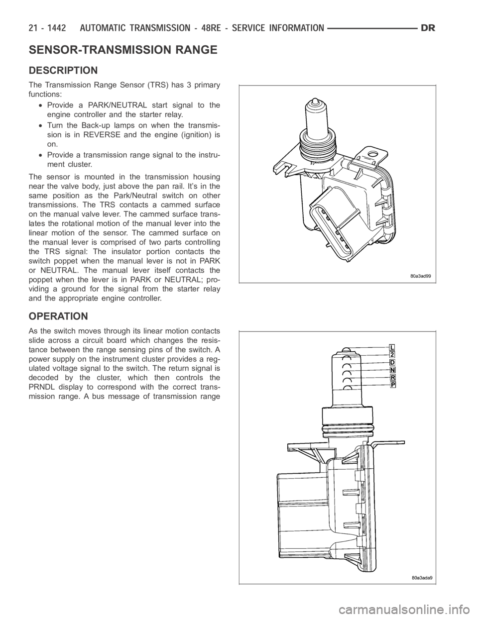
DESCRIPTION
The Transmission Range Sensor (TRS) has 3 primary
functions:
Provide a PARK/NEUTRAL start signal to the
engine controller and the starter relay.
Turn the Back-up lamps on when the transmis-
sion is in REVERSE and the engine (ignition) is
on.
Provide a transmission range signal to the instru-
ment cluster.
The sensor is mounted in the transmission housing
near the valve body, just above the pan rail. It’s in the
same position as the Park/Neutral switch on other
transmissions. The TRS contacts a cammed surface
on the manual valve lever. The cammed surface trans-
lates the rotational motion of the manual lever into the
linear motion of the sensor. The cammed surface on
the manual lever is comprised of two parts controlling
the TRS signal: The insulator portion contacts the
switch poppet when the manual lever is not in PARK
or NEUTRAL. The manual lever itself contacts the
poppet when the lever is in PARK or NEUTRAL; pro-
viding a ground for the signal from the starter relay
and the appropriate engine controller.
OPERATION
As the switch moves through its linear motion contacts
slide across a circuit board which changes the resis-
tance between the range sensing pins of the switch. A
power supply on the instrument cluster provides a reg-
ulated voltage signal to the switch. The return signal is
decoded by the cluster, which then controls the
PRNDL display to correspond with the correct trans-
mission range. A bus message of transmission range
Page 3964 of 5267
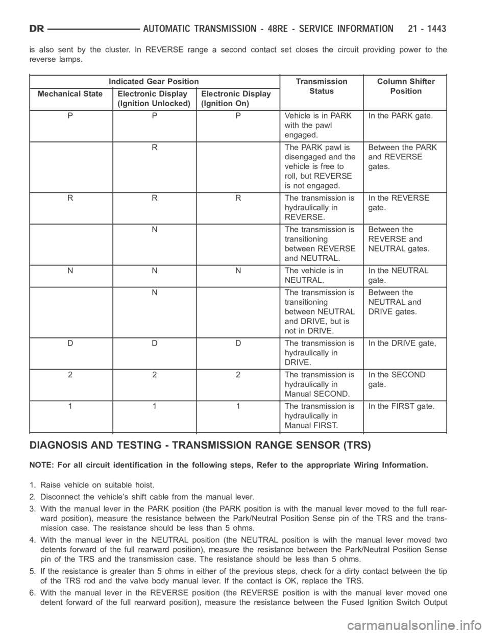
is also sent by the cluster. In REVERSE range a second contact set closes thecircuit providing power to the
reverse lamps.
Indicated Gear Position Transmission
StatusColumn Shifter
Position
Mechanical State Electronic Display
(Ignition Unlocked)Electronic Display
(Ignition On)
P P P Vehicle is in PARK
with the pawl
engaged.In the PARK gate.
R The PARK pawl is
disengaged and the
vehicle is free to
roll, but REVERSE
is not engaged.Between the PARK
and REVERSE
gates.
R R R The transmission is
hydraulically in
REVERSE.In the REVERSE
gate.
N The transmission is
transitioning
between REVERSE
and NEUTRAL.Between the
REVERSE and
NEUTRAL gates.
N N N The vehicle is in
NEUTRAL.In the NEUTRAL
gate.
N The transmission is
transitioning
between NEUTRAL
and DRIVE, but is
not in DRIVE.Between the
NEUTRAL and
DRIVE gates.
D D D The transmission is
hydraulically in
DRIVE.In the DRIVE gate,
2 2 2 The transmission is
hydraulically in
Manual SECOND.In the SECOND
gate.
1 1 1 The transmission is
hydraulically in
Manual FIRST.In the FIRST gate.
DIAGNOSIS AND TESTING - TRANSMISSION RANGE SENSOR (TRS)
NOTE: For all circuit identification in the following steps, Refer to the appropriate Wiring Information.
1. Raise vehicle on suitable hoist.
2. Disconnect the vehicle’s shift cable from the manual lever.
3. With the manual lever in the PARK position (the PARK position is with the manual lever moved to the full rear-
ward position), measure the resistance between the Park/Neutral PositionSensepinoftheTRSandthetrans-
mission case. The resistance should be less than 5 ohms.
4. With the manual lever in the NEUTRAL position (the NEUTRAL position is with the manual lever moved two
detents forward of the full rearward position), measure the resistance between the Park/Neutral Position Sense
pin of the TRS and the transmission case. The resistance should be less than5ohms.
5. If the resistance is greater than 5 ohms in either of the previous steps, check for a dirty contact between the tip
of the TRS rod and the valve body manual lever. If the contact is OK, replace the TRS.
6. With the manual lever in the REVERSE position (the REVERSE position is with the manual lever moved one
detent forward of the full rearward position), measure the resistance between the Fused Ignition Switch Output
Page 3965 of 5267

and the Back-up Lamp feed pins of the TRS. The resistance should be less than5 ohms. If the resistance is
greater than 5 ohms, replace the TRS.
7. With the manual lever in the PARK position (the PARK position is with the manual lever moved to the full rear-
ward position), measure the resistance between the Transmission Range Sensor MUX and the Transmission
Range Sensor 5V Supply pins of the TRS. The resistance should be 522.2 ohms.If the resistance is not correct,
replace the TRS.
8. With the manual lever in the REVERSE position (the REVERSE position is with the manual lever moved one
detent forward of the full rearward position), measure the resistance between the Transmission Range Sensor
MUX and the Transmission Range Sensor 5V Supply pins of the TRS. The resistance should be 206.2 ohms. If
the resistance is not correct, replace the TRS.
9. With the manual lever in the NEUTRAL position (the NEUTRAL position is with the manual lever moved two
detents forward of the full rearward position), measure the resistance between the Transmission Range Sensor
MUX and the Transmission Range Sensor 5V Supply pins of the TRS. The resistance should be 108.6 ohms. If
the resistance is not correct, replace the TRS.
10. With the manual lever in the DRIVE position (the DRIVE position is with the manual lever moved three detents
forward of the full rearward position), measure the resistance between the Transmission Range Sensor MUX
and the Transmission Range Sensor 5V Supply pins of the TRS. The resistanceshould be 59.9 ohms. If the
resistance is not correct, replace the TRS.
11. With the manual lever in the SECOND position (the SECOND position is with the manual lever moved one
detent rearward of the full forward position), measure the resistance between the Transmission Range Sensor
MUX and the Back-up Lamp feed pins of the TRS. The resistance should be 31.9 ohms. If the resistance is not
correct, replace the TRS.
12. With the manual lever in the LOW position (the LOW position is with the manual lever moved to the full forward
position), measure the resistance between the Transmission Range SensorMUX and the Back-up Lamp feed
pins of the TRS. The resistance should be 13.7 ohms. If the resistance is notcorrect, replace the TRS.
REMOVAL
1. Raise vehicle and position drain pan under the
transmission range sensor (TRS).
2. Move the transmission manual lever to the manual
LOW position. The manual LOW position is with
the manual lever in the forward-most detent.
3. Disengage the wiring connector from the TRS.
4. Remove the two screws holding the TRS to the
TRS mounting bracket.
5. Remove the TRS (3) from the TRS mounting
bracket by pulling it straight out of the bracket.