2006 DODGE RAM SRT-10 oil temperature
[x] Cancel search: oil temperaturePage 1723 of 5267
OIL
STANDARD PROCEDURE - ENGINE OIL SERVICE
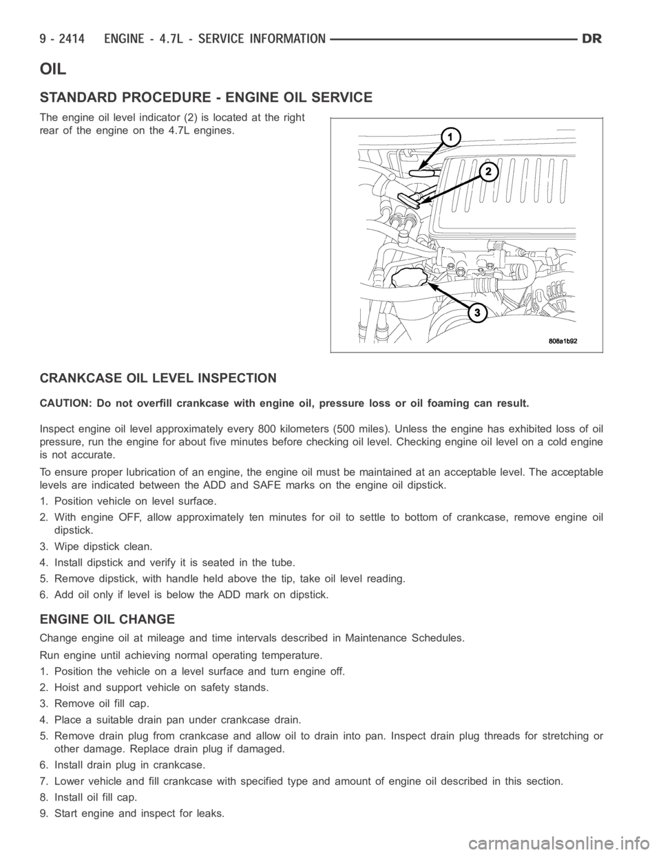
The engine oil level indicator (2) is located at the right
rear of the engine on the 4.7L engines.
CRANKCASE OIL LEVEL INSPECTION
CAUTION: Do not overfill crankcase with engine oil, pressure loss or oil foaming can result.
Inspect engine oil level approximately every 800 kilometers (500 miles).Unless the engine has exhibited loss of oil
pressure, run the engine for about five minutes before checking oil level.Checking engine oil level on a cold engine
is not accurate.
To ensure proper lubrication of an engine, the engine oil must be maintained at an acceptable level. The acceptable
levels are indicated between the ADD and SAFE marks on the engine oil dipstick.
1. Position vehicle on level surface.
2. With engine OFF, allow approximately ten minutes for oil to settle to bottom of crankcase, remove engine oil
dipstick.
3. Wipe dipstick clean.
4. Install dipstick and verify it is seated in the tube.
5. Remove dipstick, with handle held above the tip, take oil level reading.
6. Add oil only if level is below the ADD mark on dipstick.
ENGINE OIL CHANGE
Change engine oil at mileage and time intervals described in Maintenance Schedules.
Run engine until achieving normal operating temperature.
1. Position the vehicle on a level surface and turn engine off.
2. Hoist and support vehicle on safety stands.
3. Remove oil fill cap.
4. Place a suitable drain pan under crankcase drain.
5. Remove drain plug from crankcase and allow oil to drain into pan. Inspectdrain plug threads for stretching or
other damage. Replace drain plug if damaged.
6. Install drain plug in crankcase.
7. Lower vehicle and fill crankcase with specified type and amount of engine oil described in this section.
8. Install oil fill cap.
9. Start engine and inspect for leaks.
Page 1732 of 5267
MANIFOLD - INTAKE
DESCRIPTION
The intake manifold is made of a composite material and features long runners which maximizes low end torque.
The intake manifold uses single plane sealing which consist of eight individual press in place port gaskets to prevent
leaks. Eight studs and two bolts are used to fasten the intake to the head.
DIAGNOSIS AND TESTING - INTAKE MANIFOLD LEAKAGE
An intake manifold air leak is characterized by lower than normal manifoldvacuum. Also, one or more cylinders may
not be functioning.
WARNING: USE EXTREME CAUTION WHEN THE ENGINE IS OPERATING. DO NOT STAND IN ADIRECT LINE
WITH THE FAN. DO NOT PUT YOUR HANDS NEAR THE PULLEYS, BELTS OR THE FAN. DO NOT WEAR
LOOSE CLOTHING.
1. Start the engine.
2. Spray a small stream of water at the suspected leak area.
3. If a change in RPM is observed the area of the suspected leak has been found.
4. Repair as required.
REMOVAL
1. Disconnect negative cable from battery.
2. Remove resonator assembly and air inlet hose.
3. Disconnect throttle and speed control cables.
4. Disconnect electrical connectors for the following components:
Manifold Absolute Pressure (MAP) Sensor
Intake Air Temperature (IAT) Sensor
Throttle Position (TPS) Sensor
Coolant Temperature (CTS) Sensor
Idle Air Control (IAC) Motor
5. Disconnect brake booster hose and positive crankcase ventilation (PCV)hose.
6. Disconnect generator electrical connections.
7. Disconnect air conditioning compressor electrical connections.
8. Disconnect left and right radio suppressor straps.
9. Disconnect and remove ignition coil towers (Refer to 8 - ELECTRICAL/IGNITION CONTROL/IGNITION COIL -
REMOVAL).
10. Remove top oil dipstick tube retaining bolt and ground strap.
11. Bleed fuel system (Refer to 14 - FUEL SYSTEM/FUEL DELIVERY - STANDARD PROCEDURE).
12. Remove fuel rail (Refer to 14 - FUEL SYSTEM/FUEL DELIVERY/FUEL RAIL - REMOVAL).
13. Remove throttle body assembly and mounting bracket.
14. Drain cooling system below coolant temperature level (Refer to 7 - COOLING - STANDARD PROCEDURE).
Page 1734 of 5267
INSTALLATION
1. Install intake manifold gaskets.
2. Position intake manifold.
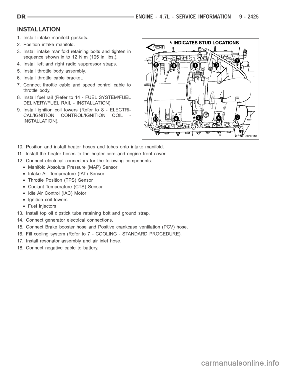
3. Install intake manifold retaining bolts and tighten in
sequence shown in to 12 Nꞏm (105 in. lbs.).
4. Install left and right radio suppressor straps.
5. Install throttle body assembly.
6. Install throttle cable bracket.
7. Connect throttle cable and speed control cable to
throttle body.
8. Install fuel rail (Refer to 14 - FUEL SYSTEM/FUEL
DELIVERY/FUEL RAIL - INSTALLATION).
9. Install ignition coil towers (Refer to 8 - ELECTRI-
CAL/IGNITION CONTROL/IGNITION COIL -
INSTALLATION).
10. Position and install heater hoses and tubes onto intake manifold.
11. Install the heater hoses to the heater core and engine front cover.
12. Connect electrical connectors for the following components:
Manifold Absolute Pressure (MAP) Sensor
Intake Air Temperature (IAT) Sensor
Throttle Position (TPS) Sensor
Coolant Temperature (CTS) Sensor
Idle Air Control (IAC) Motor
Ignition coil towers
Fuel injectors
13. Install top oil dipstick tube retaining bolt and ground strap.
14. Connect generator electrical connections.
15. Connect Brake booster hose and Positive crankcase ventilation (PCV) hose.
16. Fill cooling system (Refer to 7 - COOLING - STANDARD PROCEDURE).
17. Install resonator assembly and air inlet hose.
18. Connect negative cable to battery.
Page 1761 of 5267
Ensurethebatteryiscompletelychargedandtheenginestartermotorisingood operating condition. Otherwise the
indicated compression pressures may not be valid for diagnosis purposes.
1. Clean the spark plug recesses with compressed air.
2. Remove the spark plugs.
3. Disable the fuel system (Refer to 14 - FUEL SYSTEM/FUEL DELIVERY - DESCRIPTION).
4. Remove the ASD relay (Refer to 8 - ELECTRICAL/IGNITION CONTROL/AUTO SHUTDOWNRELAY-
REMOVAL).
5. Insert a compression pressure gauge and rotate the engine with the engine starter motor for three revolutions.
6. Record the compression pressure on the 3rd revolution. Continue the test for the remaining cylinders.
7. (Refer to 9 - ENGINE - SPECIFICATIONS) for the correct engine compression pressures.
DIAGNOSIS AND TESTING - CYLINDERCOMBUSTION PRESSURE LEAKAGE
The combustion pressure leakage test provides an accurate means for determining engine condition.
Combustion pressure leakage testing will detect:
Exhaust and intake valve leaks (improper seating).
Leaks between adjacent cylinders or into water jacket.
Any causes for combustion/compression pressure loss.
1. Check the coolant level and fill as required. DO NOT install the radiatorcap.
2. Start and operate the engine until it attains normal operating temperature, then turn the engine OFF.
3. Remove the spark plugs.
4. Remove the oil filler cap.
5. Remove the air cleaner hose.
6. Calibrate the tester according to the manufacturer’s instructions. The shop air source for testing should maintain
483 kPa (70 psi) minimum, 1,379 kPa (200 psi) maximum and 552 kPa (80 psi) recommended.
7. Perform the test procedures on each cylinder according to the tester manufacturer’s instructions. Set piston of
cylinder to be tested at TDC compression,While testing, listen for pressurized air escaping through the throttle
body, tailpipe and oil filler cap opening. Check for bubbles in the radiator coolant.
All gauge pressure indications should be equal, with no more than 25% leakage.
FOR EXAMPLE:At 552 kPa (80 psi) input pressure, a minimum of 414 kPa (60 psi) should be maintained in the
cylinder.
Refer to CYLINDER COMBUSTION PRESSURE LEAKAGE DIAGNOSIS CHART .
CYLINDER COMBUSTION PRESSURE LEAKAGE DIAGNOSIS CHART
CONDITION POSSIBLE CAUSE CORRECTION
AIR ESCAPES THROUGH
THROTTLE BODYIntake valve bent, burnt, or not
seated properlyInspect valve and valve seat.
Reface or replace, as necessary.
Inspect valve springs. Replace as
necessary.
AIR ESCAPES THROUGH
TAILPIPEExhaust valve bent, burnt, or not
seated properlyInspect valve and valve seat.
Reface or replace, as necessary.
Inspect valve springs. Replace as
necessary.
AIR ESCAPES THROUGH
RADIATORHead gasket leaking or cracked
cylinder head or blockRemove cylinder head and inspect.
Replace defective part
MORE THAN 50% LEAKAGE
FROM ADJACENT CYLINDERSHead gasket leaking or crack in
cylinder head or block between
adjacent cylindersRemove cylinder head and inspect.
Replace gasket, head, or block as
necessary
Page 1852 of 5267
TAPPETS - HYDRAULIC ROLLER
DIAGNOSIS AND TESTING - HYDRAULIC TAPPETS
Before disassembling any part of the engine to correct tappet noise, checkthe oil pressure. If vehicle has no oil
pressure gauge, install a reliable gauge at the pressure sending-unit. The pressure should be between 207-552 kPa
(30-70 psi) at 3,000 RPM.
Check the oil level after the engine reaches normal operating temperature. Allow 5 minutes to stabilize oil level,
check dipstick. The oil level in the pan should never be above the FULL mark or below the ADD OIL mark on
dipstick. Either of these two conditions could be responsible for noisy tappets.
OIL LEVEL
HIGH
If oil level is above the FULL mark, it is possible for the connecting rods todip into the oil. With the engine running,
this condition could create foam in the oil pan. Foam in oil pan would be fed to the hydraulic tappets by the oil pump
causing them to lose length and allow valves to seat noisily.
LOW
Low oil level may allow oil pump to take in air. When air is fed to the tappets,they lose length, which allows valves
to seat noisily. Any leaks on intake side of oil pump through which air can bedrawn will create the same tappet
action. Check the lubrication system from the intake strainer to the pump cover, including the relief valve retainer
cap. When tappet noise is due to aeration, it may be intermittent or constant, and usually more than one tappet will
be noisy. When oil level and leaks have been corrected, operate the engine at fast idle. Run engine for a sufficient
time to allow all of the air inside the tappets to be bled out.
TAPPET NOISE DIAGNOSIS
1. To determine source of tappet noise, crank over engine with cylinder head covers removed.
2. Feel each valve spring or rocker arm to detect noisy tappet. The noisy tappet will cause the affected spring
and/or rocker arm to vibrate or feel rough in operation.
NOTE: Worn valve guides or cocked springs are sometimes mistaken for noisytappets. If such is the case,
noise may be dampened by applying side thrust on the valve spring. If noise is not appreciably reduced, it
can be assumed the noise is in the tappet. Inspect the rocker arm push rod sockets and push rod ends for
wear.
3. Valve tappet noise ranges from light noise to a heavy click. A light noiseis usually caused by excessive leak-
down around the unit plunger, or by the plunger partially sticking in the tappet body cylinder. The tappet should
be replaced. A heavy click is caused by a tappet check valve not seating, or by foreign particles wedged between
the plunger and the tappet body. This will cause the plunger to stick in the down position. This heavy click will be
accompanied by excessive clearance between the valve stem and rocker arm as valve closes. In either case,
tappet assembly should be removed for inspection and cleaning.
4. The valve train generates a noise very much like a light tappet noise during normal operation. Care must be
taken to ensure that tappets are making the noise. If more than one tappet seems to be noisy, it’s probably not
the tappets.
REMOVAL
1. Disconnect the negative cable from the battery.
2. Remove the air cleaner (Refer to 9 - ENGINE/AIR INTAKE SYSTEM - REMOVAL).
3. Remove intake manifold (Refer to 9 - ENGINE/MANIFOLDS/INTAKE MANIFOLD-REMOVAL).
4. Remove cylinder head cover (Refer to 9 - ENGINE/CYLINDER HEAD/CYLINDERHEAD COVER(S) -
REMOVAL).
5. Remove rocker arm assembly and push rods (Refer to 9 - ENGINE/CYLINDER HEAD/ROCKER ARM /
ADJUSTER ASSY - REMOVAL). Identify push rods to ensure installation in original location.
6. Remove the cylinder head (Refer to 9 - ENGINE/CYLINDER HEAD - REMOVAL).
Page 1877 of 5267
OIL
STANDARD PROCEDURE - ENGINE OIL SERVICE
The engine oil level indicator is located at the left hand of the engine on the 5.7L engines.
CRANKCASE OIL LEVEL INSPECTION
CAUTION: Do not overfill crankcase with engine oil, pressure loss or oil foaming can result.
Inspect engine oil level approximately every 800 kilometers (500 miles).Unless the engine has exhibited loss of oil
pressure, run the engine for about ten minutes before checking oil level. Checking engine oil level on a cold engine
is not accurate.
To ensure proper lubrication of an engine, the engine oil must be maintained at an acceptable level. The acceptable
levels are indicated between the ADD and SAFE marks on the engine oil dipstick.
1. Position vehicle on level surface.
2. With engine OFF, allow approximately five minutes for oil to settle to bottom of crankcase, remove engine oil
dipstick.
3. Wipe dipstick clean.
4. Install dipstick and verify it is seated in the tube.
5. Remove dipstick, with handle held above the tip, take oil level reading.
6. Add oil only if level is below the ADD mark on dipstick.
ENGINE OIL CHANGE
Change engine oil at mileage and time intervals described in Maintenance Schedules (Refer to LUBRICATION &
MAINTENANCE/MAINTENANCESCHEDULES - DESCRIPTION).
Run engine until achieving normal operating temperature.
1. Position the vehicle on a level surface and turn engine off.
2. Hoist and support vehicle on safety stands.
3. Remove oil fill cap.
4. Place a suitable drain pan under crankcase drain.
5. Remove drain plug from crankcase and allow oil to drain into pan. Inspectdrain plug threads for stretching or
other damage. Replace drain plug if damaged.
6. Install drain plug in crankcase. Torque to 34 Nꞏm ( 25 ft. lbs.).
7. Lower vehicle and fill crankcase with specified type and amount of engine oil described in this section.
8. Install oil fill cap.
9. Start engine and inspect for leaks.
10. Stop engine and inspect oil level.
USED ENGINE OIL DISPOSAL
Care should be exercised when disposing used engine oil after it has been drained from a vehicle engine. Refer to
the WARNING at beginning of this section.
Page 1907 of 5267
CONDITION POSSIBLE CAUSES CORRECTION
11. Directed piston cooling nozzles
under piston, bad fit into main
carrier.11. Check directed piston cooling nozzles
position.
12. Loose oil rifle plug with saddle-jet
style nozzles12.Tighten oil rifle plug.
13. Loose directed piston cooling
nozzle.13. Tighten directed piston cooling nozzle.
14. Both J-jet and saddle jet style
cooling nozzle installed.14. Install correct style jet.
LUBRICATING OIL
PRESSURE TOO HIGH1. Pressure switch/gauge not
operating properly.1. Verify pressure switch is functioning
correctly. If not, replace switch/gauge.
ENGINE BREATHER
RESTRICTED2. Engine running too cold. 2. Refer to Coolant Temperature Below
Normal (Refer to 7 - COOLING -
DIAGNOSIS AND TESTING).
3. Oil viscosity too thick. 3. Make sure the correct oil is being used.
(Refer to LUBRICATION &
MAINTENANCE/FLUID TYPES -
DESCRIPTION).
4. Oil pressure relief valve stuck
closed or binding4. Check and replace valve.
LUBRICATING OIL LOSS 1. External leaks. 1. Visually inspect for oil leaks.Repair as
required.
2. Crankcase being overfilled. 2. Verify that the correct dipstick is being
used.
3. Incorrect oil specification or
viscosity.3. (a) Make sure the correct oil is being
used (Refer to LUBRICATION &
MAINTENANCE/FLUID TYPES -
DESCRIPTION).
(b) Look for reduced viscosity from dilution
with fuel.
(c) Review/reduce oil change intervals.
4. Oil cooler leak 4. Check and replace the oil cooler.
5. High blow-by forcing oil out the
breather.5. Check the breather tube area for signs of
oil loss. Perform the required repairs.
6. Turbocharger leaking oil to the air
intake.6. Inspect the air ducts for evidence of oil
transfer. Repair as required.
COMPRESSION KNOCKS 1. Air in the fuel system. 1. Identify location of air leak and repair. Do
not bleed high pressure fuel system.
2. Poor quality fuel or water/gasoline
contaminated fuel.2. Verify by operating from a temporary
tank with good fuel. Clean and flush the
fuel tank. Replace fuel/water separator filter.
3. Engine overloaded. 3. Verify the engine load rating is not being
exceeded.
4. Improperly operating injectors. 4. Check and replace misfiring/inoperative
injectors.
EXCESSIVE VIBRATION 1. Loose or broken engine mounts. 1. Replace engine mounts.
2. Damaged fan or improperly
operating accessories.2. Check and replace the vibrating
components.
Page 1910 of 5267

EXCESSIVE WHITE SMOKE
POSSIBLE CAUSE CORRECTION
Fuel filter plugged. Refer to Powertrain Diagnostic Manual for fuel system
testing.
Fuel grade not correct or fuel quality is poor. Temporarily change fuel brands and note condition.
Change brand if necessary.
Fuel heater element or fuel heater temperature sensor
malfunctioning. This will cause wax type build-up in fuel
filter.Refer to Fuel Heater Testing (Refer to 14 - FUEL
SYSTEM/FUEL DELIVERY/FUEL HEATER -
DIAGNOSIS AND TESTING).
Fuel injector malfunctioning. A DTC should have been set. Perform “Cylinder
Performance Test
orCylinder cutout Testusing DRB
scan tool to isolate individual cylinders. Also refer to
Powertrain Diagnostic Procedures Information and,
(Refer to 14 - FUEL SYSTEM/FUEL INJECTION/FUEL
INJECTOR - DIAGNOSIS AND TESTING).
Fuel injector hold-downs loose. Torque to specifications.
Fuel injector protrusion not correct. Check washer (shim) at bottom of fuel injector for
correct thickness. (Referto 14 - FUEL SYSTEM/FUEL
INJECTION/FUEL INJECTOR - INSTALLATION)
Fuel injection pump malfunctioning. A DTC should have been set. Refer to Powertrain
Diagnostic Procedures Information.
Fuel supply side restriction. Refer to Powertrain Diagnostic Manual for fuel system
testing.
Fuel transfer (lift) pump malfunctioning. A DTC may have been set. Refer toPowertrain
Diagnostic Procedures Information.
Intake/Exhaust valve adjustments not correct (too tight). (Refer to 9 - ENGINE/CYLINDER HEAD/INTAKE/
EXHAUST VALVES & SEATS - STANDARD
PROCEDURE).
Intake manifold air temperature sensor malfunctioning. A DTC should havebeen set. Refer to Powertrain
Diagnostic Procedures Information.
Intake manifold heater circuit not functioning correctly in
cold weather.A DTC should have been set. Refer to Powertrain
Diagnostic Procedures Information. Also check heater
elements for correct operation.
Intake manifold heater elements not functioning
correctly in cold weather.A DTC should have been set if heater elements are
malfunctioning. Refer to Powertrain Diagnostic
Procedures Information.
Internal engine damage (scuffed cylinder). Analyze engine oil and inspect oil filter to locate area of
probable damage.
Restriction in fuel supply side of fuel system. Refer to Powertrain Diagnostic Manual for fuel system
testing.
EXCESSIVE BLUE SMOKE
POSSIBLE CAUSE CORRECTION
Dirty air cleaner or restricted turbocharger intake duct. Check Filter Minder
at air filter housing. (Refer to 9 -
ENGINE/AIR INTAKE SYSTEM/AIR CLEANER
ELEMENT - REMOVAL).
Air leak in boost system between turbocharger
compressor outlet and intake manifold.Service air charge system..
Obstruction in exhaust manifold. Remove exhaust manifold and inspect forblockage
(Refer to 9 - ENGINE/MANIFOLDS/EXHAUST
MANIFOLD - REMOVAL).