2006 DODGE RAM SRT-10 oil temperature
[x] Cancel search: oil temperaturePage 1440 of 5267
When Monitored:
With the ignition key on and the engine speed greater than 0 RPM.
Set Condition:
When the PCM regulates the generator field and there are no detected field problems, but the voltage output
does not decrease.
Possible Causes
(K20) GENERATOR FIELD CONTROL CIRCUIT SHORTED TO GROUND
GENERATOR FIELD COIL SHORTED TO GROUND
BATTERY TEMPERATURE SENSOR
PCM
Always perform the Pre-Diagnostic Troubleshooting procedure before proceeding. (Refer to 9 - ENGINE -
DIAGNOSIS AND TESTING)
Diagnostic Test
1.CHARGING SYSTEM OPERATION
NOTE: Battery must be fully charged and be capable of passing a load test.
NOTE: Generator Belt tension and condition must be checked before continuing.
Ignition on, engine not running.
With the scan tool, read DTCs and the related Freeze Frame data then clear theDTCs.
With scan tool, actuate the Generator Field Driver.
With a 12-volt test light connected to ground, backprobe the (K20) Gen Field Control circuit in the back of Generator
Field harness connector.
Does the test light illuminate brightly and flash?
Ye s>>
Go To 2
No>>
Refer to the INTERMITTENT CONDITION Diagnostic Procedure.
Perform the POWERTRAIN VERIFICATION TEST. (Refer to 9 - ENGINE - STANDARD PROCEDURE)
2.(K20) GEN FIELD CONTROL CIRCUIT SHORTED TO GROUND
Turn the ignition off.
Disconnect the C2 PCM harness connector.
Disconnect the Generator Field Harness connector.
Carefully inspect the related connectors for corrosion or spread termi-
nals before continuing.
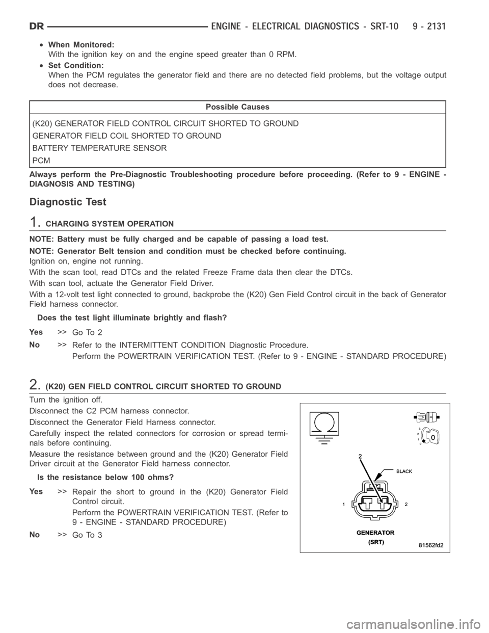
Measure the resistance between ground and the (K20) Generator Field
Driver circuit at the Generator Field harness connector.
Istheresistancebelow100ohms?
Ye s>>
Repair the short to ground in the (K20) Generator Field
Control circuit.
Perform the POWERTRAIN VERIFICATION TEST. (Refer to
9 - ENGINE - STANDARD PROCEDURE)
No>>
Go To 3
Page 1441 of 5267
3.GENERATOR FIELD COIL SHORTED TO GROUND
Measure the resistance between ground and the Generator Field terminals on the Generator.
Istheresistancebelow100ohms?
Ye s>>
Replace or repair the Generator Field Coil for a short to ground.
Perform the POWERTRAIN VERIFICATION TEST. (Refer to 9 - ENGINE - STANDARD PROCEDURE)
No>>
Go To 4
4.BATTERY TEMPERATURE SENSOR
Connect the PCM harness connectors and the Generator harness connector.
Ignition on, engine not running.
With the scan tool in Inputs/Outputs, read the Batt Temp Sensor value.
Using a thermometer measure under hood temperature near Battery tray.
Is the temperature within 10 deg of Battery temperature?
Ye s>>
Go To 5
No>>
Replace the Battery Temperature Sensor.
Perform the POWERTRAIN VERIFICATION TEST. (Refer to 9 - ENGINE - STANDARD PROCEDURE)
5.PCM
NOTE: Before continuing, check the PCM harness connector terminals for corrosion, damage, or terminal
push out. Repair as necessary.
Using the schematics as a guide, inspect the wire harness and connectors. Pay particular attention to all Power and
Ground circuits.
If there are no possible causes remaining, view repair.
Repair
Replace and program the Powertrain Control Module per Service Information.
Perform the POWERTRAIN VERIFICATION TEST. (Refer to 9 - ENGINE - STANDARD PROCEDURE)
Page 1451 of 5267
When Monitored:
With the ignition key on and the engine running over 1500 RPM after 25 seconds.
Set Condition:
When the PCM regulates the generator field and there are no detected field problems, but the voltage output
does not increase.
Possible Causes
BATTERY TEMPERATURE SENSOR
RESISTANCE IN THE BATTERY POSITIVE CIRCUIT
(K125) GENERATOR FIELD SOURCE CIRCUIT OPEN
RESISTANCE IN THE GENERATOR GROUND
(K125) GENERATOR FIELD SOURCE CIRCUIT SHORTED TO GROUND
(K20) GENERATOR FIELD CONTROL CIRCUIT OPEN
RESISTANCE IN THE GENERATOR FIELD COIL
PCM
Always perform the Pre-Diagnostic Troubleshooting procedure before proceeding. (Refer to 9 - ENGINE -
DIAGNOSIS AND TESTING)
Diagnostic Test
1.CHARGING VOLTAGE BELOW 15.1 VOLTS
Turn the ignition off.
NOTE: Battery must be fully charged and capable of passing a battery load test.
NOTE: Generator Belt tension and condition must be checked before continuing.
NOTE: Inspect the vehicle for any aftermarket accessories that may exceedthe maximum Generator output.
WARNING: When the engine is operating, do not stand in direct line of the fan. Do not put your hands near
the pulley, belts, or fan. Do no wear loose clothing.
Start the engine.
Record all DTCs and the related Freeze Frame data.
With the scan tool, read the target charging voltage.
Is the target charging voltage above 15.1 volts?
Ye s>>
Refer to the INTERMITTENT CONDITION Diagnostic Procedure.
Perform the POWERTRAIN VERIFICATION TEST. (Refer to 9 - ENGINE - STANDARD PROCEDURE)
No>>
Go To 2
2.BATTERY TEMPERATURE SENSOR
Turn the ignition off.
NOTE: Generator Belt tension and condition must be checked before continuing.
Start the engine.
Allow the engine to reach normal operating temperature.
With the scan tool in sensors, read the Battery Temp Sensor value.
Using a Thermometer, measure under hood temperature.
Is the temperature within 10° F of Battery temperature?
Ye s>>
Go To 3
No>>
Replace the Battery Temperature Sensor.
Perform the POWERTRAIN VERIFICATION TEST. (Refer to 9 - ENGINE - STANDARD PROCEDURE)
Page 1474 of 5267
4.RESISTANCE IN THE GENERATOR GROUND
Start the engine.
Warm the engine to operating temperature.
CAUTION: Make sure all wires are clear of the engine’s moving parts.
Measure the voltage between the Generator case and Battery Negative Post.
Is the voltage above 0.1 of a volt?
Ye s>>
Repair the excessive resistance in the Generator Ground circuit between the Generator Case and Bat-
tery Ground side.
Perform the POWERTRAIN VERIFICATION TEST. (Refer to 9 - ENGINE - STANDARD PROCEDURE)
No>>
Go To 5
5.GENERATOR FIELD COIL HIGH RESISTANCE
Turn the ignition off.
Disconnect the Generator Field harness connector at back of the Generator.
Measure resistance across the Generator Field Terminals at the Generator.
Is the resistance above 15 ohms?
Ye s>>
Replace or repair the Generator as necessary.
Perform the POWERTRAIN VERIFICATION TEST. (Refer to 9 - ENGINE - STANDARD PROCEDURE)
No>>
Go To 6
6.(K20) GEN FIELD CONTROL CIRCUIT OPEN
Disconnect the C3 PCM harness connector.
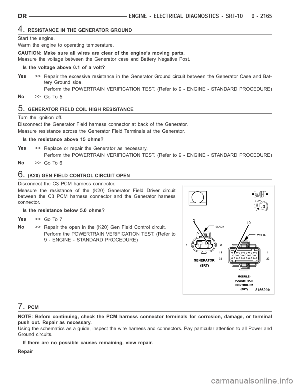
Measure the resistance of the (K20) Generator Field Driver circuit
between the C3 PCM harness connector and the Generator harness
connector.
Is the resistance below 5.0 ohms?
Ye s>>
Go To 7
No>>
Repair the open in the (K20) Gen Field Control circuit.
Perform the POWERTRAIN VERIFICATION TEST. (Refer to
9 - ENGINE - STANDARD PROCEDURE)
7.PCM
NOTE: Before continuing, check the PCM harness connector terminals for corrosion, damage, or terminal
push out. Repair as necessary.
Using the schematics as a guide, inspect the wire harness and connectors. Pay particular attention to all Power and
Ground circuits.
If there are no possible causes remaining, view repair.
Repair
Page 1494 of 5267
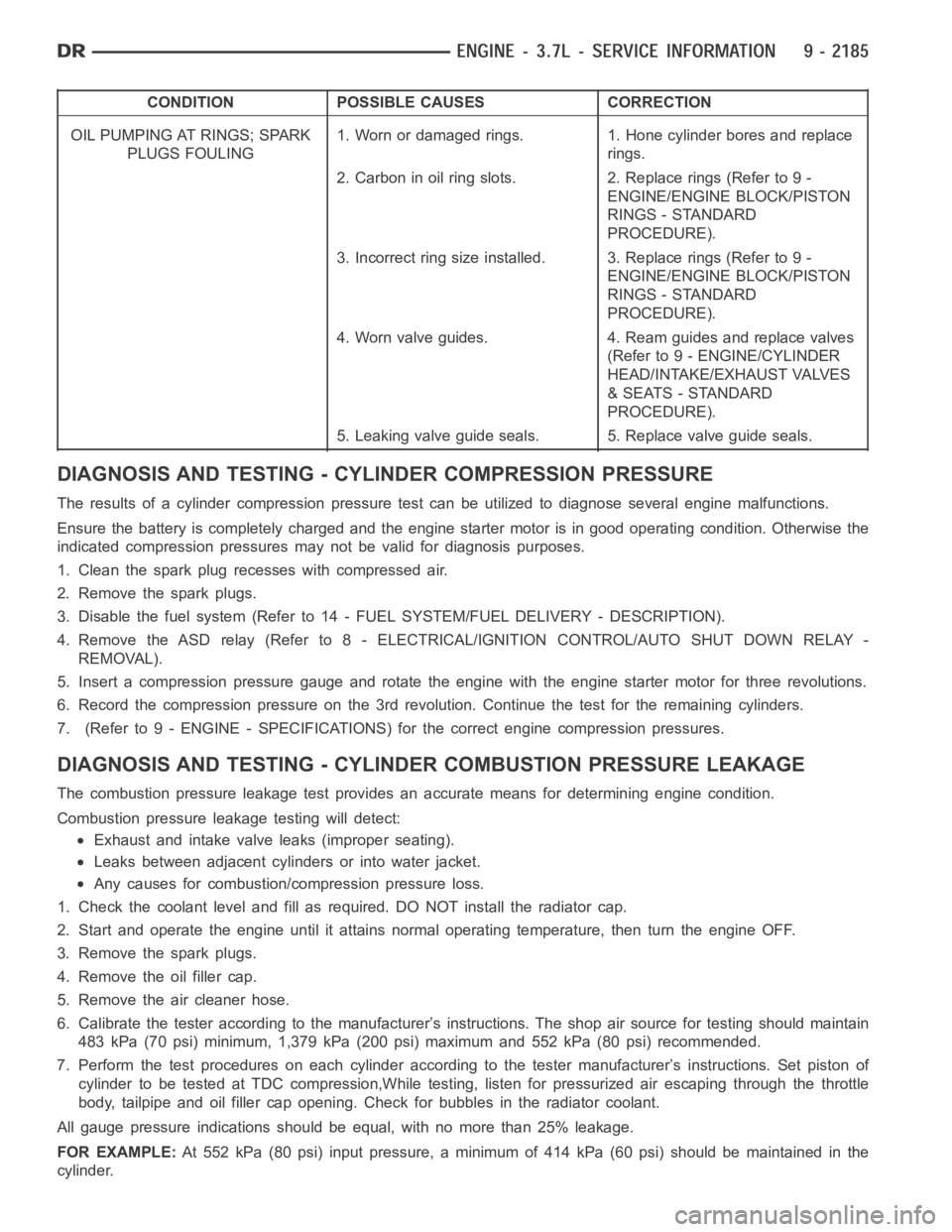
CONDITION POSSIBLE CAUSES CORRECTION
OIL PUMPING AT RINGS; SPARK
PLUGS FOULING1. Worn or damaged rings. 1. Hone cylinder bores and replace
rings.
2. Carbon in oil ring slots. 2. Replace rings (Refer to 9 -
ENGINE/ENGINE BLOCK/PISTON
RINGS - STANDARD
PROCEDURE).
3. Incorrect ring size installed. 3. Replace rings (Refer to 9 -
ENGINE/ENGINE BLOCK/PISTON
RINGS - STANDARD
PROCEDURE).
4. Worn valve guides. 4. Ream guides and replace valves
(Refer to 9 - ENGINE/CYLINDER
HEAD/INTAKE/EXHAUST VALVES
& SEATS - STANDARD
PROCEDURE).
5. Leaking valve guide seals. 5. Replace valve guide seals.
DIAGNOSIS AND TESTING - CYLINDER COMPRESSION PRESSURE
The results of a cylinder compressionpressure test can be utilized to diagnose several engine malfunctions.
Ensurethebatteryiscompletelychargedandtheenginestartermotorisingood operating condition. Otherwise the
indicated compression pressures may not be valid for diagnosis purposes.
1. Clean the spark plug recesses with compressed air.
2. Remove the spark plugs.
3. Disable the fuel system (Refer to 14 - FUEL SYSTEM/FUEL DELIVERY - DESCRIPTION).
4. Remove the ASD relay (Refer to 8 - ELECTRICAL/IGNITION CONTROL/AUTO SHUTDOWNRELAY-
REMOVAL).
5. Insert a compression pressure gauge and rotate the engine with the engine starter motor for three revolutions.
6. Record the compression pressure on the 3rd revolution. Continue the test for the remaining cylinders.
7. (Refer to 9 - ENGINE - SPECIFICATIONS) for the correct engine compression pressures.
DIAGNOSIS AND TESTING - CYLINDERCOMBUSTION PRESSURE LEAKAGE
The combustion pressure leakage test provides an accurate means for determining engine condition.
Combustion pressure leakage testing will detect:
Exhaust and intake valve leaks (improper seating).
Leaks between adjacent cylinders or into water jacket.
Any causes for combustion/compression pressure loss.
1. Check the coolant level and fill as required. DO NOT install the radiatorcap.
2. Start and operate the engine until it attains normal operating temperature, then turn the engine OFF.
3. Remove the spark plugs.
4. Remove the oil filler cap.
5. Remove the air cleaner hose.
6. Calibrate the tester according to the manufacturer’s instructions. The shop air source for testing should maintain
483 kPa (70 psi) minimum, 1,379 kPa (200 psi) maximum and 552 kPa (80 psi) recommended.
7. Perform the test procedures on each cylinder according to the tester manufacturer’s instructions. Set piston of
cylinder to be tested at TDC compression,While testing, listen for pressurized air escaping through the throttle
body, tailpipe and oil filler cap opening. Check for bubbles in the radiator coolant.
All gauge pressure indications should be equal, with no more than 25% leakage.
FOR EXAMPLE:At 552 kPa (80 psi) input pressure, a minimum of 414 kPa (60 psi) should be maintained in the
cylinder.
Page 1496 of 5267
MoparGasket Maker is an anaerobic type gasket material. The material cures in the absence of air when
squeezed between two metallic surfaces. It will not cure if left in the uncovered tube. The anaerobic material is for
use between two machined surfaces. Do not use on flexible metal flanges.
MOPAR
GASKET SEALANT
Mopar
Gasket Sealant is a slow drying, permanently soft sealer. This material isrecommended for sealing
threaded fittings and gaskets against leakage of oil and coolant. Can be used on threaded and machined parts
under all temperatures. This material is used on engines with multi-layersteel (MLS) cylinder head gaskets. This
material also will prevent corrosion. Mopar
Gasket Sealant is available in a 13 oz. aerosol can or 4oz./16 oz. can
w/applicator.
FORM-IN-PLACE GASKET AND SEALER APPLICATION
Assembling parts using a form-in-place gasket requires care but it’s easier than using precut gaskets.
Mopar
Gasket Maker material should be applied sparingly 1 mm (0.040 in.) diameter or less of sealant to one
gasket surface. Be certain the material surrounds each mounting hole. Excess material can easily be wiped off.
Components should be torqued in place within 15 minutes. The use of a locating dowel is recommended during
assembly to prevent smearing material off the location.
Mopar
Engine RTV GEN II or ATF RTV gasket material should be applied in a continuous bead approximately 3
mm (0.120 in.) in diameter. All mounting holes must be circled. For corner sealing, a 3.17 or 6.35 mm (1/8 or 1/4 in.)
drop is placed in the center of the gasket contact area. Uncured sealant maybe removed with a shop towel. Com-
ponents should be torqued in place while the sealant is still wet to the touch (within 10 minutes). The usage of a
locating dowel is recommended during assembly to prevent smearing material off the location.
Mopar
Gasket Sealant in an aerosol can should be applied using a thin, even coat sprayed completely over both
surfaces to be joined, and both sides of a gasket. Then proceed with assembly. Material in a can w/applicator can
be brushed on evenly over the sealing surfaces. Material in an aerosol can shouldbeusedonengineswithmulti-
layer steel gaskets.
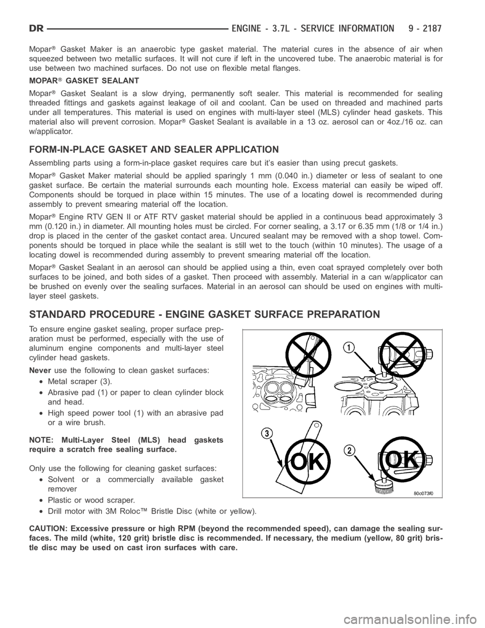
STANDARD PROCEDURE - ENGINE GASKET SURFACE PREPARATION
To ensure engine gasket sealing, proper surface prep-
aration must be performed, especially with the use of
aluminum engine components and multi-layer steel
cylinder head gaskets.
Neveruse the following to clean gasket surfaces:
Metal scraper (3).
Abrasive pad (1) or paper to clean cylinder block
and head.
High speed power tool (1) with an abrasive pad
orawirebrush.
NOTE: Multi-Layer Steel (MLS) head gaskets
require a scratch free sealing surface.
Only use the following for cleaning gasket surfaces:
Solvent or a commercially available gasket
remover
Plastic or wood scraper.
Drill motor with 3M Roloc™ Bristle Disc (white or yellow).
CAUTION: Excessive pressure or high RPM (beyond the recommended speed), can damage the sealing sur-
faces. The mild (white, 120 grit) bristle disc is recommended. If necessary, the medium (yellow, 80 grit) bris-
tle disc may be used on cast iron surfaces with care.
Page 1498 of 5267
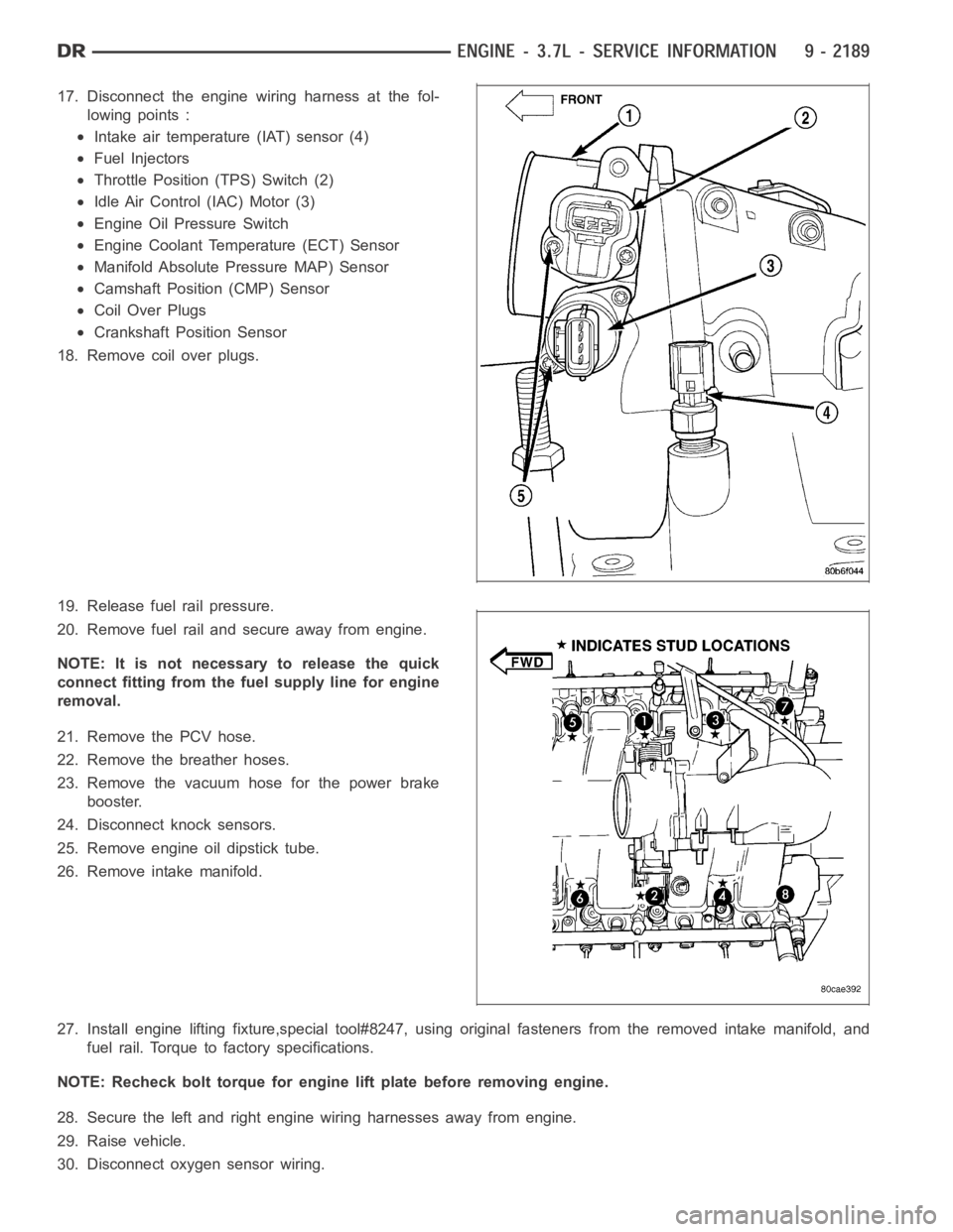
17. Disconnect the engine wiring harness at the fol-
lowing points :
Intake air temperature (IAT) sensor (4)
Fuel Injectors
Throttle Position (TPS) Switch (2)
Idle Air Control (IAC) Motor (3)
Engine Oil Pressure Switch
Engine Coolant Temperature (ECT) Sensor
Manifold Absolute Pressure MAP) Sensor
Camshaft Position (CMP) Sensor
Coil Over Plugs
Crankshaft Position Sensor
18. Remove coil over plugs.
19. Release fuel rail pressure.
20. Remove fuel rail and secure away from engine.
NOTE: It is not necessary to release the quick
connect fitting from the fuel supply line for engine
removal.
21. Remove the PCV hose.
22. Remove the breather hoses.
23. Remove the vacuum hose for the power brake
booster.
24. Disconnect knock sensors.
25. Remove engine oil dipstick tube.
26. Remove intake manifold.
27. Install engine lifting fixture,special tool#8247, using original fasteners from the removed intake manifold, and
fuel rail. Torque to factory specifications.
NOTE: Recheck bolt torque for engine lift plate before removing engine.
28. Secure the left and right engine wiring harnesses away from engine.
29. Raise vehicle.
30. Disconnect oxygen sensor wiring.
Page 1503 of 5267
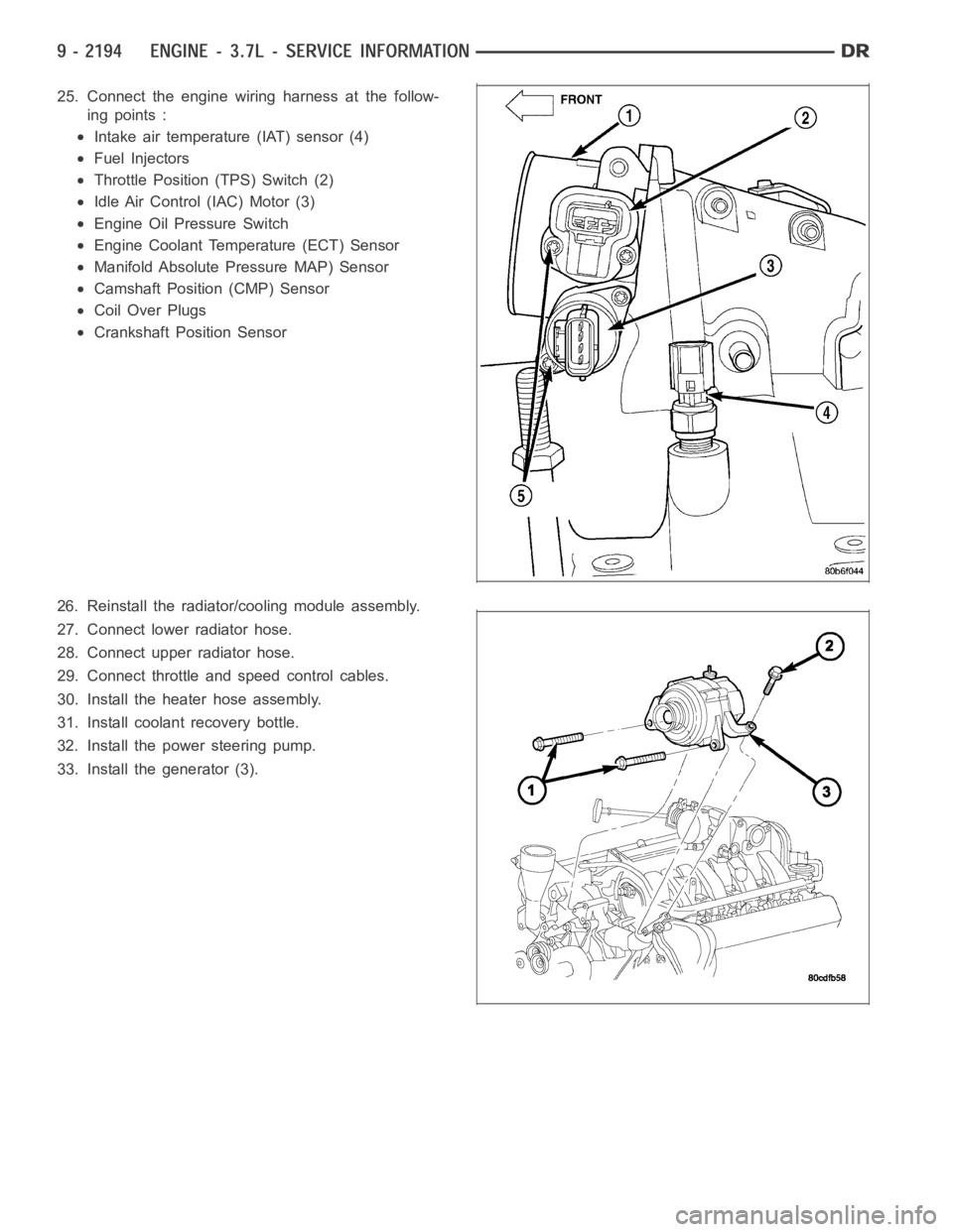
25. Connect the engine wiring harness at the follow-
ing points :
Intake air temperature (IAT) sensor (4)
Fuel Injectors
Throttle Position (TPS) Switch (2)
Idle Air Control (IAC) Motor (3)
Engine Oil Pressure Switch
Engine Coolant Temperature (ECT) Sensor
Manifold Absolute Pressure MAP) Sensor
Camshaft Position (CMP) Sensor
Coil Over Plugs
Crankshaft Position Sensor
26. Reinstall the radiator/cooling module assembly.
27. Connect lower radiator hose.
28. Connect upper radiator hose.
29. Connect throttle and speed control cables.
30. Install the heater hose assembly.
31. Install coolant recovery bottle.
32. Install the power steering pump.
33. Install the generator (3).