2006 DODGE RAM SRT-10 oil temperature
[x] Cancel search: oil temperaturePage 1913 of 5267
MoparEngine RTV GEN II is used to seal components exposed to engine oil. This material is a specially designed
black silicone rubber RTV that retains adhesion and sealing properties when exposed to engine oil. Moisture in the
air causes the material to cure. This material is available in three ounce tubes and has a shelf life of one year. After
one year this material will not properly cure. Always inspect the package for the expiration date before use.
MOPAR
AT F R T V
Mopar
ATF RTV is a specifically designed black silicone rubber RTV that retains adhesion and sealing properties
to seal components exposed to automatic transmission fluid, engine coolants, and moisture. This material is avail-
able in three ounce tubes and has a shelf life of one year. After one year thismaterial will not properly cure. Always
inspect the package for the expiration date before use.
MOPAR
GASKET MAKER
Mopar
Gasket Maker is an anaerobic type gasket material. The material cures in the absence of air when
squeezed between two metallic surfaces. It will not cure if left in the uncovered tube. The anaerobic material is for
use between two machined surfaces. Do not use on flexible metal flanges.
MOPAR
GASKET SEALANT
Mopar
Gasket Sealant is a slow drying, permanently soft sealer. This material isrecommended for sealing
threaded fittings and gaskets against leakage of oil and coolant. Can be used on threaded and machined parts
under all temperatures. This material is used on engines with multi-layersteel (MLS) cylinder head gaskets. This
material also will prevent corrosion. Mopar
Gasket Sealant is available in a 13 oz. aerosol can or 4oz./16 oz. can
w/applicator.
FORM-IN-PLACE GASKET AND SEALER APPLICATION
Assembling parts using a form-in-place gasket requires care but it’s easier than using precut gaskets.
Mopar
Gasket Maker material should be applied sparingly 1 mm (0.040 in.) diameter or less of sealant to one
gasket surface. Be certain the material surrounds each mounting hole. Excess material can easily be wiped off.
Components should be torqued in place within 15 minutes. The use of a locating dowel is recommended during
assembly to prevent smearing material off the location.
Mopar
Engine RTV GEN II or ATF RTV gasket material should be applied in a continuous bead approximately 3
mm (0.120 in.) in diameter. All mounting holes must be circled. For corner sealing, a 3.17 or 6.35 mm (1/8 or 1/4 in.)
drop is placed in the center of the gasket contact area. Uncured sealant maybe removed with a shop towel. Com-
ponents should be torqued in place while the sealant is still wet to the touch (within 10 minutes). The usage of a
locating dowel is recommended during assembly to prevent smearing material off the location.
Mopar
Gasket Sealant in an aerosol can should be applied using a thin, even coat sprayed completely over both
surfaces to be joined, and both sides of a gasket. Then proceed with assembly. Material in a can w/applicator can
be brushed on evenly over the sealing surfaces. Material in an aerosol can shouldbeusedonengineswithmulti-
layer steel gaskets.
STANDARD PROCEDURE - REPAIR DAMAGED OR WORN THREADS
CAUTION: Be sure that the tapped holes maintain the original center line.
Damaged or worn threads can be repaired. Essentially, this repair consistsof:
Drilling out worn or damaged threads.
Tapping the hole with a special Heli-Coil Tap, or equivalent.
Installing an insert into the tapped hole to bring the hole back to its original thread size.
STANDARD PROCEDURE—HYDROSTATIC LOCK
CAUTION: DO NOT use the starter motor to rotate the crankshaft. Severe damage could occur.
When an engine is suspected of hydrostatic lock (regardless of what causedthe problem), follow the steps below.
1. Disconnect the negative cable(s) from the battery.
2. Inspect air cleaner, induction system, and intake manifold to ensure system is dry and clear of foreign material.
Page 1933 of 5267
CYLINDER HEAD
DESCRIPTION
The cylinder head is constructed of cast iron and is a one piece cross flow design with four valves per cylinder. The
arrangement of two intake and two exhaust valves per cylinder allows for a centrally located injector. The cylinder
head also includes an integral intake manifold, an integral thermostat housing, and a longitudal fuel return rifle,
which exits at the rear of the head. The 24 valve design also includes integrally cast valve guides and hardened
intake and exhaust valve seat inserts.
REMOVAL
1. Disconnect battery negative cables.
2. Raise vehicle on hoist.
3. Drain engine coolant.
4. Disconnect exhaust pipe from turbocharger elbow.
5. Remove turbocharger drain tube bolts at turbocharger. Cap off ports to prevent dirt or foreign material from enter-
ing.
6. Lower vehicle.
7. Disconnect air inlet temperature/pressure sensor.
8. Remove air cleaner housing and snorkel from the vehicle. Cap off turbocharger air inlet to prevent intrusion of
dirt or foreign material.
9. Disconnect cab heater core supply and return hoses from the cylinder head and heater pipe.
10. Disconnect turbocharger oil supply line at the turbocharger end. Cap off open ports to prevent intrusion of dirt
or foreign material.
11. Remove exhaust manifold-to-cylinder head bolts, spacers, heat shield, retention straps, and cab heater plumb-
ing. Remove exhaust manifold and turbocharger from the vehicle as an assembly.
12. Remove cooling fan/drive/shroud assembly. (Refer to 7 - COOLING/ENGINE/RADIATOR FAN - REMOVAL)
13. Remove accessory drive belt (Refer to 7 - COOLING/ACCESSORY DRIVE/DRIVE BELTS - REMOVAL).
14. Remove cooling fan support from cylinder block.
15. Remove upper generator bolt, loosen lower generator bolt, and rotate generator away from cylinder head.
16. Disconnect radiator upper hose from the thermostat housing.
17. Disconnect the Intake Air Temperature/Manifold Air Pressure, and Coolant Temperature sensor connectors.
18. Remove the engine harness to cylinder head attaching bolts and P-clipsat front of head.
19. Remove the intake air grid heater wires from the grid heater.
20. Remove engine oil level indicator tube attaching bolt at fuel filter housing bracket and inlet air connection..
21. Remove the charge air cooler-to-air inlet housing pipe.
22. Remove the engine wire harness attaching bolt and wire harness push-infastener from air inlet housing.
23. Remove the air inlet housing and intake grid heater from the intake manifold cover.
24. Remove the two grid heater harness-to-cylinder head attaching bolts at front of cylinder head.
NOTE: Extreme care should be used to keep dirt/debris from entering the fuel lines. Plastic caps should be
used on the ends of the fuel lines.
25.Remove the high pressure pump to fuel rail fuel line as follows:
a. Loosen fuel line nuts at fuel pump and at fuel rail.
b. Use a back-up wrench on the fitting at the fuel pump to keep it from loosening.
26. Remove the fuel rail to cylinder head fuel lines as follows:
a. Loosen No. 6 high pressure fuel line shield and position out of way.
b. Loosen the fuel line nuts at the fuel rail and at the cylinder head. Use a back-up wrench on HPC nut.
c. Remove the fuel line bracket bolts at the intake manifold cover.
Page 1939 of 5267
d. Install fuel line brace bolts-to-intake manifold finger tight for fuellines#2thru#5.
e. Install fuel line brace nut to rear lift bracket stud, finger tight, for fuel line #6.
f. Hand tighten fuel pump to fuel rail line.
g. Torque fuel line nuts at cylinder head to 30 Nꞏm ( 22 ft. lbs.).
h. Torque fuel line nuts at fuel rail to 30 Nꞏm (22 ft. lbs.)
i. Usingabackupwrench,torquefuelpumptofuelraillineto37Nꞏm(27ft.lbs.). At injection pump.
j. Torque fuel pump to fuel rail line to 37 Nꞏm (27 ft. lbs.) at fuel rail.
k. Torque fuel drain banjo bolt at pressure limiting valve and front of fuelfilter housing to 24 Nꞏm (18 ft. lbs.).
l. Torque fuel line brace bolts to 24 Nꞏm (18 ft. lbs.).
m. Torque fuel line brace nut to 24 Nꞏm (18 ft. lbs.).
n. Torque rail bolts to 24 Nꞏm (18 ft. lbs.).
o. Connect fuel pressure sensor.
p. Torque fuel filter mounting bolts to 24 Nꞏm (18 ft. lbs.).
19. Reposition number 6 fuel line shield and torque to 43 Nꞏm (32 ft. lbs.).
20. Install the fuel filter to injection pump low pressure line. Inspect and replace sealing washers if necessary.
Torque banjo bolts to 24 Nꞏm (18 ft. lbs.).
21. Connect fuel return line at back of cylinder head hand tight.
22. Connect fuel return line at filter housing hand tight.
23. Torque banjo connections at cylinder head and fuel filter housing to 24Nꞏm (18 ft. lbs.)
24. Install bracket to rear of filter housing. Torque to 24 Nꞏm (18 ft. lbs.).
25. Using new gaskets, install the intake grid heater and air inlet housing. Torque bolts to 24 Nꞏm (18 ft. lbs.).
26. Install wire harness P-clip and push on clip to air inlet housing.
27. Connect engine oil level indicator tube at fuel filter housing and at air inlet housing.
28. Install the charge air cooler-to-air inlet housing duct assembly. Torque all clamps to 11 Nꞏm (100 in. lbs.).
29. Connect intake grid heater wires.
30. Secure engine harness to front of cylinder head with bolt at four locations.
31. Connect engine coolant temperature sensor connector.
32. Connect radiator upper hose to thermostat housing.
33. Rotate generator into position. Install upper bolt and torque upper and lower bolts.
34. Install wire harness push-on clip below bracket.
35. Install wire harness P-clip to top of bracket.
36. Install fan support and torque to 32 Nꞏm (24 ft. lbs.).
37. Install cooling fan/drive refer to (Refer to 7 - COOLING/ENGINE/RADIATOR FAN - INSTALLATION).
38. Install accessory drive belt (Refer to 7 - COOLING/ACCESSORY DRIVE/DRIVE BELTS - INSTALLATION).
39. Install exhaust manifold/turbocharger assembly, using new gaskets.Start all bolts/spacers by hand. Starting
from the center bolts out, Torque bolts to 43 Nꞏm (32 ft. lbs.), then retorque from the center out again.
40. Install exhaust manifold heat shield to exhaust manifold studs. Install retaining nuts.Torque to 24 Nꞏm (18 ft.
lbs.).
41. Install exhaust bolt retention straps across cylinders 5 & 6.
42. Using a new gasket, connect the turbocharger oil drain tube. Torque to 24Nꞏm(18ft.lbs.).
43. Perform the turbocharger pre-lube procedure. (Refer to 11 - EXHAUST SYSTEM/TURBOCHARGER SYSTEM/
TURBOCHARGER - INSTALLATION)
44. Connect the turbocharger oil supply line. Torque to 24 Nꞏm (18 ft. lbs.).
45. Install air cleaner housing and duct.
46. Connect air inlet temperature/pressure sensor.
47. Raise vehicle on hoist.
Page 1962 of 5267
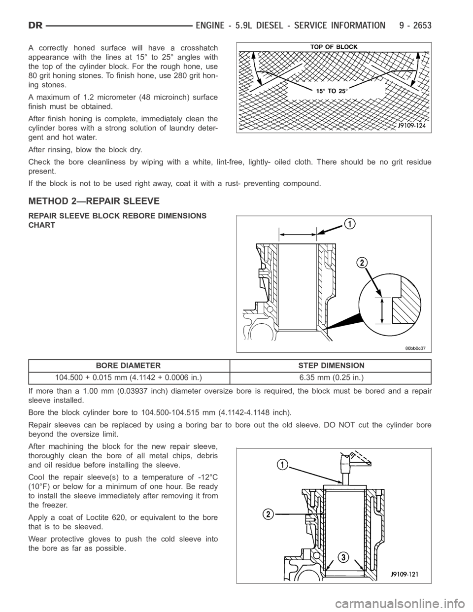
A correctly honed surface will have a crosshatch
appearance with the lines at 15° to 25° angles with
the top of the cylinder block. For the rough hone, use
80 grit honing stones. To finish hone, use 280 grit hon-
ing stones.
A maximum of 1.2 micrometer (48 microinch) surface
finish must be obtained.
After finish honing is complete, immediately clean the
cylinder bores with a strong solution of laundry deter-
gent and hot water.
After rinsing, blow the block dry.
Check the bore cleanliness by wiping with a white, lint-free, lightly- oiled cloth. There should be no grit residue
present.
If the block is not to be used right away, coat it with a rust- preventing compound.
METHOD 2—REPAIR SLEEVE
REPAIR SLEEVE BLOCK REBORE DIMENSIONS
CHART
BORE DIAMETER STEP DIMENSION
104.500 + 0.015 mm (4.1142 + 0.0006 in.) 6.35 mm (0.25 in.)
If more than a 1.00 mm (0.03937 inch) diameter oversize bore is required, the block must be bored and a repair
sleeve installed.
Bore the block cylinder bore to 104.500-104.515 mm (4.1142-4.1148 inch).
Repair sleeves can be replaced by using a boring bar to bore out the old sleeve. DO NOT cut the cylinder bore
beyond the oversize limit.
After machining the block for the new repair sleeve,
thoroughly clean the bore of all metal chips, debris
and oil residue before installing the sleeve.
Cool the repair sleeve(s) to a temperature of -12°C
(10°F) or below for a minimum of one hour. Be ready
to install the sleeve immediately after removing it from
the freezer.
Apply a coat of Loctite 620, or equivalent to the bore
that is to be sleeved.
Wear protective gloves to push the cold sleeve into
the bore as far as possible.
Page 1973 of 5267
CRANKSHAFT & GEAR
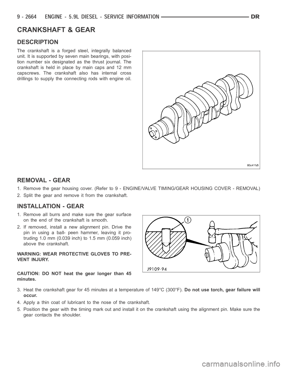
DESCRIPTION
The crankshaft is a forged steel, integrally balanced
unit. It is supported by seven main bearings, with posi-
tion number six designated as the thrust journal. The
crankshaft is held in place by main caps and 12 mm
capscrews. The crankshaft also has internal cross
drillings to supply the connecting rods with engine oil.
REMOVAL - GEAR
1. Remove the gear housing cover. (Refer to 9 - ENGINE/VALVE TIMING/GEAR HOUSING COVER - REMOVAL)
2. Split the gear and remove it from the crankshaft.
INSTALLATION - GEAR
1. Remove all burrs and make sure the gear surface
on the end of the crankshaft is smooth.
2. If removed, install a new alignment pin. Drive the
pin in using a ball- peen hammer, leaving it pro-
truding 1.0 mm (0.039 inch) to 1.5 mm (0.059 inch)
above the crankshaft.
WARNING: WEAR PROTECTIVE GLOVES TO PRE-
VENT INJURY.
CAUTION: DO NOT heat the gear longer than 45
minutes.
3. Heat the crankshaft gear for 45 minutes at a temperature of 149°C (300°F).Do not use torch, gear failure will
occur.
4. Apply a thin coat of lubricant to the nose of the crankshaft.
5. Position the gear with the timing mark out and install it on the crankshaft using the alignment pin. Make sure the
gear contacts the shoulder.
Page 2001 of 5267
DIAGNOSIS AND TESTING—ENGINE OIL PRESSURE
1. Remove the 1/8 npt plug from the top of the oil filter housing.
2. Install Oil Pressure Line and Gauge Tool C-3292 with a suitable adapter.
3. Start engine and warm to operating temperature.
4. Record engine oil pressure and compare with engine oil pressure chart.
CAUTION: If engine oil pressure is zero at idle, DO NOT RUN THE ENGINE.
Engine Oil Pressure (MIN)
At Idle 68.9 kPa (10 psi)
At 2500 rpm 206.9 kPa (30 psi)
If minimum engine oil pressure is below these ranges, (Refer to 9 - ENGINE - DIAGNOSIS AND TESTING).
5. Remove oil pressure gauge and install the 1/8 npt plug.
Page 2002 of 5267
OIL
STANDARD PROCEDURE
STANDARD PROCEDURE - ENGINE OIL LEVEL
CAUTION: Do not overfill crankcase with engine
oil, oil foaming and oil pressure loss can result.
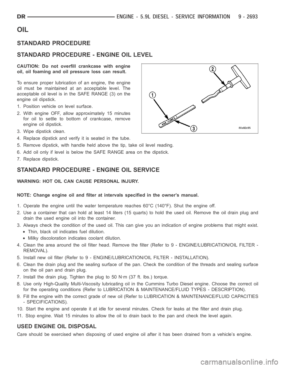
To ensure proper lubrication of an engine, the engine
oil must be maintained at an acceptable level. The
acceptable oil level is in the SAFE RANGE (3) on the
engine oil dipstick.
1. Position vehicle on level surface.
2. With engine OFF, allow approximately 15 minutes
for oil to settle to bottom of crankcase, remove
engine oil dipstick.
3. Wipe dipstick clean.
4. Replace dipstick and verify it is seated in the tube.
5. Remove dipstick, with handle held above the tip, take oil level reading.
6. Add oil only if level is below the SAFE RANGE area on the dipstick.
7. Replace dipstick.
STANDARD PROCEDURE - ENGINE OIL SERVICE
WARNING: HOT OIL CAN CAUSE PERSONAL INJURY.
NOTE: Change engine oil and filter at intervals specified in the owner’s manual.
1. Operate the engine until the water temperature reaches 60°C (140°F). Shut the engine off.
2. Use a container that can hold at least 14 liters (15 quarts) to hold the used oil. Remove the oil drain plug and
drain the used engine oil into the container.
3. Always check the condition of the used oil. This can give you an indication of engine problems that might exist.
Thin, black oil indicates fuel dilution.
Milky discoloration indicates coolant dilution.
4. Clean the area around the oil filter head. Remove the filter (Refer to 9 - ENGINE/LUBRICATION/OIL FILTER -
REMOVAL).
5. Install new oil filter (Refer to 9 - ENGINE/LUBRICATION/OIL FILTER - INSTA L L AT I O N ) .
6. Clean the drain plug and the sealing surface of the pan. Check the condition of the threads and sealing surface
on the oil pan and drain plug.
7. Install the drain plug. Tighten the plug to 50 Nꞏm (37 ft. lbs.) torque.
8. Use only High-Quality Multi-Viscosity lubricating oil in the Cummins Turbo Diesel engine. Choose the correct oil
for the operating conditions (Refer to LUBRICATION & MAINTENANCE/FLUID TYPES - DESCRIPTION).
9. Fill the engine with the correct grade of new oil (Refer to LUBRICATION & MAINTENANCE/FLUID CAPACITIES
- SPECIFICATIONS).
10. Start the engine and operate it at idle for several minutes. Check for leaks at the filter and drain plug.
11. Stop engine. Wait 15 minutes to allow the oil to drain back to the pan and check the level again.
USED ENGINE OIL DISPOSAL
Care should be exercised when disposing of used engine oil after it has beendrained from a vehicle’s engine.
Page 2011 of 5267
MANIFOLD - INTAKE
REMOVAL
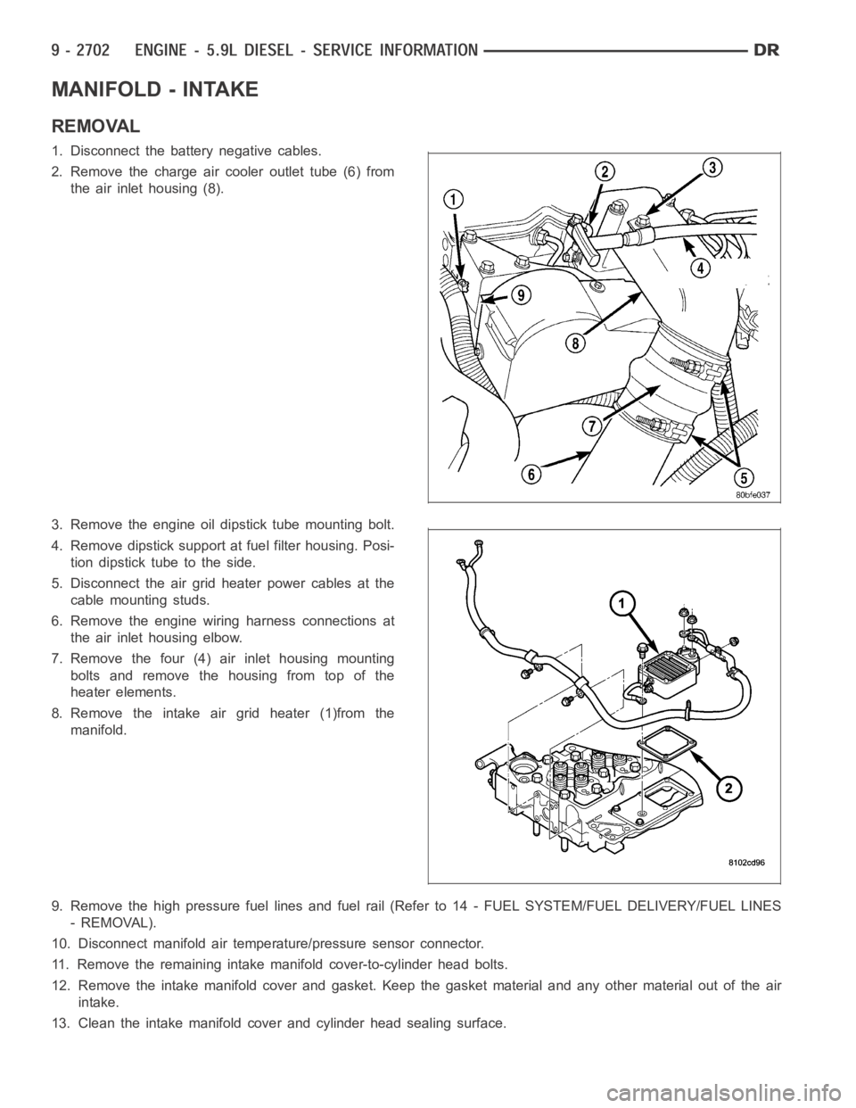
1. Disconnect the battery negative cables.
2. Remove the charge air cooler outlet tube (6) from
the air inlet housing (8).
3. Remove the engine oil dipstick tube mounting bolt.
4. Remove dipstick support at fuel filter housing. Posi-
tion dipstick tube to the side.
5. Disconnect the air grid heater power cables at the
cable mounting studs.
6. Remove the engine wiring harness connections at
the air inlet housing elbow.
7. Remove the four (4) air inlet housing mounting
bolts and remove the housing from top of the
heater elements.
8. Remove the intake air grid heater (1)from the
manifold.
9. Remove the high pressure fuel lines and fuel rail (Refer to 14 - FUEL SYSTEM/FUEL DELIVERY/FUEL LINES
- REMOVAL).
10. Disconnect manifold air temperature/pressure sensor connector.
11. Remove the remaining intake manifold cover-to-cylinder head bolts.
12. Remove the intake manifold cover and gasket. Keep the gasket material and any other material out of the air
intake.
13. Clean the intake manifold cover and cylinder head sealing surface.