2006 DODGE RAM SRT-10 oil temperature
[x] Cancel search: oil temperaturePage 1536 of 5267
HEAD-CYLINDER-RIGHT
DIAGNOSIS AND TESTING - HYDRAULIC LASH ADJUSTER
A tappet-like noise may be produced from several items. Check the followingitems.
1. Engine oil level too high or too low. This may cause aerated oil to enter the adjusters and cause them to be
spongy.
2. Insufficient running time after rebuilding cylinder head. Low speed runningupto1hourmayberequired.
3. Turn engine off and let set for a few minutes before restarting. Repeat this several times after engine has
reached normal operating temperature.
4. Low oil pressure.
5. The oil restrictor in cylinder head gasket or the oil passage to the cylinder head is plugged with debris.
6. Airingestedintooilduetobrokenorcrackedoilpumppickup.
7. Worn valve guides.
8. Rocker arm ears contacting valve spring retainer.
9. Rocker arm loose, adjuster stuck or at maximum extension and still leaves lash in the system.
10. Oil leak or excessive cam bore wear in cylinder head.
11. Faulty lash adjuster.
a. Check lash adjusters for sponginess while installed in cylinder head and cam on camshaft at base circle.
Depress part of rocker arm over adjuster. Normal adjusters should feel firm when pressed quickly. When pressed
very slowly, lash adjusters should collapse.
b. Remove suspected lash adjusters, and replace.
c. Before installation, make sure adjusters are full of oil. This can be verified by little plunger travel when lash
adjuster is depressed quickly.
REMOVAL
REMOVAL RIGHT CYLINDER HEAD
1. Disconnect battery negative cable.
2. Raise the vehicle on a hoist.
3. Disconnect the exhaust pipe at the right side
exhaust manifold.
4. Drain the engine coolant (Refer to 7 - COOLING -
STANDARD PROCEDURE).
5. Lower the vehicle.
6. Remove the intake manifold (Refer to 9 - ENGINE/
MANIFOLDS/INTAKE MANIFOLD - REMOVAL).
7. Remove the cylinder head cover (Refer to 9 -
ENGINE/CYLINDER HEAD - REMOVAL).
8. Remove the fan shroud (Refer to 7 - COOLING/
ENGINE/RADIATOR FAN - REMOVAL).
9. Remove oil fill housing from cylinder head.
10. Remove accessory drive belt (Refer to 7 - COOL-
ING/ACCESSORY DRIVE/DRIVE BELTS -
REMOVAL).
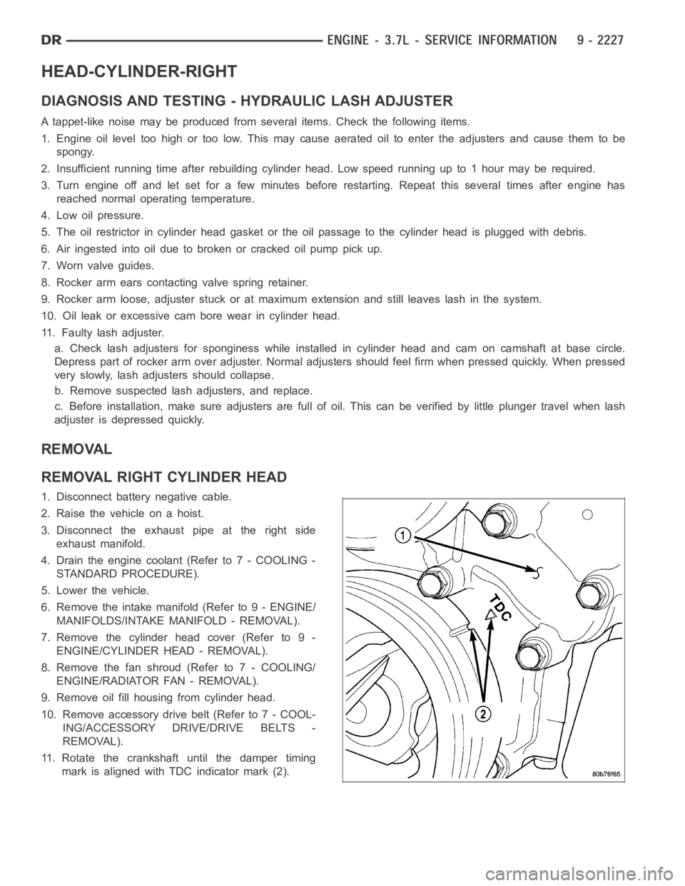
11. Rotate the crankshaft until the damper timing
mark is aligned with TDC indicator mark (2).
Page 1598 of 5267
OIL
STANDARD PROCEDURE - ENGINE OIL SERVICE
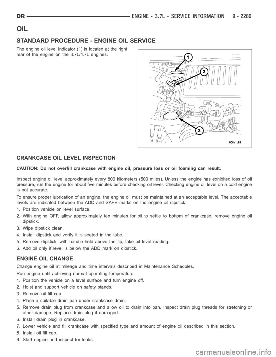
The engine oil level indicator (1) is located at the right
rear of the engine on the 3.7L/4.7L engines.
CRANKCASE OIL LEVEL INSPECTION
CAUTION: Do not overfill crankcase with engine oil, pressure loss or oil foaming can result.
Inspect engine oil level approximately every 800 kilometers (500 miles).Unless the engine has exhibited loss of oil
pressure, run the engine for about five minutes before checking oil level.Checking engine oil level on a cold engine
is not accurate.
To ensure proper lubrication of an engine, the engine oil must be maintained at an acceptable level. The acceptable
levels are indicated between the ADD and SAFE marks on the engine oil dipstick.
1. Position vehicle on level surface.
2. With engine OFF, allow approximately ten minutes for oil to settle to bottom of crankcase, remove engine oil
dipstick.
3. Wipe dipstick clean.
4. Install dipstick and verify it is seated in the tube.
5. Remove dipstick, with handle held above the tip, take oil level reading.
6. Add oil only if level is below the ADD mark on dipstick.
ENGINE OIL CHANGE
Change engine oil at mileage and time intervals described in Maintenance Schedules.
Run engine until achieving normal operating temperature.
1. Position the vehicle on a level surface and turn engine off.
2. Hoist and support vehicle on safety stands.
3. Remove oil fill cap.
4. Place a suitable drain pan under crankcase drain.
5. Remove drain plug from crankcase and allow oil to drain into pan. Inspectdrain plug threads for stretching or
other damage. Replace drain plug if damaged.
6. Install drain plug in crankcase.
7. Lower vehicle and fill crankcase with specified type and amount of engine oil described in this section.
8. Install oil fill cap.
9. Start engine and inspect for leaks.
Page 1601 of 5267
5. Disconnect vapor purge hose, brake booster hose, speed control servo hose, positive crankcase ventilation
(PCV) hose.
6. Disconnect generator electrical connections.
7. Disconnect air conditioning compressor electrical connections.
8. Disconnect left and right radio suppressor straps.
9. Disconnect and remove ignition coil towers.
10. Remove top oil dipstick tube retaining bolt and ground strap.
11. Bleed fuel system (Refer to 14 - FUEL SYSTEM/FUEL DELIVERY - STANDARD PROCEDURE).
12. Remove fuel rail.
13. Remove throttle body assembly and mounting bracket.
14. Drain cooling system below coolant temperature level (Refer to 7 - COOLING - STANDARD PROCEDURE).
15. Remove the heater hoses from the engine front cover and the heater core.
16. Unclip and remove heater hoses and tubes from intake manifold.
17. Remove coolant temperature sensor (Refer to 7 - COOLING/ENGINE/ENGINE COOLANT TEMP SENSOR -
REMOVAL).
18. Remove intake manifold retaining fasteners in reverse order of tightening sequence.
19. Remove intake manifold.
INSTALLATION
1. Install intake manifold gaskets.
2. Install intake manifold.
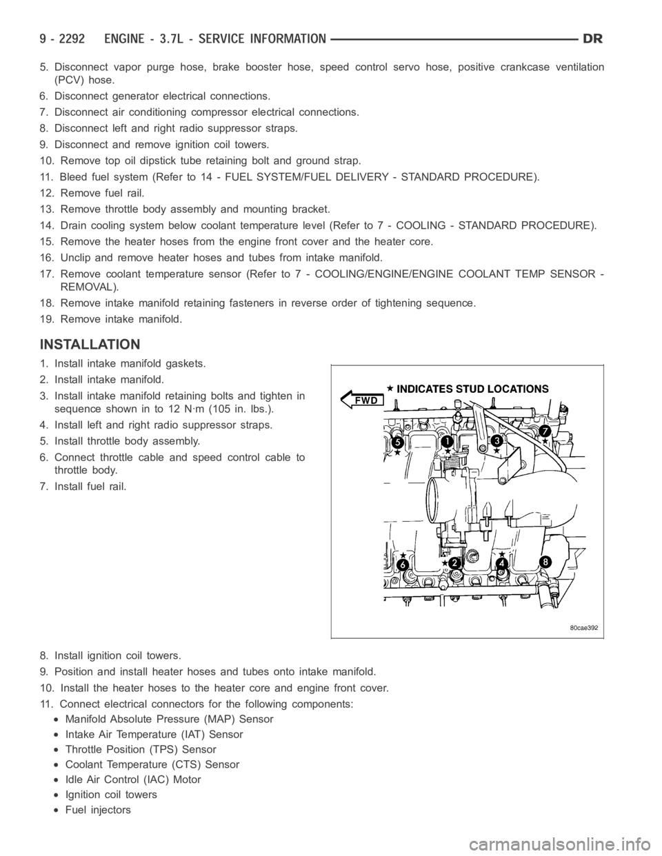
3. Install intake manifold retaining bolts and tighten in
sequence shown in to 12 Nꞏm (105 in. lbs.).
4. Install left and right radio suppressor straps.
5. Install throttle body assembly.
6. Connect throttle cable and speed control cable to
throttle body.
7. Install fuel rail.
8. Install ignition coil towers.
9. Position and install heater hoses and tubes onto intake manifold.
10. Install the heater hoses to the heater core and engine front cover.
11. Connect electrical connectors for the following components:
Manifold Absolute Pressure (MAP) Sensor
Intake Air Temperature (IAT) Sensor
Throttle Position (TPS) Sensor
Coolant Temperature (CTS) Sensor
Idle Air Control (IAC) Motor
Ignition coil towers
Fuel injectors
Page 1628 of 5267
Ensurethebatteryiscompletelychargedandtheenginestartermotorisingood operating condition. Otherwise the
indicated compression pressures may not be valid for diagnosis purposes.
1. Clean the spark plug recesses with compressed air.
2. Remove the spark plugs.
3. Disable the fuel system (Refer to 14 - FUEL SYSTEM/FUEL DELIVERY - DESCRIPTION).
4. Remove the ASD relay (Refer to 8 - ELECTRICAL/IGNITION CONTROL/AUTO SHUTDOWNRELAY-
REMOVAL).
5. Insert a compression pressure gauge and rotate the engine with the engine starter motor for three revolutions.
6. Record the compression pressure on the 3rd revolution. Continue the test for the remaining cylinders.
7. (Refer to 9 - ENGINE - SPECIFICATIONS) for the correct engine compression pressures.
DIAGNOSIS AND TESTING - CYLINDERCOMBUSTION PRESSURE LEAKAGE
The combustion pressure leakage test provides an accurate means for determining engine condition.
Combustion pressure leakage testing will detect:
Exhaust and intake valve leaks (improper seating).
Leaks between adjacent cylinders or into water jacket.
Any causes for combustion/compression pressure loss.
1. Check the coolant level and fill as required. DO NOT install the radiatorcap.
2. Start and operate the engine until it attains normal operating temperature, then turn the engine OFF.
3. Remove the spark plugs.
4. Remove the oil filler cap.
5. Remove the air cleaner hose.
6. Calibrate the tester according to the manufacturer’s instructions. The shop air source for testing should maintain
483 kPa (70 psi) minimum, 1,379 kPa (200 psi) maximum and 552 kPa (80 psi) recommended.
7. Perform the test procedures on each cylinder according to the tester manufacturer’s instructions. Set piston of
cylinder to be tested at TDC compression,While testing, listen for pressurized air escaping through the throttle
body, tailpipe and oil filler cap opening. Check for bubbles in the radiator coolant.
All gauge pressure indications should be equal, with no more than 25% leakage.
FOR EXAMPLE:At 552 kPa (80 psi) input pressure, a minimum of 414 kPa (60 psi) should be maintained in the
cylinder.
Refer to CYLINDER COMBUSTION PRESSURE LEAKAGE DIAGNOSIS CHART .
CYLINDER COMBUSTION PRESSURE LEAKAGE DIAGNOSIS CHART
CONDITION POSSIBLE CAUSE CORRECTION
AIR ESCAPES THROUGH
THROTTLE BODYIntake valve bent, burnt, or not
seated properlyInspect valve and valve seat.
Reface or replace, as necessary.
Inspect valve springs. Replace as
necessary.
AIR ESCAPES THROUGH
TAILPIPEExhaust valve bent, burnt, or not
seated properlyInspect valve and valve seat.
Reface or replace, as necessary.
Inspect valve springs. Replace as
necessary.
AIR ESCAPES THROUGH
RADIATORHead gasket leaking or cracked
cylinder head or blockRemove cylinder head and inspect.
Replace defective part
MORE THAN 50% LEAKAGE
FROM ADJACENT CYLINDERSHead gasket leaking or crack in
cylinder head or block between
adjacent cylindersRemove cylinder head and inspect.
Replace gasket, head, or block as
necessary
Page 1630 of 5267
able in three ounce tubes and has a shelf life of one year. After one year thismaterial will not properly cure. Always
inspect the package for the expiration date before use.
MOPAR
GASKET MAKER
Mopar
Gasket Maker is an anaerobic type gasket material. The material cures in the absence of air when
squeezed between two metallic surfaces. It will not cure if left in the uncovered tube. The anaerobic material is for
use between two machined surfaces. Do not use on flexible metal flanges.
MOPAR
GASKET SEALANT
Mopar
Gasket Sealant is a slow drying, permanently soft sealer. This material isrecommended for sealing
threaded fittings and gaskets against leakage of oil and coolant. Can be used on threaded and machined parts
under all temperatures. This material is used on engines with multi-layersteel (MLS) cylinder head gaskets. This
material also will prevent corrosion. Mopar
Gasket Sealant is available in a 13 oz. aerosol can or 4oz./16 oz. can
w/applicator.
FORM-IN-PLACE GASKET AND SEALER APPLICATION
Assembling parts using a form-in-place gasket requires care but it’s easier than using precut gaskets.
Mopar
Gasket Maker material should be applied sparingly 1 mm (0.040 in.) diameter or less of sealant to one
gasket surface. Be certain the material surrounds each mounting hole. Excess material can easily be wiped off.
Components should be torqued in place within 15 minutes. The use of a locating dowel is recommended during
assembly to prevent smearing material off the location.
Mopar
Engine RTV GEN II or ATF RTV gasket material should be applied in a continuous bead approximately 3
mm (0.120 in.) in diameter. All mounting holes must be circled. For corner sealing, a 3.17 or 6.35 mm (1/8 or 1/4 in.)
drop is placed in the center of the gasket contact area. Uncured sealant maybe removed with a shop towel. Com-
ponents should be torqued in place while the sealant is still wet to the touch (within 10 minutes). The usage of a
locating dowel is recommended during assembly to prevent smearing material off the location.
Mopar
Gasket Sealant in an aerosol can should be applied using a thin, even coat sprayed completely over both
surfaces to be joined, and both sides of a gasket. Then proceed with assembly. Material in a can w/applicator can
be brushed on evenly over the sealing surfaces. Material in an aerosol can shouldbeusedonengineswithmulti-
layer steel gaskets.
REMOVAL
NOTE:Thisprocedureappliestoboththe4X2and4X4vehicles,stepsthatapply to the 4X4 vehicle only,
are identified.
1. Release fuel rail pressure (Refer to 14 - FUEL SYSTEM/FUEL DELIVERY - STANDARD PROCEDURE) then
disconnect the fuel supply quick connect fitting at the fuel rail (Refer to14 - FUEL SYSTEM/FUEL DELIVERY/
QUICK CONNECT FITTING - STANDARD PROCEDURE).
2. Disconnect the battery negative and positive cables.
3. Raise vehicle on hoist.
4. Remove exhaust crossover pipe from exhaust manifolds.
5.4X4 vehiclesDisconnect axle vent tube from left side engine mount.
6. Remove the through bolt retaining nut and bolt from both the left and right side engine mounts.
7.4X4 vehiclesRemove locknut from left and right side engine mount brackets.
8. Disconnect two ground straps from the lower left hand side and one groundstrap from the lower right hand side
of the engine.
Page 1634 of 5267
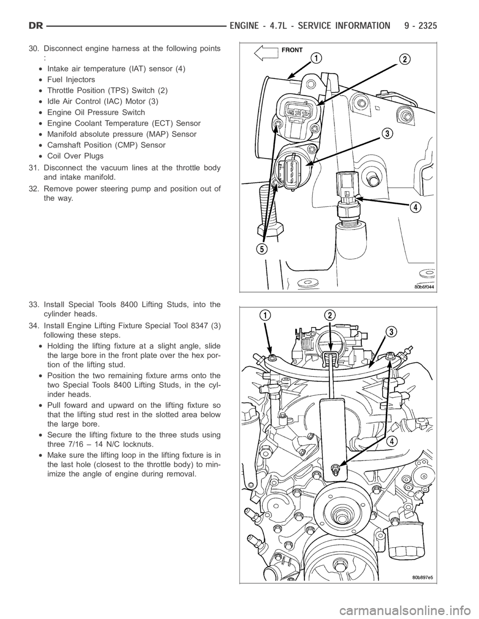
30. Disconnect engine harness at the following points
:
Intake air temperature (IAT) sensor (4)
Fuel Injectors
Throttle Position (TPS) Switch (2)
Idle Air Control (IAC) Motor (3)
Engine Oil Pressure Switch
Engine Coolant Temperature (ECT) Sensor
Manifold absolute pressure (MAP) Sensor
Camshaft Position (CMP) Sensor
Coil Over Plugs
31. Disconnect the vacuum lines at the throttle body
and intake manifold.
32. Remove power steering pump and position out of
the way.
33. Install Special Tools 8400 Lifting Studs, into the
cylinder heads.
34. Install Engine Lifting Fixture Special Tool 8347 (3)
following these steps.
Holding the lifting fixture at a slight angle, slide
the large bore in the front plate over the hex por-
tion of the lifting stud.
Position the two remaining fixture arms onto the
two Special Tools 8400 Lifting Studs, in the cyl-
inder heads.
Pull foward and upward on the lifting fixture so
that the lifting stud rest in the slotted area below
the large bore.
Secure the lifting fixture to the three studs using
three 7/16 – 14 N/C locknuts.
Make sure the lifting loop in the lifting fixture is in
the last hole (closest to the throttle body) to min-
imize the angle of engine during removal.
Page 1637 of 5267
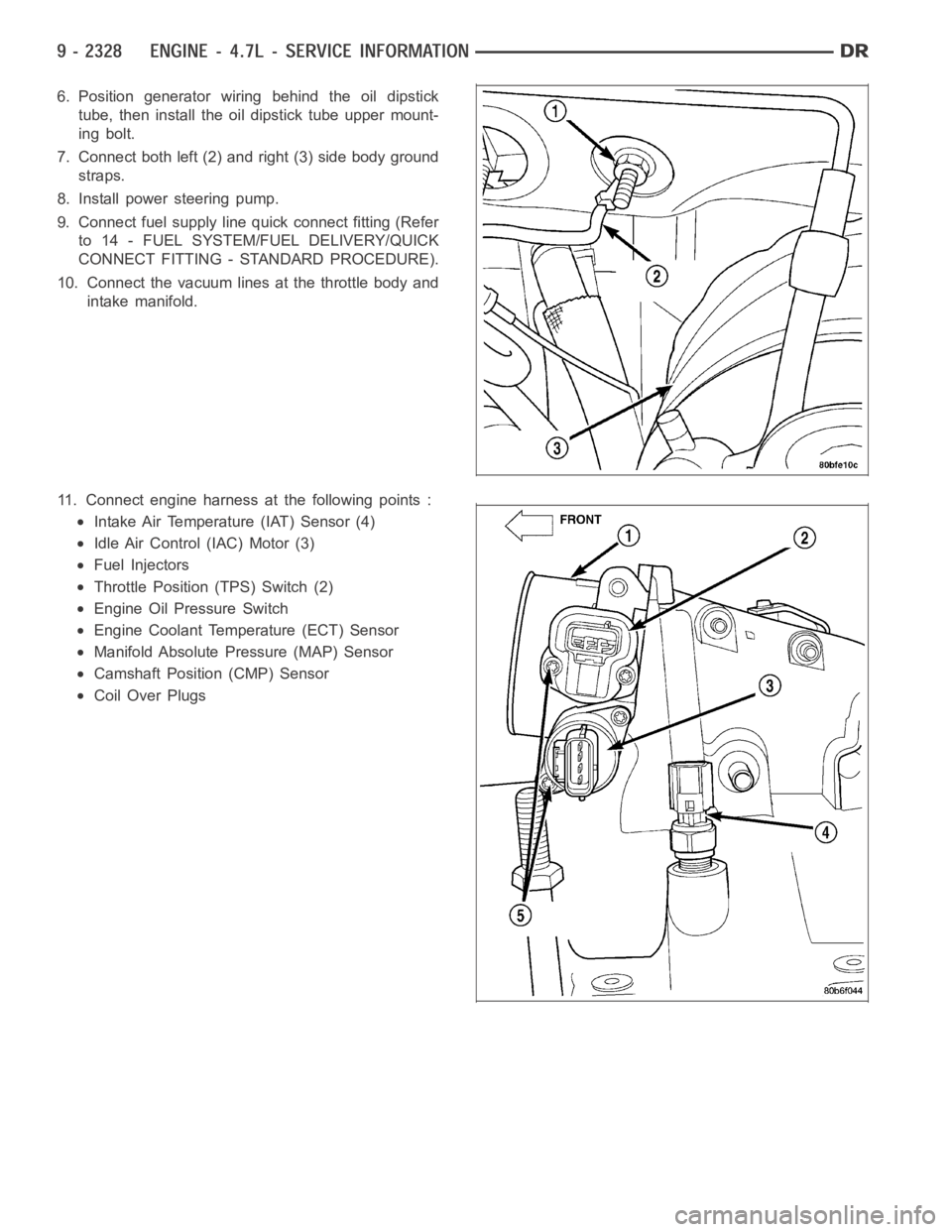
6. Position generator wiring behind the oil dipstick
tube, then install the oil dipstick tube upper mount-
ing bolt.
7. Connect both left (2) and right (3) side body ground
straps.
8. Install power steering pump.
9. Connect fuel supply line quick connect fitting (Refer
to 14 - FUEL SYSTEM/FUEL DELIVERY/QUICK
CONNECT FITTING - STANDARD PROCEDURE).
10. Connect the vacuum lines at the throttle body and
intake manifold.
11. Connect engine harness at the following points :
Intake Air Temperature (IAT) Sensor (4)
Idle Air Control (IAC) Motor (3)
Fuel Injectors
Throttle Position (TPS) Switch (2)
Engine Oil Pressure Switch
Engine Coolant Temperature (ECT) Sensor
Manifold Absolute Pressure (MAP) Sensor
Camshaft Position (CMP) Sensor
Coil Over Plugs
Page 1683 of 5267
ROCKER ARM - VALVE
DESCRIPTION
The rocker arms are steel stampings with an integral roller bearing. The rocker arms incorporate an 0.5 mm (0.019
inch) oil hole in the ball socket forroller and camshaft lubrication.
DIAGNOSIS AND TESTING - HYDRAULIC LASH ADJUSTER
A tappet-like noise may be produced from several items. Check the followingitems.
1. Engine oil level too high or too low. This may cause aerated oil to enter the adjusters and cause them to be
spongy.
2. Insufficient running time after rebuilding cylinder head. Low speed runningupto1hourmayberequired.
3. Turn engine off and let set for a few minutes before restarting. Repeat this several times after engine has
reached normal operating temperature.
4. Low oil pressure.
5. The oil restrictor in cylinder head gasket or the oil passage to the cylinder head is plugged with debris.
6. Airingestedintooilduetobrokenorcrackedoilpumppickup.
7. Worn valve guides.
8. Rocker arm ears contacting valve spring retainer.
9. Rocker arm loose, adjuster stuck or at maximum extension and still leaves lash in the system.
10. Oil leak or excessive cam bore wear in cylinder head.
11. Faulty lash adjuster.
a. Check lash adjusters for sponginess while installed in cylinder head and cam on camshaft at base circle.
Depress part of rocker arm over adjuster. Normal adjusters should feel very firm. Spongy adjusters can be bot-
tomed out easily.
b. Remove suspected lash adjusters, and replace.
c. Before installation, make sure adjusters are at least partially full ofoil. This can be verified by little or no
plunger travel when lash adjuster is depressed.
REMOVAL
NOTE: Disconnect the battery negative cable to
prevent accidental starter engagement.
1. Remove the cylinder head cover (Refer to 9 -
ENGINE/CYLINDER HEAD/CYLINDER HEAD
COVER(S) - REMOVAL).
2. For rocker arm removal on cylinders 3 and 5
Rotate the crankshaft until cylinder #1 is at TDC
exhaust stroke.
3. For rocker arm removal on cylinders 2 and 8
Rotate the crankshaft until cylinder #1 is at TDC
compression stroke.
4. For rocker arm removal on cylinders 4 and 6
Rotate the crankshaft until cylinder #3 is at TDC
compression stroke.
5. For rocker arm removal on cylinders 1 and 7
Rotate the crankshaft until cylinder #2 is at TDC
compression stroke.
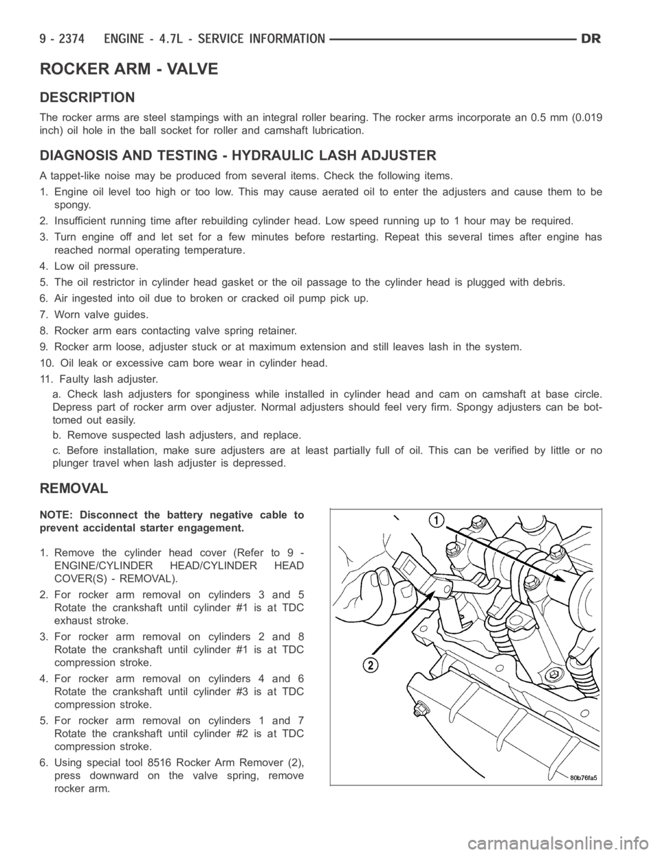
6. Using special tool 8516 Rocker Arm Remover (2),
press downward on the valve spring, remove
rocker arm.