Page 2080 of 5267

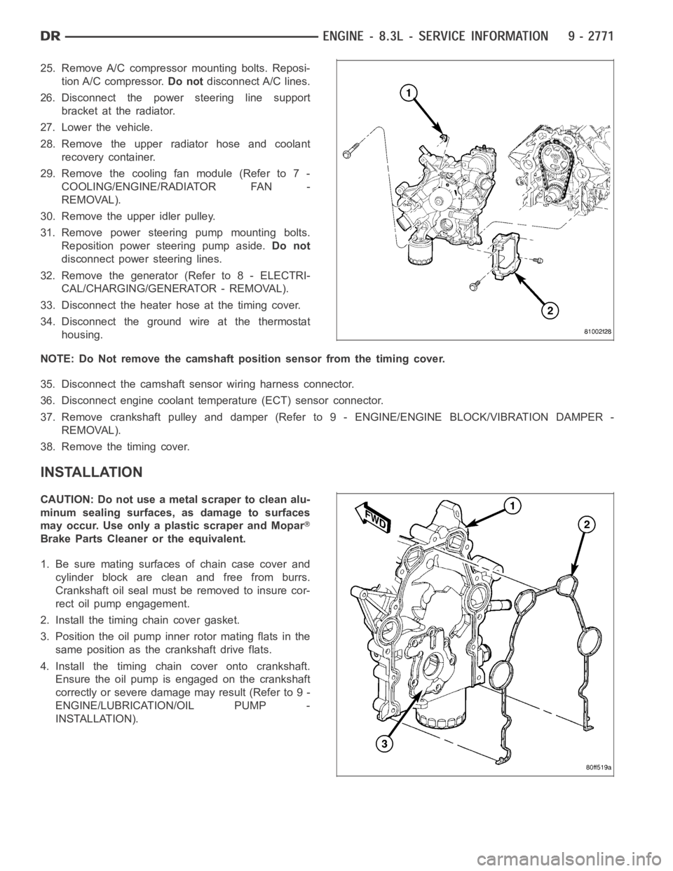
25. Remove A/C compressor mounting bolts. Reposi-
tion A/C compressor.Do notdisconnect A/C lines.
26. Disconnect the power steering line support
bracket at the radiator.
27. Lower the vehicle.
28. Remove the upper radiator hose and coolant
recovery container.
29. Remove the cooling fan module (Refer to 7 -
COOLING/ENGINE/RADIATOR FAN -
REMOVAL).
30. Remove the upper idler pulley.
31. Remove power steering pump mounting bolts.
Reposition power steering pump aside.Do not
disconnect power steering lines.
32. Remove the generator (Refer to 8 - ELECTRI-
CAL/CHARGING/GENERATOR - REMOVAL).
33. Disconnect the heater hose at the timing cover.
34. Disconnect the ground wire at the thermostat
housing.
NOTE: Do Not remove the camshaft position sensor from the timing cover.
35. Disconnect the camshaft sensor wiring harness connector.
36. Disconnect engine coolant temperature (ECT) sensor connector.
37. Remove crankshaft pulley and damper (Refer to 9 - ENGINE/ENGINE BLOCK/VIBRATION DAMPER -
REMOVAL).
38. Remove the timing cover.
INSTALLATION
CAUTION: Do not use a metal scraper to clean alu-
minum sealing surfaces, as damage to surfaces
may occur. Use only a plastic scraper and Mopar
Brake Parts Cleaner or the equivalent.
1. Be sure mating surfaces of chain case cover and
cylinder block are clean and free from burrs.
Crankshaft oil seal must be removed to insure cor-
rect oil pump engagement.
2. Install the timing chain cover gasket.
3. Position the oil pump inner rotor mating flats in the
same position as the crankshaft drive flats.
4. Install the timing chain cover onto crankshaft.
Ensure the oil pump is engaged on the crankshaft
correctly or severe damage may result (Refer to 9 -
ENGINE/LUBRICATION/OIL PUMP -
INSTALLATION).
Page 2081 of 5267

5. Hand start bolts No.1 and No.2.
6. Loosely install A/C compressor mounting bracket.
7. Hand start remaining timing chain cover bolts.
8. Torque timing chain cover bolts in the sequence
showninto23Nꞏm(200in.lbs.).
9. Torque A/C compressor mounting bracket bolts to
23 Nꞏm (200 in. lbs.).
10. Install crankshaft oil seal (Refer to 9 - ENGINE/
ENGINE BLOCK/CRANKSHAFT OIL SEAL -
FRONT - INSTALLATION).
11. Raise vehicle on hoist.
12. Install oil pump pick up tube using anewo-ring.
Torque 1/4–20 bolt to 11 Nꞏm (95 in. lbs.). Torque
5/16–18 nuts to 23 Nꞏm (200 in. lbs.).
13. Support the engine with a jack stand.
14. Install oil pan and drain plug (Refer to 9 -
ENGINE/LUBRICATION/OIL PAN - INSTALLA-
TION).
15. Remove the jackstand.
16. Tighten the engine mount to frame nuts to 102
Nꞏm (75 ft.lbs.).
17. Connect the oil cooler coolant hose to the timing
cover.
18. Connect the oil cooler line (Refer to 9 - ENGINE/
LUBRICATION/OIL COOLER & LINES - STAN-
DARD PROCEDURE).
19. Install the lower radiator hose.
20. Install the flywheel inspection cover.
21. Install the front frame cross member (Refer to 13
- FRAME & BUMPERS/FRAME/FRONT CROSS-
MEMBER - INSTALLATION).
22. Lower vehicle.
23. Position the compressor and install A/C compressor mounting bolts. Torque bolts to 23 Nꞏm (200 in. lbs.).
24. Connect heater hose at timing cover.
25. Install crankshaft damper and pulley (Refer to 9 - ENGINE/ENGINE BLOCK/VIBRATION DAMPER - INSTAL-
LATION).
26. Install generator. Connect electrical connectors.
27. Install the idler pulley.
28. Connect the camshaft position sensor wiring harness connector.
29. Connect engine coolant temperature (ECT) sensor wiring harness connector.
30. Install power steering pump mounting bolts.
31. Install accessory drive belt (Refer to 7 - COOLING/ACCESSORY DRIVE/DRIVE BELTS - INSTALLATION).
32. Install the radiator fan assembly (Refer to 7 - COOLING/ENGINE/RADIATOR FAN - INSTALLATION).
Page 2088 of 5267

OIL
STANDARD PROCEDURE
CHECKING ENGINE OIL LEVEL
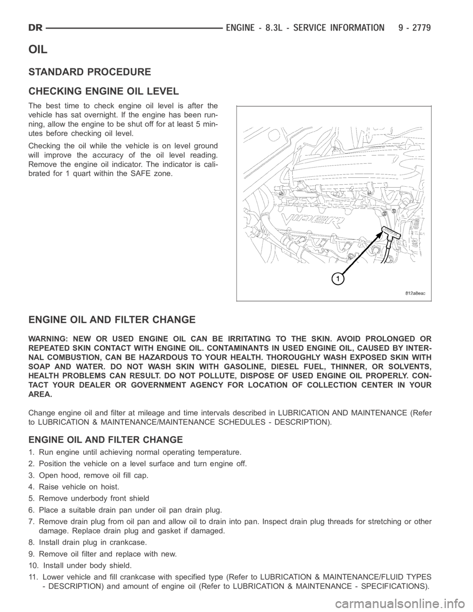
The best time to check engine oil level is after the
vehicle has sat overnight. If the engine has been run-
ning, allow the engine to be shut off for at least 5 min-
utes before checking oil level.
Checking the oil while the vehicle is on level ground
will improve the accuracy of the oil level reading.
Remove the engine oil indicator. The indicator is cali-
brated for 1 quart within the SAFE zone.
ENGINE OIL AND FILTER CHANGE
WARNING: NEW OR USED ENGINE OIL CAN BE IRRITATING TO THE SKIN. AVOID PROLONGED OR
REPEATED SKIN CONTACT WITH ENGINE OIL. CONTAMINANTS IN USED ENGINE OIL, CAUSED BY INTER-
NAL COMBUSTION, CAN BE HAZARDOUS TO YOUR HEALTH. THOROUGHLY WASH EXPOSED SKIN WITH
SOAP AND WATER. DO NOT WASH SKIN WITH GASOLINE, DIESEL FUEL, THINNER, OR SOLVENTS,
HEALTH PROBLEMS CAN RESULT. DO NOT POLLUTE, DISPOSE OF USED ENGINE OIL PROPERLY. CON-
TACT YOUR DEALER OR GOVERNMENT AGENCY FOR LOCATION OF COLLECTION CENTER INYOUR
AREA.
Change engine oil and filter at mileage and time intervals described in LUBRICATION AND MAINTENANCE (Refer
to LUBRICATION & MAINTENANCE/MAINTENANCE SCHEDULES - DESCRIPTION).
ENGINE OIL AND FILTER CHANGE
1. Run engine until achieving normal operating temperature.
2. Position the vehicle on a level surface and turn engine off.
3. Open hood, remove oil fill cap.
4. Raise vehicle on hoist.
5. Remove underbody front shield
6. Place a suitable drain pan under oil pan drain plug.
7. Remove drain plug from oil pan and allow oil to drain into pan. Inspect drain plug threads for stretching or other
damage. Replace drain plug and gasket if damaged.
8. Install drain plug in crankcase.
9. Remove oil filter and replace with new.
10. Install under body shield.
11. Lower vehicle and fill crankcase with specified type (Refer to LUBRICATION & MAINTENANCE/FLUID TYPES
- DESCRIPTION) and amount of engine oil (Refer to LUBRICATION & MAINTENANCE - SPECIFICATIONS).
Page 2103 of 5267
SENSOR-OIL TEMPERATURE
REMOVAL
1. Disconnect oil temperature sensor electrical con-
nector.
2. Remove oil temperature sensor (5).
INSTALLATION
1. Apply thread sealer to oil temperature sensor
threads.
2. Install oil temperature sensor (5).
3. Connect electrical connector.
Page 2107 of 5267
INSTALLATION
1. Lubricate tappets.
2. Install tappets in their original positions with oil
holes (1) facing up.
CAUTION: The “handle” on the tappet aligning
yoke must be installed in the outboard position;
i.e. toward the cylinders.
3. With roller tappets in proper position, install align-
ing yoke assemblies. Apply Mopar
Lock & Seal
Adhesive (Medium Strength Threadlocker) to the
screwsandtightento11Nꞏm(95in.lbs.).
4. Install cylinder heads (Refer to 9 - ENGINE/CYLIN-
DER HEAD - INSTALLATION).
5. Start and operate engine. Warm up to normal oper-
ating temperature.
CAUTION: To prevent damage to valve mecha-
nism, engine must not be run above fast idle until
all hydraulic tappets have filled with oil and have
become quiet.
Page 2111 of 5267

ROD-PISTON & CONNECTING
DESCRIPTION
The pistons are made of cast aluminum with an added anodized coating on bothsides of the skirt and the top
piston ring groove for reduced wear and it’s low friction properties. Three piston rings are used; two compression
and one three-piece oil control ring. The piston pin (press-fit into the rods) joins the piston to a forged steel, frac-
tured cap, designed connecting rod, with a custom twelve point nine millimeter threaded bolt. The piston and con-
necting rod is serviced as an assembly and is not interchangeable with previous model years.
STANDARD PROCEDURE
PISTON FITTING
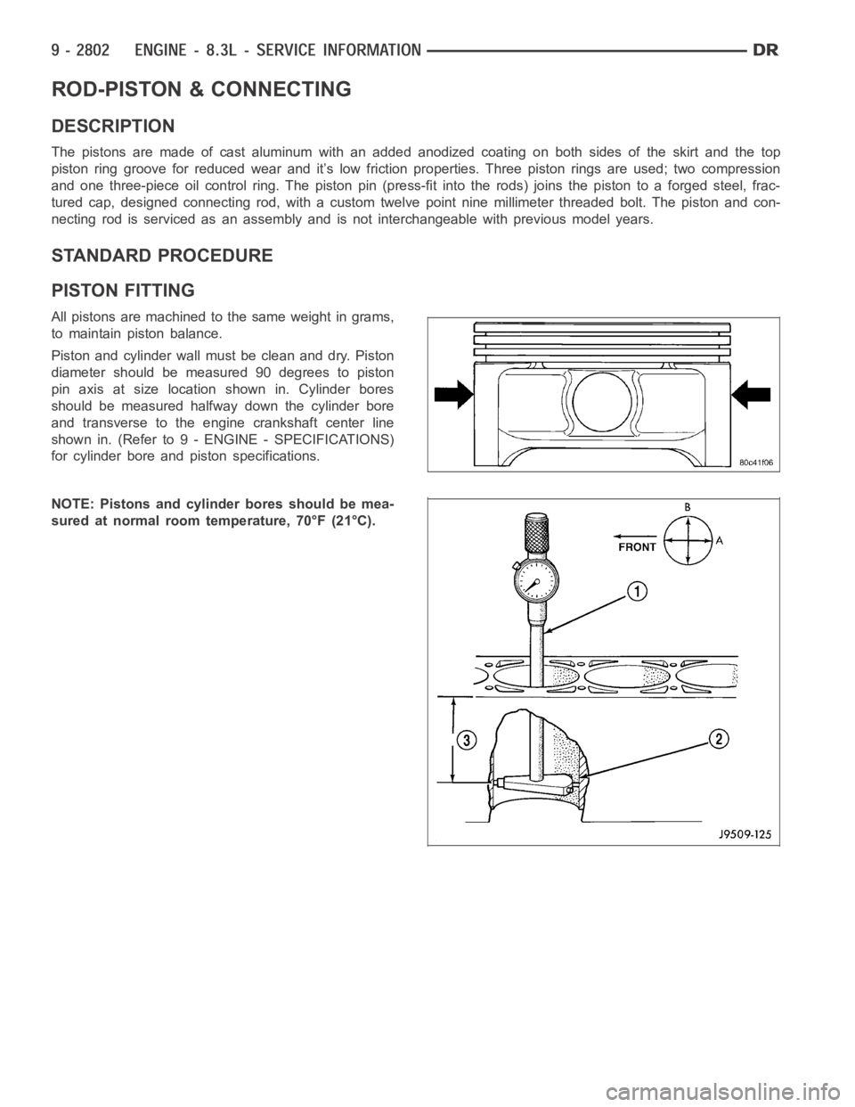
All pistons are machined to the same weight in grams,
to maintain piston balance.
Piston and cylinder wall must be clean and dry. Piston
diameter should be measured 90 degrees to piston
pin axis at size location shown in. Cylinder bores
should be measured halfway down the cylinder bore
and transverse to the engine crankshaft center line
shown in. (Refer to 9 - ENGINE - SPECIFICATIONS)
for cylinder bore and piston specifications.
NOTE: Pistons and cylinder bores should be mea-
sured at normal room temperature, 70°F (21°C).
Page 2163 of 5267

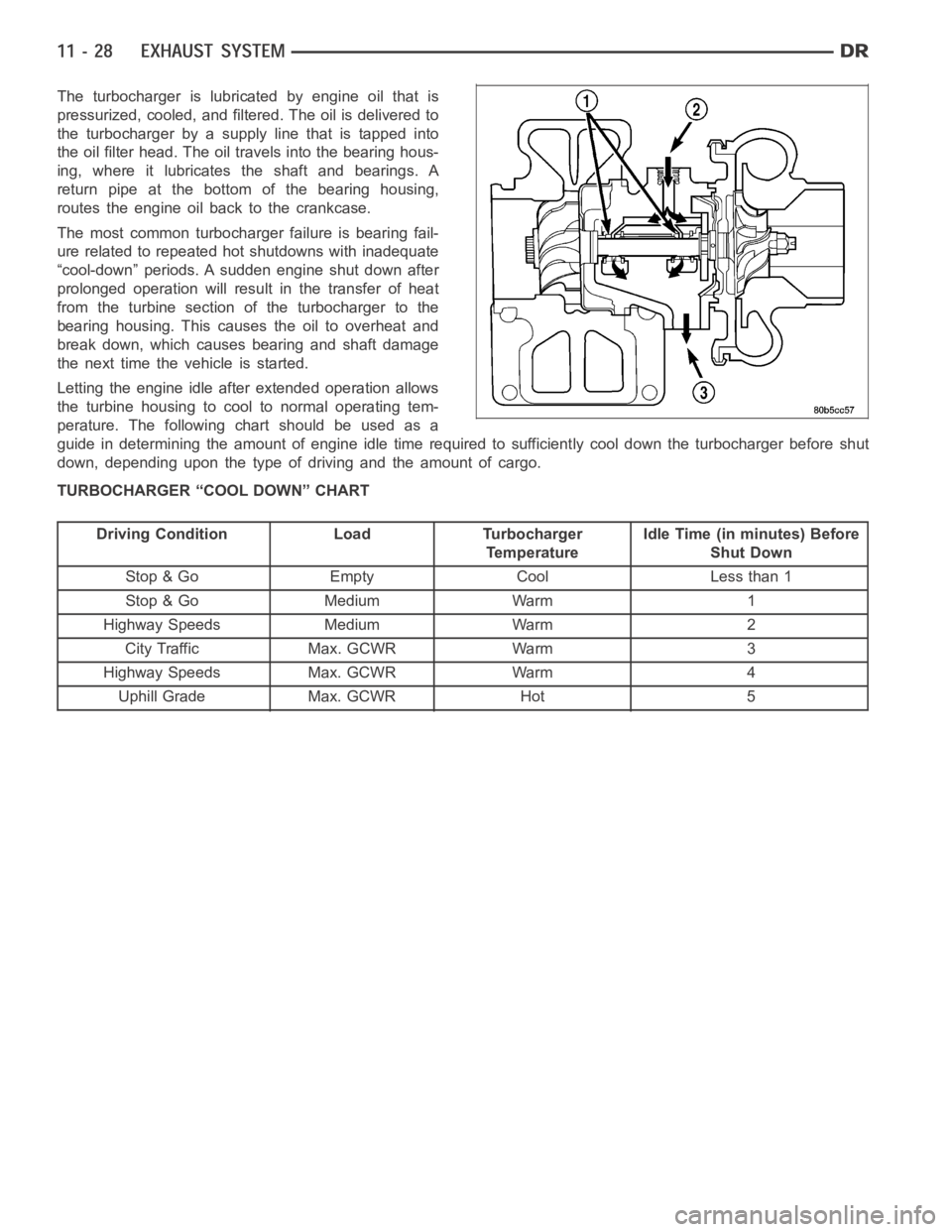
The turbocharger is lubricated by engine oil that is
pressurized, cooled, and filtered. The oil is delivered to
the turbocharger by a supply line that is tapped into
the oil filter head. The oil travels into the bearing hous-
ing, where it lubricates the shaft and bearings. A
return pipe at the bottom of the bearing housing,
routes the engine oil back to the crankcase.
The most common turbocharger failure is bearing fail-
ure related to repeated hot shutdowns with inadequate
“cool-down” periods. A sudden engine shut down after
prolonged operation will result in the transfer of heat
from the turbine section of the turbocharger to the
bearing housing. This causes the oil to overheat and
break down, which causes bearing and shaft damage
thenexttimethevehicleisstarted.
Letting the engine idle after extended operation allows
the turbine housing to cool to normal operating tem-
perature. The following chart should be used as a
guide in determining the amount of engine idle time required to sufficiently cool down the turbocharger before shut
down, depending upon the type of driving and the amount of cargo.
TURBOCHARGER “COOL DOWN” CHART
Driving Condition Load Turbocharger
TemperatureIdle Time (in minutes) Before
Shut Down
Stop & Go Empty Cool Less than 1
Stop & Go Medium Warm 1
Highway Speeds Medium Warm 2
City Traffic Max. GCWR Warm 3
Highway Speeds Max. GCWR Warm 4
Uphill Grade Max. GCWR Hot 5
Page 2297 of 5267

12. Remove the fuel injector from the fuel rail.
INSTALLATION
3.7/ 4.7/ 5.7L
1. Install fuel injector(s) into fuel rail assembly and install retainingclip(s).
2. If same injector(s) is being reinstalled, install new O-ring(s).
3. Apply a small amount of clean engine oil to each injector O-ring. This will aid in installation.
4. Install fuel rail. (Refer to 14 - FUEL SYSTEM/FUEL DELIVERY/FUEL RAIL - INSTALLATION)
5. Start engine and check for fuel leaks.
8.3L - SRT-10
1. Install the fuel injectors to the fuel rail.
2. Install fuel rail under throttle body.
3. Apply a light coating of clean engine oiltotheO-ringonthenozzleendofeach injector.
4. Insert fuel injector nozzles into openings in intake manifold. Seat theinjectors in place. Tighten fuel rail bolts to
12 Nꞏm (105 in. lbs.).
5. Attach electrical connectors to fuel injectors.
6. Connect the electrical connector to the MAP sensor and Coolant Temperature sensor.
7. Connect the electrical connector to the TPS and Idle Air Control.
8. Install the wiring harness to the wiring clips under the throttle body.
9. Connect fuel supply tube to fuel rail. Refer to Quick Connect Fittings inthe Fuel Delivery section
10. Install the negative battery cable and install the battery cover.
11. Install the air cleaner assembly, refer to the Engine/Air Intake System/Air Cleaner Housing for more information.
12. Use the DRBIII
scan tool ASD Fuel System Test to pressurize the fuel system. Check for leaks.