2006 DODGE RAM SRT-10 oil temperature
[x] Cancel search: oil temperaturePage 3239 of 5267
When Monitored:
Continuously with the ignition on and engine running.
Set Condition:
The appropriate DTC is set if one of the pressure switches are open or closedat the wrong time in a given
gear.
Possible Causes
RELATED TCM POWER INPUT DTCS PRESENT
LINE PRESSURE DTCS PRESENT
NO. 4 OR 6 CHECK BALL CUT OR DAMAGED
(T9) OD PRESSURE SWITCH SENSE CIRCUIT OPEN
(T9) OD PRESSURE SWITCH SENSE CIRCUIT SHORT TO GROUND
(T9) OD PRESSURE SWITCH SENSE CIRCUIT SHORT TO OTHER CIRCUITS
LOW LINE PRESSURE
WIRING AND CONNECTORS
CUT OD/REV PISTON SEAL
BROKEN OR MISSING DO/REV PISTON BLEED ORIFICE
BROKEN REACTION SHAFT SUPPORT SEAL RING
POOR MACHINING ON PUMP VALVE BODY FACE
BROKEN OR MISSING DRIBBLER ORIFICEASSEMBLY IN REACTION SHAFT SUPPORT
TRANSMISSION SOLENOID/TRS ASSEMBLY
CUT OD ACCUMULATOR PISTON SEAL
CRACKED OD ACCUMULATOR PISTON
BROKEN OR MISSING OD BLEED ORIFICE IN MAIN VALVE BODY
POWERTRAIN CONTROL MODULE
Always perform the 45RFE/545RFE Pre-Diagnostic Troubleshooting Procedure before proceeding. (Refer to
21 - TRANSMISSION/TRANSAXLE/AUTOMATIC - 45RFE/545RFE - STANDARD PROCEDURE)
Theory of Operation
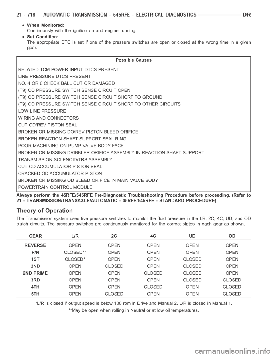
The Transmission system uses five pressure switches to monitor the fluid pressure in the LR, 2C, 4C, UD, and OD
clutch circuits. The pressure switches are continuously monitored for the correct states in each gear as shown.
GEAR L/R 2C 4C UD OD
REVERSEOPEN OPEN OPEN OPEN OPEN
P/NCLOSED** OPEN OPEN OPEN OPEN
1STCLOSED* OPEN OPEN CLOSED OPEN
2NDOPEN CLOSED OPEN CLOSED OPEN
2ND PRIMEOPEN OPEN CLOSED CLOSED OPEN
3RDOPEN OPEN OPEN CLOSED CLOSED
4THOPEN OPEN CLOSED OPEN CLOSED
5THOPEN CLOSED OPEN OPEN CLOSED
*L/R is closed if output speed is below 100 rpm in Drive and Manual 2. L/R is closed in Manual 1.
**May be open when rolling in Neutral or at low oil temperatures.
Page 3256 of 5267
When Monitored:
Continuously with the ignition on and engine running.
Set Condition:
This DTC is set if the UD pressure switch is in the wrong state for the currentgear. For example, this code
would be set if the UD pressure switch remained off while the transmission was in second gear.
Possible Causes
RELATED TCM POWER INPUT DTCS PRESENT
LOW FLUID LEVEL
NO. 2 CHECK BALL CUT OR DAMAGED
LOW LINE PRESSURE
CRACKED OR MIS-INSTALLED SUMP FILTER OR SEAL
STICKING MAIN REGULATOR VALVE IN PUMP VALVE BODY
(T29) UD PRESSURE SWITCH SENSE CIRCUIT OPEN
(T29) UD PRESSURE SWITCH CIRCUIT SHORT TO GROUND
(T29) UD PRESSURE SWITCH SENSE CIRCUIT SHORT TO ANOTHER CIRCUITS
TRANSMISSION SOLENOID/TRS ASSEMBLY
POWERTRAIN CONTROL MODULE
Always perform the 45RFE/545RFE Pre-Diagnostic Troubleshooting Procedure before proceeding. (Refer to
21 - TRANSMISSION/TRANSAXLE/AUTOMATIC - 45RFE/545RFE - STANDARD PROCEDURE)
Theory of Operation
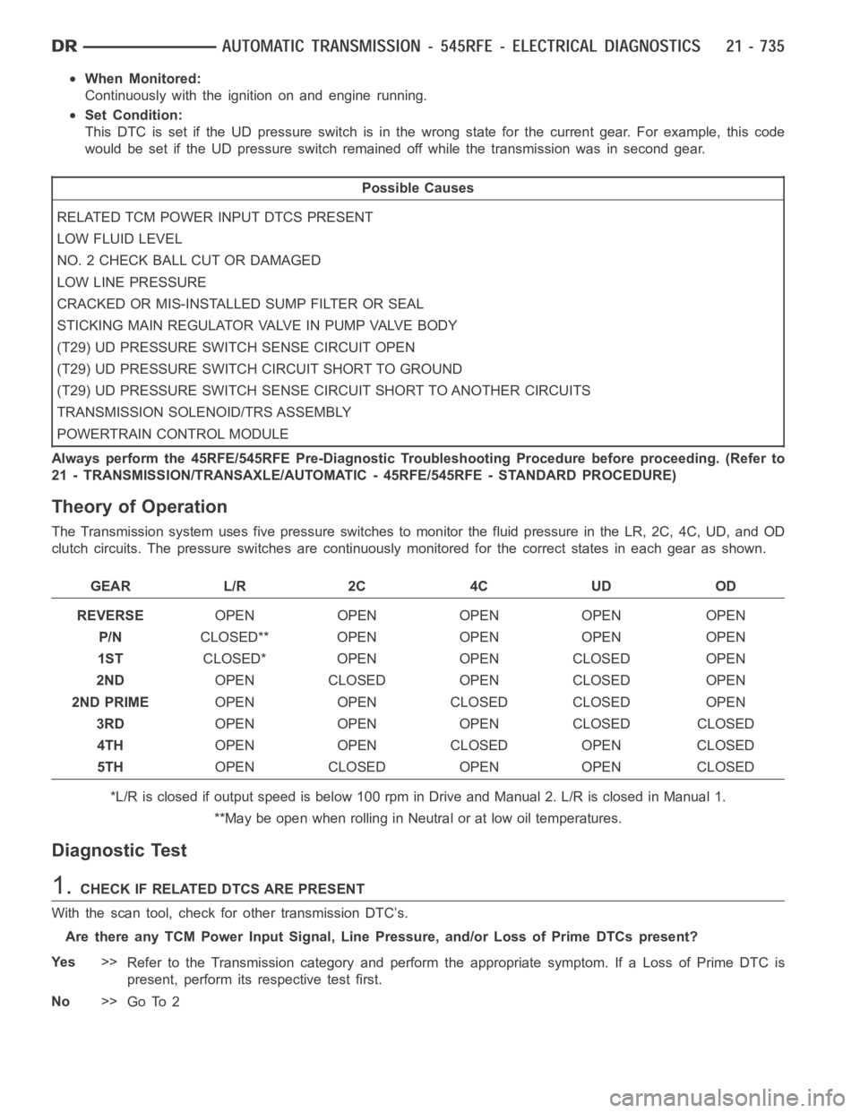
The Transmission system uses five pressure switches to monitor the fluid pressure in the LR, 2C, 4C, UD, and OD
clutch circuits. The pressure switches are continuously monitored for the correct states in each gear as shown.
GEAR L/R 2C 4C UD OD
REVERSEOPEN OPEN OPEN OPEN OPEN
P/NCLOSED** OPEN OPEN OPEN OPEN
1STCLOSED* OPEN OPEN CLOSED OPEN
2NDOPEN CLOSED OPEN CLOSED OPEN
2ND PRIMEOPEN OPEN CLOSED CLOSED OPEN
3RDOPEN OPEN OPEN CLOSED CLOSED
4THOPEN OPEN CLOSED OPEN CLOSED
5THOPEN CLOSED OPEN OPEN CLOSED
*L/R is closed if output speed is below 100 rpm in Drive and Manual 2. L/R is closed in Manual 1.
**May be open when rolling in Neutral or at low oil temperatures.
Diagnostic Test
1.CHECK IF RELATED DTCS ARE PRESENT
With the scan tool, check for other transmission DTC’s.
Are there any TCM Power Input Signal, Line Pressure, and/or Loss of Prime DTCs present?
Ye s>>
Refer to the Transmission category and perform the appropriate symptom. If a Loss of Prime DTC is
present, perform its respective test first.
No>>
Go To 2
Page 3289 of 5267
P0944-LOSS OF HYDRAULIC PUMP PRIME
For a complete wiring diagramRefer to Section 8W
When Monitored:
If the transmission is slipping in any forward gear and all the pressure switches are not indicating pressure, a
loss of prime test is run.
Set Condition:
If the transmission begins to slip in a forward gear and all the pressure switch(s) that should be closed are
open a loss of prime test begins. Available elements are turned on by the PCMto see if pump prime exists.
The DTC sets if no pressure switch(s) respond.
Possible Causes
SHIFT LEVER OUT OF ADJUSTMENT
IMPROPER FLUID LEVEL
CRACKED OR IMPROPERLY INSTALLED PRIMARY OIL FILTER OR SEAL
LOOSE COOLER RETURN FILTER
STUCK OR STICKING MAIN REGULATOR VALVE
TRANSMISSION OIL PUMP
Always perform the 45RFE/545RFE Pre-Diagnostic Troubleshooting procedure before proceeding. (Refer to
21 - TRANSMISSION/TRANSAXLE/AUTOMATIC - 45RFE/545RFE - STANDARD PROCEDURE)
Theory of Operation
The Loss of prime test is used to prevent transmission defaults and erroneous fault codes during temporary loss of
pump prime that may occur with low transmission fluid under severe brakingconditions, start-up, etc. and to point
towards more subtle problems such as a plugged or cracked oil filter.
The Loss of Prime DTC is set by a loss of hydraulic pressure in the transmission system. This condition, if sus-
tained, will result in the vehicle being unable to move.
Diagnostic Test
1.SHIFT LEVER POSITION TEST
Using the scan tool, perform a Shift Lever Position test. Follow the instructions on the scan tool.
Did the Shift Lever Position Test pass?
Ye s>>
Go To 2
No>>
Refer to the Transmission category and perform the appropriate symptom.
Perform 45RFE/545RFE TRANSMISSION VERIFICATION TEST - VER 1. (Refer to 21- TRANSMIS-
SION/TRANSAXLE/AUTOMATIC - 45RFE/545RFE - STANDARD PROCEDURE)
2.CHECK TO SEE IF DTC P0944 IS CURRENT
Place the gear selector in Park.
Start the engine.
The transmission must be at operating temperature prior to checking pressure. A cold transmission will give higher
readings.
Run the engine at 1500 RPM.
With the scan tool, monitor the Transmission Line Pressure.
Does the Line Pressure match the Desired Line Pressure within ± 5 psi?
No>>
Go To 6
Ye s>>
Go To 3
Page 3370 of 5267
line pressure reading should match the gauge reading within ±10 psi.
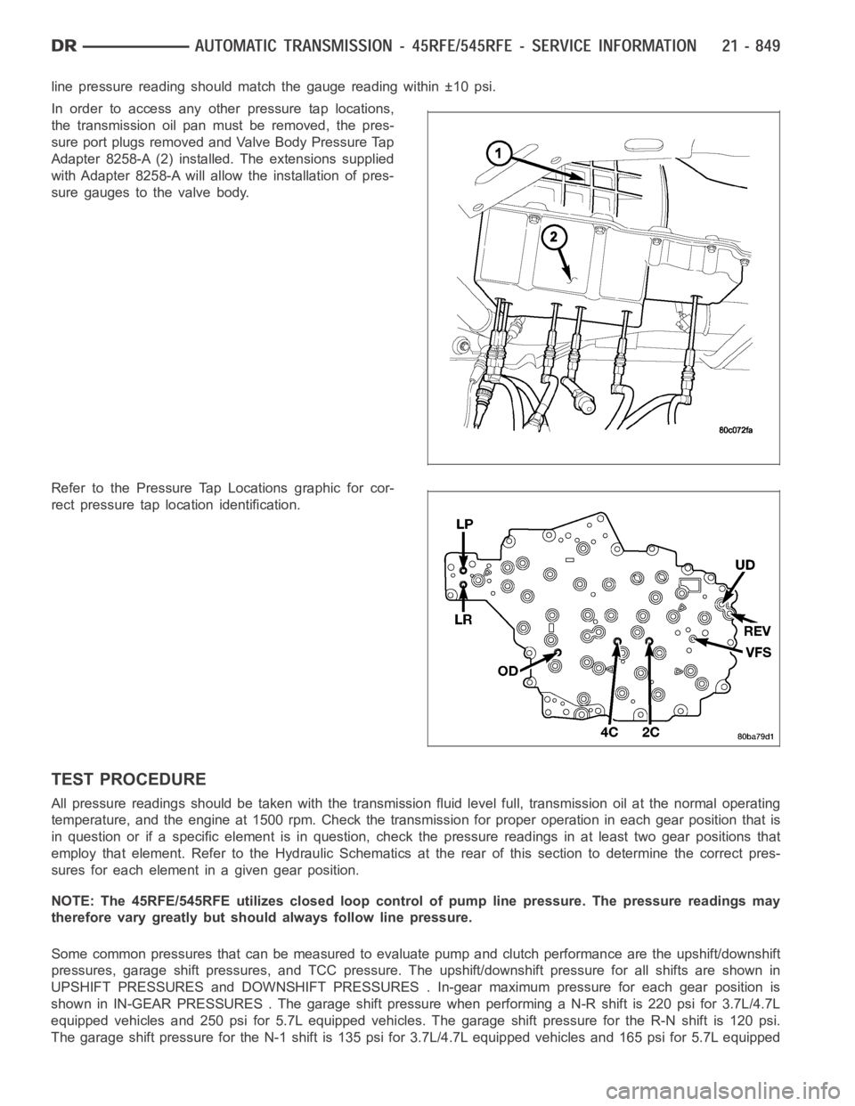
In order to access any other pressure tap locations,
the transmission oil pan must be removed, the pres-
sure port plugs removed and Valve Body Pressure Tap
Adapter 8258-A (2) installed. The extensions supplied
with Adapter 8258-A will allow the installation of pres-
sure gauges to the valve body.
Refer to the Pressure Tap Locations graphic for cor-
rect pressure tap location identification.
TEST PROCEDURE
All pressure readings should be taken with the transmission fluid level full, transmission oil at the normal operating
temperature, and the engine at 1500 rpm. Check the transmission for properoperation in each gear position that is
in question or if a specific element is in question, check the pressure readings in at least two gear positions that
employ that element. Refer to the Hydraulic Schematics at the rear of this section to determine the correct pres-
sures for each element in a given gear position.
NOTE: The 45RFE/545RFE utilizes closed loop control of pump line pressure. The pressure readings may
therefore vary greatly but should always follow line pressure.
Some common pressures that can be measured to evaluate pump and clutch performance are the upshift/downshift
pressures, garage shift pressures, and TCC pressure. The upshift/downshift pressure for all shifts are shown in
UPSHIFT PRESSURES and DOWNSHIFT PRESSURES . In-gear maximum pressure foreach gear position is
shown in IN-GEAR PRESSURES . The garageshift pressure when performing a N-R shift is 220 psi for 3.7L/4.7L
equipped vehicles and 250 psi for 5.7L equipped vehicles. The garage shiftpressure for the R-N shift is 120 psi.
The garage shift pressure for the N-1 shift is 135 psi for 3.7L/4.7L equipped vehicles and 165 psi for 5.7L equipped
Page 3431 of 5267

In either case, air bubbles can cause overheating and/or fluid oxidation,and varnishing. This can interfere with nor-
mal valve, clutch, and accumulator operation. Foaming can also result in fluid escaping from the transmission vent
where it may be mistaken for a leak.
After the fluid has been checked, seat the dipstick fully to seal out water and dirt.
The transmission has a dipstick to check oil level. It is located on the right side of the engine. Be sure to wipe all
dirt from dipstick handle before removing.
The torque converter fills in both the P(PARK) and N (NEUTRAL) positions. Place the selector lever in P (PARK)
to be sure that the fluid level check is accurate.The engine should be running at idle speed for at least one
minute, with the vehicle on level ground.At normal operating temperature (approximately 82° C. or 180° F), the
fluid level is correct if it is in the HOT region (cross-hatched area) on theoil level indicator. The fluid level will be
approximately at the upper COLD hole of the dipstick at 21° C (70° F) fluid temperature.
NOTE: Engine and Transmission should be at normal operating temperature before performing this proce-
dure.
1. Start engine and apply parking brake.
2. Shift the transmission into DRIVE for approximately 2 seconds.
3. Shift the transmission into REVERSE for approximately 2 seconds.
4. Shift the transmission into PARK.
5. Hook up scan tool andselect transmission.
6. Select sensors.
7. Read the transmission temperature value.
8. Compare the fluid temperature value with the chart.
9. Adjust transmission fluid level shown on the dipstick according to the Transmission Fluid Temperature Chart.
NOTE: After adding any fluid to the transmission, wait a minimum of 2 minutes for the oil to fully drain from
the fill tube into the transmission before rechecking the fluid level.
10. Check transmission for leaks.
Page 3463 of 5267
OPERATION
As the torque converter rotates, the converter hub rotates the oil pump drive gear. As the drive gear rotates both
driven gears, a vacuum is created when the gear teeth come out of mesh. This suction draws fluid through the
pump inlet from the oil pan. As the gear teeth come back into mesh, pressurized fluid is forced into the pump outlet
and to the oil pump valves.
At low speeds, both sides of the pump supply fluid to the transmission. As the speed of the torque converter
increases, the flow from both sides increases until the flow from the primary side alone is sufficient to meet system
demands. At this point, the check valve located between the two pumps closes. The secondary side is shut down
and the primary side supplies all the fluid to the transmission.
CONVERTER CLUTCH SWITCH VALVE
The converter clutch switch valve is used to control the hydraulic pressure supplied to the front (OFF) side of the
torque converter clutch.
CONVERTER CLUTCH REGULATOR VALVE
The converter clutch regulator valve is used to control the hydraulic pressure supplied to the back (ON) side of the
torque converter clutch.
TORQUE CONVERTER LIMIT VALVE
The torque converter limit valve serves to limit the available line pressure to the torque converter clutch.
STANDARD PROCEDURE - OIL PUMP VOLUME CHECK
Measuring the oil pump output volume will determine if sufficient oil flowto the transmission oil cooler exists, and
whether or not an internal transmission failure is present.
Verify that the transmission fluid is at the proper level. Refer to the Fluid Level Check procedure in this section. If
necessary, fill the transmission to the proper level with Mopar
ATF +4, Automatic Transmission Fluid.
1. Disconnect theTo coolerline at the cooler inlet and place a collecting container under the disconnected line.
CAUTION: With the fluid set at the proper level, fluid collection should not exceed (1) quart or internal dam-
age to the transmission may occur.
2. Run the engineat 1800 rpm, with the shift selector in neutral. Verify that the transmission fluid temperature is
below 104.5° C (220° F) for this test.
3. If one quart of transmission fluid is collected in the container in 30 seconds or less, oil pump flow volume is
within acceptable limits. If fluid flow is intermittent, or it takes more than 30 seconds to collect one quart of fluid,
refer to the Hydraulic Pressure tests in this section for further diagnosis.
4. Re-connect theTo c o o l e rline to the transmission cooler inlet.
5. Refill the transmission to proper level.
Page 3482 of 5267
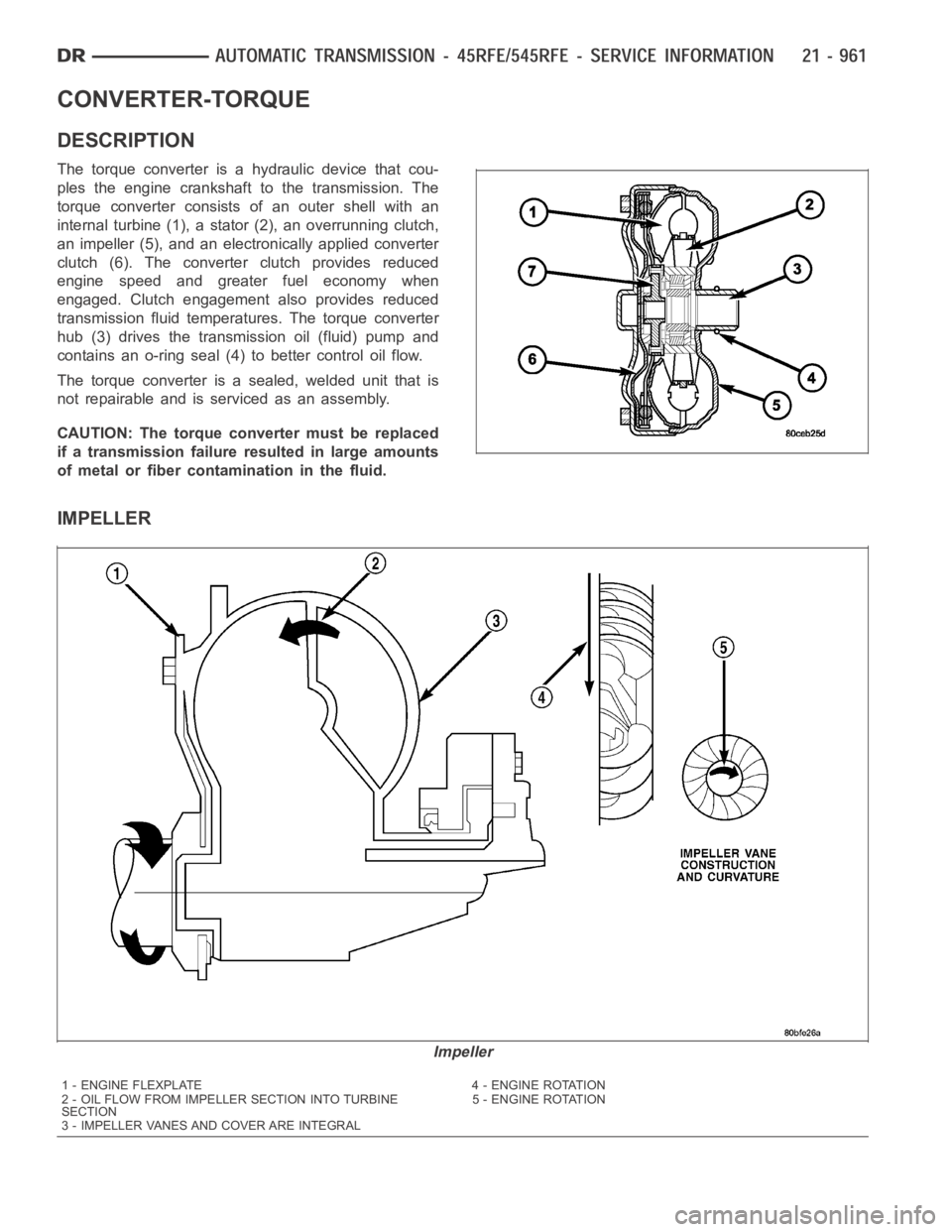
CONVERTER-TORQUE
DESCRIPTION
The torque converter is a hydraulic device that cou-
ples the engine crankshaft to the transmission. The
torque converter consists of an outer shell with an
internal turbine (1), a stator (2), an overrunning clutch,
an impeller (5), and an electronically applied converter
clutch (6). The converterclutch provides reduced
engine speed and greater fuel economy when
engaged. Clutch engagement also provides reduced
transmission fluid temperatures. The torque converter
hub (3) drives the transmission oil (fluid) pump and
contains an o-ring seal (4) to better control oil flow.
The torque converter is a sealed, welded unit that is
not repairable and is serviced as an assembly.
CAUTION: The torque converter must be replaced
if a transmission failure resulted in large amounts
of metal or fiber contamination in the fluid.
IMPELLER
Impeller
1 - ENGINE FLEXPLATE 4 - ENGINE ROTATION
2 - OIL FLOW FROM IMPELLER SECTION INTO TURBINE
SECTION5 - ENGINE ROTATION
3 - IMPELLER VANES AND COVER ARE INTEGRAL
Page 3511 of 5267
Theory of Operation
The Transmission Temperature Sensor is used to sense when the transmissiontemperatureistoohotortoocoldto
operate overdrive and/or the torque convertor clutch. When the transmission sensor detects a temperature below 0°
C (32° F), overdrive and the torque convertor clutch are disabled. When thedetected temperature is above 127° C
(260° F), overdrive is disabled and 3rd gear with TCC is engaged, this strategy is used to increase transmission
fluid flow to help cool the transmission.
When Monitored:
Continuously with the ignition on and the engine running.
Set Condition:
The DTC will set after two consecutive trips in which the transmission oil temperature is greater than 5° C (40°
F) and the transmission oil temperature does not rise more than 8° C (16° F) after 20 minutes of run time with
a vehicle speed greater than 48 Kmh (30 mph). The DTC will also set if the engine temperature is greater than
38° C (100° F) with the transmission oil temperature greater than 127° C (260° F).
Possible Causes
OTHER TRANSMISSION DTC’S SET
INTERMITTENT TRANSMISSION TEMPERATURE SENSOR
TRANSMISSION TEMPERATURE SENSOR
Always perform the Pre-Diagnostic Troubleshooting procedure before proceeding. (Refer to 21 - TRANSMIS-
SION/TRANSAXLE/AUTOMATIC - 48RE - STANDARD PROCEDURE)
Diagnostic Test
1.CHECK IF THE DTC IS CURRENT
Ignition on, engine not running.
With the scan tool, read Engine DTCs.
Record the Freeze Frame data for the reported DTC.
With the scan tool, erase DTCs.
Turn the ignition off to the lock position.
Using the Freeze Frame data recorded earlier, try to duplicate the conditions in which the DTC originally set.
NOTE: It may be necessary to road test the vehicle to duplicate the originalset conditions.
With the scan tool, read Engine DTCs.
Did the DTC reset?
Ye s>>
Go To 2
No>>
Go To 6
2.CHECK FOR OTHER TRANSMISSION DTCS
Does the scan tool show any Park/Neutral DTCs?
Ye s>>
Refer to the Transmission category and perform the appropriate symptom(s).
No>>
Go To 3