2006 DODGE RAM SRT-10 oil temperature
[x] Cancel search: oil temperaturePage 3757 of 5267
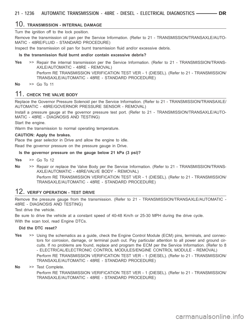
10.TRANSMISSION - INTERNAL DAMAGE
Turn the ignition off to the lock position.
Remove the transmission oil pan per the Service Information. (Refer to 21 -TRANSMISSION/TRANSAXLE/AUTO-
MATIC - 48RE/FLUID - STANDARD PROCEDURE)
Inspect the transmission oil pan for burnt transmission fluid and/or excessive debris.
Is the transmission fluid burnt and/or contain excessive debris?
Ye s>>
Repair the internal transmission per the Service Information. (Refer to 21 - TRANSMISSION/TRANS-
AXLE/AUTOMATIC - 48RE - REMOVAL)
Perform RE TRANSMISSION VERIFICATION TEST VER - 1 (DIESEL). (Refer to 21 - TRANSMISSION/
TRANSAXLE/AUTOMATIC - 48RE - STANDARD PROCEDURE)
No>>
Go To 11
11 .CHECK THE VALVE BODY
Replace the Governor Pressure Solenoid per the Service Information. (Refer to 21 - TRANSMISSION/TRANSAXLE/
AUTOMATIC - 48RE/GOVERNOR PRESSURE SENSOR - REMOVAL)
Install a pressure gauge at the governor pressure test port. (Refer to 21 - TRANSMISSION/TRANSAXLE/AUTO-
MATIC - 48RE - DIAGNOSIS AND TESTING)
Start the engine.
Warm the transmission to normal operating temperature.
CAUTION: Apply the brakes.
Place the gear selector in Drive and allow the engine to idle.
Read the governor pressure on the pressure gauge in Drive.
Is the governor pressure on the gauge below 21 kPa (3 psi)?
Ye s>>
Go To 12
No>>
Repair or replace the Valve Body per the Service Information. (Refer to 21 -TRANSMISSION/TRANS-
AXLE/AUTOMATIC - 48RE/VALVE BODY - REMOVAL)
Perform RE TRANSMISSION VERIFICATION TEST VER - 1 (DIESEL). (Refer to 21 - TRANSMISSION/
TRANSAXLE/AUTOMATIC - 48RE - STANDARD PROCEDURE)
12.VERIFY OPERATION - TEST DRIVE
Remove the pressure gauge from the transmission. (Refer to 21 - TRANSMISSION/TRANSAXLE/AUTOMATIC -
48RE - DIAGNOSIS AND TESTING)
Test drive the vehicle.
Be sure to drive the vehicle at a constant speed of 40-48 Km/h or 25-30 MPH during the drive cycle.
With the scan tool, read Engine DTCs.
Did the DTC reset?
Ye s>>
Using the schematics as a guide, check the Engine Control Module (ECM) pins, terminals, and connec-
tors for corrosion, damage, or terminal push out. Pay particular attentiontoallpowerandgroundcir-
cuits. If no problems are found, replace and program the ECM per the ServiceInformation. (Refer to 8
- ELECTRICAL/ELECTRONIC CONTROL MODULES/ENGINE CONTROL MODULE - REMOVAL)
Perform RE TRANSMISSION VERIFICATION TEST VER - 1 (DIESEL). (Refer to 21 - TRANSMISSION/
TRANSAXLE/AUTOMATIC - 48RE - STANDARD PROCEDURE)
No>>
Te s t C o m p l e t e .
Perform RE TRANSMISSION VERIFICATION TEST VER - 1 (DIESEL). (Refer to 21 - TRANSMISSION/
TRANSAXLE/AUTOMATIC - 48RE - STANDARD PROCEDURE)
Page 3760 of 5267
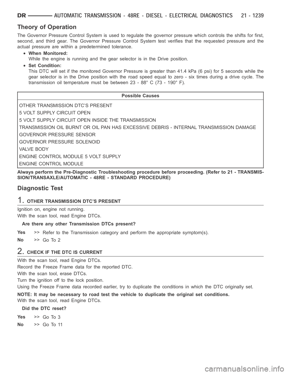
Theory of Operation
The Governor Pressure Control System is used to regulate the governor pressure which controls the shifts for first,
second, and third gear. The Governor Pressure Control System test verifies that the requested pressure and the
actual pressure are within a predetermined tolerance.
When Monitored:
While the engine is running and the gear selector is in the Drive position.
Set Condition:
This DTC will set if the monitored Governor Pressure is greater than 41.4 kPa(6psi)for5secondswhilethe
gear selector is in the Drive position with the road speed equal to zero - sixtimes during a drive cycle. The
transmission oil temperature must be between 23 - 88° C (73 - 190° F).
Possible Causes
OTHER TRANSMISSION DTC’S PRESENT
5 VOLT SUPPLY CIRCUIT OPEN
5 VOLT SUPPLY CIRCUIT OPEN INSIDE THE TRANSMISSION
TRANSMISSION OIL BURNT OR OIL PAN HAS EXCESSIVE DEBRIS - INTERNAL TRANSMISSION DAMAGE
GOVERNOR PRESSURE SENSOR
GOVERNOR PRESSURE SOLENOID
VA LV E B O D Y
ENGINE CONTROL MODULE 5 VOLT SUPPLY
ENGINE CONTROL MODULE
Always perform the Pre-Diagnostic Troubleshooting procedure before proceeding. (Refer to 21 - TRANSMIS-
SION/TRANSAXLE/AUTOMATIC - 48RE - STANDARD PROCEDURE)
Diagnostic Test
1.OTHER TRANSMISSION DTC’S PRESENT
Ignition on, engine not running.
With the scan tool, read Engine DTCs.
Are there any other Transmission DTCs present?
Ye s>>
Refer to the Transmission category and perform the appropriate symptom(s).
No>>
Go To 2
2.CHECK IF THE DTC IS CURRENT
With the scan tool, read Engine DTCs.
Record the Freeze Frame data for the reported DTC.
With the scan tool, erase DTCs.
Turn the ignition off to the lock position.
Using the Freeze Frame data recorded earlier, try to duplicate the conditions in which the DTC originally set.
NOTE: It may be necessary to road test the vehicle to duplicate the originalset conditions.
With the scan tool, read Engine DTCs.
Did the DTC reset?
Ye s>>
Go To 3
No>>
Go To 11
Page 3761 of 5267
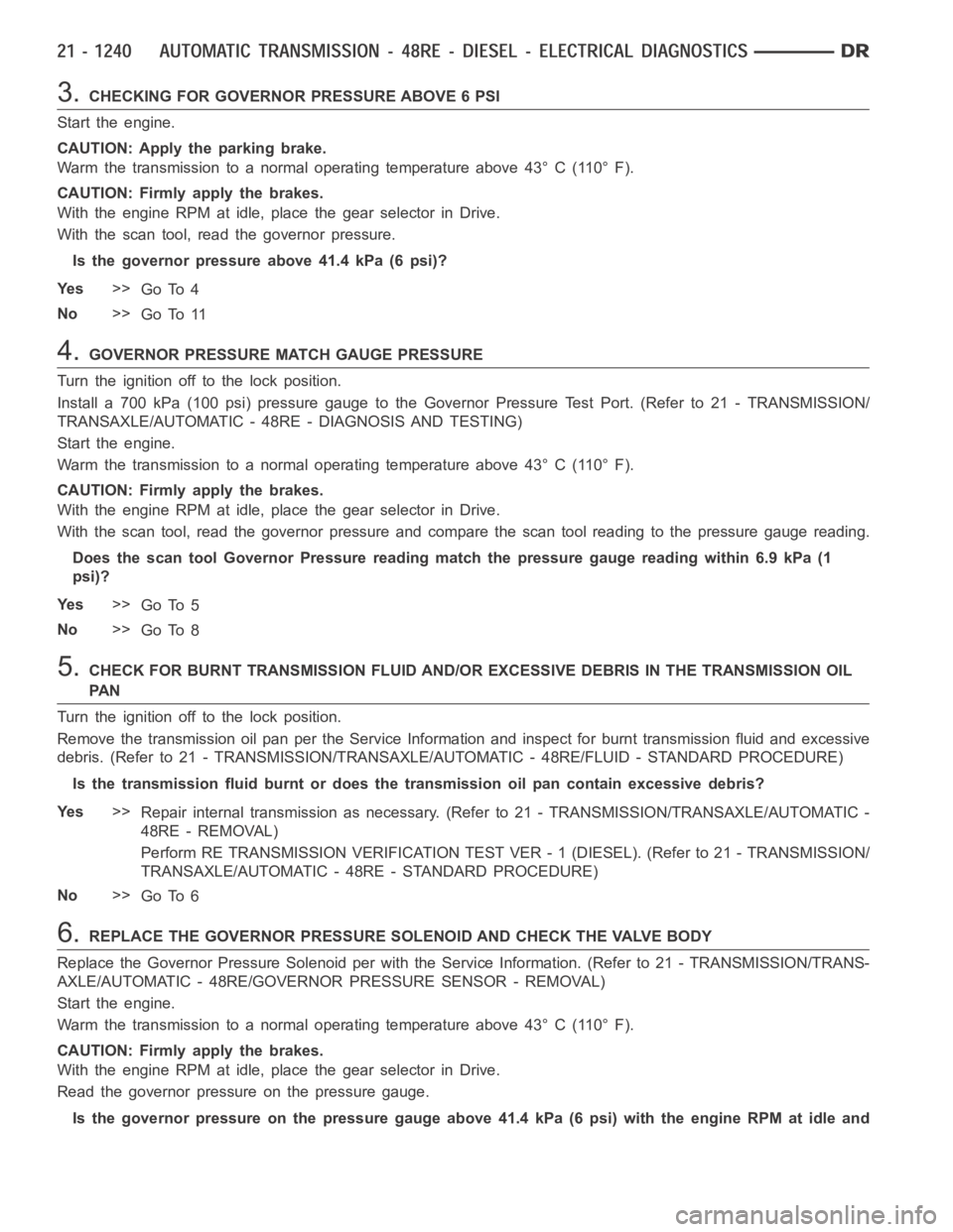
3.CHECKING FOR GOVERNOR PRESSURE ABOVE 6 PSI
Start the engine.
CAUTION: Apply the parking brake.
Warm the transmission to a normal operating temperature above 43° C (110° F).
CAUTION: Firmly apply the brakes.
With the engine RPM at idle, place the gear selector in Drive.
With the scan tool, read the governor pressure.
Is the governor pressure above 41.4 kPa (6 psi)?
Ye s>>
Go To 4
No>>
Go To 11
4.GOVERNOR PRESSURE MATCH GAUGE PRESSURE
Turn the ignition off to the lock position.
Install a 700 kPa (100 psi) pressure gauge to the Governor Pressure Test Port. (Refer to 21 - TRANSMISSION/
TRANSAXLE/AUTOMATIC - 48RE - DIAGNOSIS AND TESTING)
Start the engine.
Warm the transmission to a normal operating temperature above 43° C (110° F).
CAUTION: Firmly apply the brakes.
With the engine RPM at idle, place the gear selector in Drive.
With the scan tool, read the governor pressure and compare the scan tool reading to the pressure gauge reading.
Does the scan tool Governor Pressure reading match the pressure gauge reading within 6.9 kPa (1
psi)?
Ye s>>
Go To 5
No>>
Go To 8
5.CHECK FOR BURNT TRANSMISSION FLUID AND/OR EXCESSIVE DEBRIS IN THE TRANSMISSION OIL
PA N
Turn the ignition off to the lock position.
Remove the transmission oil pan per the Service Information and inspect for burnt transmission fluid and excessive
debris. (Refer to 21 - TRANSMISSION/TRANSAXLE/AUTOMATIC - 48RE/FLUID - STANDARD PROCEDURE)
Is the transmission fluid burnt or does the transmission oil pan contain excessive debris?
Ye s>>
Repair internal transmission as necessary. (Refer to 21 - TRANSMISSION/TRANSAXLE/AUTOMATIC -
48RE - REMOVAL)
Perform RE TRANSMISSION VERIFICATION TEST VER - 1 (DIESEL). (Refer to 21 - TRANSMISSION/
TRANSAXLE/AUTOMATIC - 48RE - STANDARD PROCEDURE)
No>>
Go To 6
6.REPLACE THE GOVERNOR PRESSURE SOLENOID AND CHECK THE VALVE BODY
Replace the Governor Pressure Solenoid per with the Service Information.(Refer to 21 - TRANSMISSION/TRANS-
AXLE/AUTOMATIC - 48RE/GOVERNOR PRESSURE SENSOR - REMOVAL)
Start the engine.
Warm the transmission to a normal operating temperature above 43° C (110° F).
CAUTION: Firmly apply the brakes.
With the engine RPM at idle, place the gear selector in Drive.
Read the governor pressure on the pressure gauge.
Is the governor pressure on the pressure gauge above 41.4 kPa (6 psi) with the engine RPM at idle and
Page 3767 of 5267
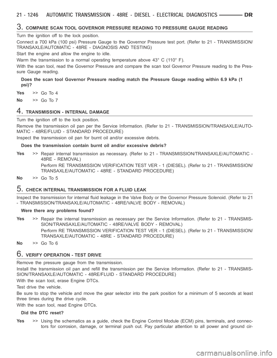
3.COMPARE SCAN TOOL GOVERNOR PRESSURE READING TO PRESSURE GAUGE READING
Turn the ignition off to the lock position.
Connect a 700 kPa (100 psi) Pressure Gauge to the Governor Pressure test port. (Refer to 21 - TRANSMISSION/
TRANSAXLE/AUTOMATIC - 48RE - DIAGNOSIS AND TESTING)
Start the engine and allow the engine to idle.
Warm the transmission to a normal operating temperature above 43° C (110° F).
With the scan tool, read the Governor Pressure and compare the scan tool Governor Pressure reading to the Pres-
sure Gauge reading.
Does the scan tool Governor Pressure reading match the Pressure Gauge reading within 6.9 kPa (1
psi)?
Ye s>>
Go To 4
No>>
Go To 7
4.TRANSMISSION - INTERNAL DAMAGE
Turn the ignition off to the lock position.
Remove the transmission oil pan per the Service Information. (Refer to 21 -TRANSMISSION/TRANSAXLE/AUTO-
MATIC - 48RE/FLUID - STANDARD PROCEDURE)
Inspect the transmission oil pan for burnt oil and/or excessive debris.
Does the transmission contain burnt oil and/or excessive debris?
Ye s>>
Repair internal transmission as necessary. (Refer to 21 - TRANSMISSION/TRANSAXLE/AUTOMATIC -
48RE - REMOVAL)
Perform RE TRANSMISSION VERIFICATION TEST VER - 1 (DIESEL). (Refer to 21 - TRANSMISSION/
TRANSAXLE/AUTOMATIC - 48RE - STANDARD PROCEDURE)
No>>
Go To 5
5.CHECK INTERNAL TRANSMISSION FOR A FLUID LEAK
Inspect the transmission for internal fluid leakage in the Valve Body or the Governor Pressure Solenoid. (Refer to 21
- TRANSMISSION/TRANSAXLE/AUTOMATIC - 48RE/VALVE BODY - REMOVAL)
Were there any problems found?
Ye s>>
Repair the internal transmission as necessary per the Service Information. (Refer to 21 - TRANSMIS-
SION/TRANSAXLE/AUTOMATIC - 48RE/VALVE BODY - REMOVAL)
Perform RE TRANSMISSION VERIFICATION TEST VER - 1 (DIESEL). (Refer to 21 - TRANSMISSION/
TRANSAXLE/AUTOMATIC - 48RE - STANDARD PROCEDURE)
No>>
Go To 6
6.VERIFY OPERATION - TEST DRIVE
Remove the pressure gauge from the transmission.
Install the transmission oil pan and refill the transmission per the Service Information. (Refer to 21 - TRANSMIS-
SION/TRANSAXLE/AUTOMATIC - 48RE/FLUID - STANDARD PROCEDURE)
With the scan tool, erase Engine DTCs.
Test drive the vehicle.
Be sure to stop the vehicle and move the gear selector into the park positionfor a minimum of 5 seconds at least
three times during the drive cycle.
With the scan tool, read Engine DTCs.
Did the DTC reset?
Ye s>>
Using the schematics as a guide, check the Engine Control Module (ECM) pins, terminals, and connec-
tors for corrosion, damage, or terminal push out. Pay particular attentiontoallpowerandgroundcir-
Page 3792 of 5267
OPERATION
The application of each driving or holding component is controlled by the valve body based upon the manual lever
position, throttle pressure, and governor pressure. The governor pressure is a variable pressure input to the valve
body and is one of the signals that a shift is necessary. First through fourth gear are obtained by selectively apply-
ing and releasing the different clutches and bands. Engine power is thereby routed to the various planetary gear
assemblies which combine with the overrunning clutch assemblies to generate the different gear ratios. The torque
converter clutch is hydraulically applied and is released when fluid is vented from the hydraulic circuit by the torque
converter control (TCC) solenoid on the valve body. The torque converter clutch is controlled by the Powertrain
Control Module (PCM). The torque converter clutch engages in fourth gear,and in third gear under various condi-
tions, such as when the O/D switch is OFF, when the vehicle is cruising on a level surface after the vehicle has
warmed up. The torque converter clutch can also be engaged in the MANUAL SECOND gear position if high trans-
mission temperatures are sensed by the PCM. The torque converter clutch will disengage momentarily when an
increase in engine load is sensed by the PCM, such as when the vehicle beginsto go uphill or the throttle pressure
is increased. The torque converter clutch feature increases fuel economyand reduces the transmission fluid tem-
perature.
Since the overdrive clutch is applied in fourth gear only and the direct clutch is applied in all ranges except fourth
gear, the transmission operation for park, neutral, and first through third gear will be described first. Once these
powerflows are described, the third to fourth shift sequence will be described.
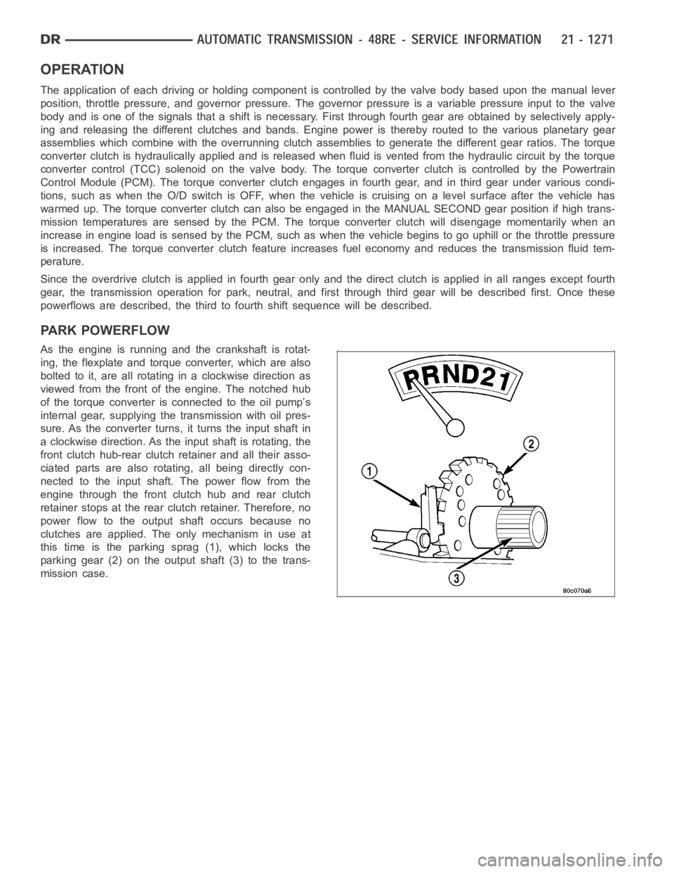
PARK POWERFLOW
As the engine is running and the crankshaft is rotat-
ing, the flexplate and torque converter, which are also
bolted to it, are all rotating in a clockwise direction as
viewed from the front of the engine. The notched hub
of the torque converter is connected to the oil pump’s
internal gear, supplying the transmission with oil pres-
sure. As the converter turns, it turns the input shaft in
a clockwise direction. As the input shaft is rotating, the
front clutch hub-rear clutch retainer and all their asso-
ciated parts are also rotating, all being directly con-
nected to the input shaft. The power flow from the
engine through the front clutch hub and rear clutch
retainer stops at the rear clutch retainer. Therefore, no
power flow to the output shaft occurs because no
clutches are applied. The only mechanism in use at
this time is the parking sprag (1), which locks the
parking gear (2) on the output shaft (3) to the trans-
mission case.
Page 3869 of 5267
OPERATION
Compensation is required for performance variations of two of the input devices. Though the slope of the transfer
functions is tightly controlled, offset may vary due to various environmental factors or manufacturing tolerances.
The pressure transducer is affected by barometric pressure as well as temperature. Calibration of the zero pressure
offset is required to compensate for shifting output due to these factors.
Normal calibration will be performed when sump temperature is above 50 degrees F, or in the absence of sump
temperature data, after the first 10 minutes of vehicle operation. Calibration of the pressure transducer offset occurs
each time the output shaft speed falls below 200 RPM. Calibration shall be repeated each 3 seconds the output
shaft speed is below 200 RPM. A 0.5 second pulse of 95% duty cycle is applied to the governor pressure solenoid
valve and the transducer output is read during this pulse. Averaging of thetransducer signal isnecessary to reject
electrical noise.
Under cold conditions (below 50 degrees F sump), the governor pressure solenoid valve response may be too slow
to guarantee 0 psi during the 0.5 second calibration pulse. Calibration pulses are continued during this period, how-
ever the transducer output valves are discarded. Transducer offset must be read at key-on, under conditions which
promote a stable reading. This value is retained and becomes the offset during the
coldperiod of operation.
GOVERNOR PRESSURE SOLENOID VALVE
The inlet side of the solenoid valve is exposed to normal transmission linepressure. The outlet side of the valve
leads to the valve body governor circuit.
The solenoid valve regulates line pressure to produce governor pressure.Theaveragecurrentsuppliedtothesole-
noid controls governor pressure. One amp current produces zero kPa/psi governor pressure. Zero amps sets the
maximum governor pressure.
The powertrain control module (PCM) turns on the trans control relay whichsupplies electrical power to the solenoid
valve. Operating voltage is 12 volts (DC). The PCM controls the ground sideof the solenoid using the governor
pressure solenoidcontrol circuit.
GOVERNOR PRESSURE SENSOR
The sensor output signal provides the necessary feedback to the PCM. This feedback is needed to adequately
control governor pressure.
GOVERNOR BODY AND TRANSFER PLATE
The transfer plate channels line pressure to the solenoid valve through the governor body. It also channels governor
pressure from the solenoid valve to the governor circuit. It is the solenoid valve that develops the necessary gov-
ernor pressure.
GOVERNOR PRESSURE CURVES
LOW TRANSMISSION FLUID TEMPERATURE
When the transmission fluid is cold the conventional governor can delay shifts, resulting in higher than normal shift
speeds and harsh shifts. The electronically controlled low temperature governor pressure curve is higher than nor-
mal to make the transmission shift at normal speeds and sooner. The PCM usesa temperature sensor in the trans-
mission oil sump to determine when low temperature governor pressure is needed.
NORMAL OPERATION
Normal operation is refined through the increased computing power of the PCM and through access to data on
engine operating conditions provided by the PCM that were not available with the previous stand-alone electronic
module. This facilitated the development of a load adaptive shift strategy - the ability to alter the shift schedule in
response to vehicle load condition. One manifestation of this capabilityis grade
huntingprevention - the ability of
the transmission logic to delay an upshift on a grade if the engine does not have sufficient power to maintain speed
in the higher gear. The 3-2 downshift and the potential for hunting betweengears occurs with a heavily loaded
vehicle or on steep grades. When hunting occurs, it is very objectionable because shifts are frequent and accom-
panied by large changes in noise and acceleration.
Page 3875 of 5267
After the fluid has been checked, seat the dipstick fully to seal out water and dirt.
The transmission has a dipstick to check oil level. It is located on the right side of the engine. Be sure to wipe all
dirt from dipstick handle before removing.
Fluid level is checked with the engine running at curb idle speed, the transmissioninNEUTRALandthetransmis-
sion fluid at normal operating temperature.The engine should be running at idle speed for at least one minute,
with the vehicle on level ground.
The transmission fluid level can be checked two ways.
PROCEDURE ONE
1. Transmission fluid must be at normal operating
temperature for accurate fluid level check. Drive
vehicle if necessary to bring fluid temperature up to
normal hot operating temperature of 82°C (180°F).
2. Position vehicle on level surface.
3. Start and run engine at curb idle speed.
4. Apply parking brakes.
5. Shift transmission momentarily into all gear ranges.
Then shift transmission back to NEUTRAL.
6. Clean top of filler tube and dipstick to keep dirt from entering tube.
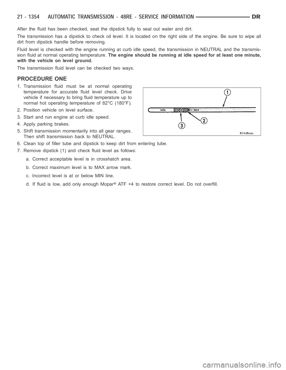
7. Remove dipstick (1) and check fluid level as follows:
a. Correct acceptable level is in crosshatch area.
b. Correct maximum level is to MAX arrow mark.
c. Incorrect level is at or below MIN line.
d. If fluid is low, add only enough Mopar
ATF +4 to restore correct level. Do not overfill.
Page 3876 of 5267

PROCEDURE TWO
1. Start engine and apply parking brake.
2. Shift the transmission into DRIVE for approximately 2 seconds.
3. Shift the transmission into REVERSE for approximately 2 seconds.
4. Shift the transmission into PARK.
5. Hook up DRB
scan tool and select engine.
6. Select sensors.
7. Read the transmission temperature value.
8. Compare the fluid temperature value with the chart.
9. Adjust transmission fluid level shown on the dipstick according to the chart.
NOTE: After adding any fluid to the transmission, wait a minimum of 2 minutes for the oil to fully drain from
the fill tube into the transmission before rechecking the fluid level.
10. Check transmission for leaks.
FLUID AND FILTER REPLACEMENT
For proper service intervals (Refer to LUBRICATION & MAINTENANCE/MAINTENANCE SCHEDULES - DESCRIP-
TION). The service fluid fill after a filter change is approximately 3.8 liters (4.0 quarts).