2006 DODGE RAM SRT-10 oil temperature
[x] Cancel search: oil temperaturePage 2343 of 5267
Fuel enters the system from the electric fuel transfer (lift) pump, which is located inside of the fuel tank and attached
to the fuel tank module (the fuel transfer pump is no longer attached to the engine). Fuel is forced through the fuel
filter element and then enters the Fuel Pump/Gear Pump, which is attached to the rear of the fuel injection pump.
The Fuel Pump/Gear Pump is a low-pressure pump and produce pressures ranging from 551.5 kpa (80 psi) to 1241
kpa (180) psi. Fuel then enters the fuel injection pump. Low pressure fuel is then supplied to the FCA (Fuel Control
Actuator).
The FCA is an electronically controlled solenoid valve. The ECM controls the amount of fuel that enters the high-
pressure pumping chambers by opening and closing the FCA based on a demanded fuel pressure. The FPS (Fuel
Pressure Sensor) on the fuel rail monitors the actual fuel pressure and provides it as an input to the ECM. When
the actuator is opened, the maximum amount of fuel is being supplied to the fuel injection pump. Any fuel that does
not enter the injection pump is directed to the overflow valve. The overflow valve regulates how much excess fuel
is used for lubrication of the pump and how much is returned to the tank through the drain manifold.
Fuel entering the injection pump is pressurized to between 300-1600 bar (4351-23,206 psi) by three radial pumping
chambers. The pressurized fuel is then supplied to the fuel rail.
STANDARD PROCEDURE
WATER DRAINING AT FUEL FILTER
Refer to Fuel Filter/Water Separatorremoval/installation for procedures.
CLEANING FUEL SYSTEM PARTS
CAUTION: Cleanliness cannot be overemphasized when handling or replacingdieselfuelsystemcompo-
nents. This especially includes the fuel injectors, high-pressure fuel lines and fuel injection pump. Very tight
tolerances are used with these parts. Dirt contamination could cause rapid part wear and possible plugging
of fuel injector nozzle tip holes. This in turn could lead to possible engine misfire. Always wash/clean any
fuel system component thoroughly before disassembly and then air dry. Capor cover any open part after
disassembly. Before assembly, examine each part for dirt, grease or othercontaminants and clean if nec-
essary. When installing new parts, lubricate them with clean engine oil orclean diesel fuel only.
FUEL SYSTEM PRIMING
A certain amount of air becomes trappedin the fuel system when fuel system components on the supply and/or
high-pressure side are serviced or replaced. Fuel system priming is accomplished using the electric fuel transfer (lift)
pump.
Servicing or replacing fuel system components will not require fuel systempriming.
The fuel transfer (lift) pump is self-priming: When the key is first turnedon (without cranking engine), the pump
operates for approximately 1 to 2 second and then shuts off (Note: When ambient temperatures are cold enough to
cause the intake air heaters to operate, the fuel lift pump will operate during the entire intake air pre-heat cycle).
The pump will also operate for up to 25 seconds after the starter is quickly engaged, and then disengaged without
allowing the engine to start. The pump shuts off immediately if the key is onand the engine stops running.
1. Turn key to CRANK position and quickly release key to ON position before engine starts. This will operate fuel
transfer pump for approximately 25 seconds.
2. Crank engine. If the engine does not start after 25 seconds, turn key to OFF position, and leave it off for at least
5 seconds. Repeat previous step until engine starts.
3. Fuel system priming is now completed.
4. Attempt to start engine. If engine will not start, proceed to following steps.When engine does start, it may run
erratically and be noisy for a few minutes. This is a normal condition.
CAUTION: Do not engage the starter motor for more than 30 seconds at a time. Allow two minutes between
cranking intervals.
5. Perform previous fuel priming procedure steps using fuel transfer pump. Be sure fuel is present at fuel tank.
6. Crank the engine for 30 seconds at a time to allow fuel system to prime.
Page 2457 of 5267
NOTE: The pitman shaft will not clear the housing if it is not centered.
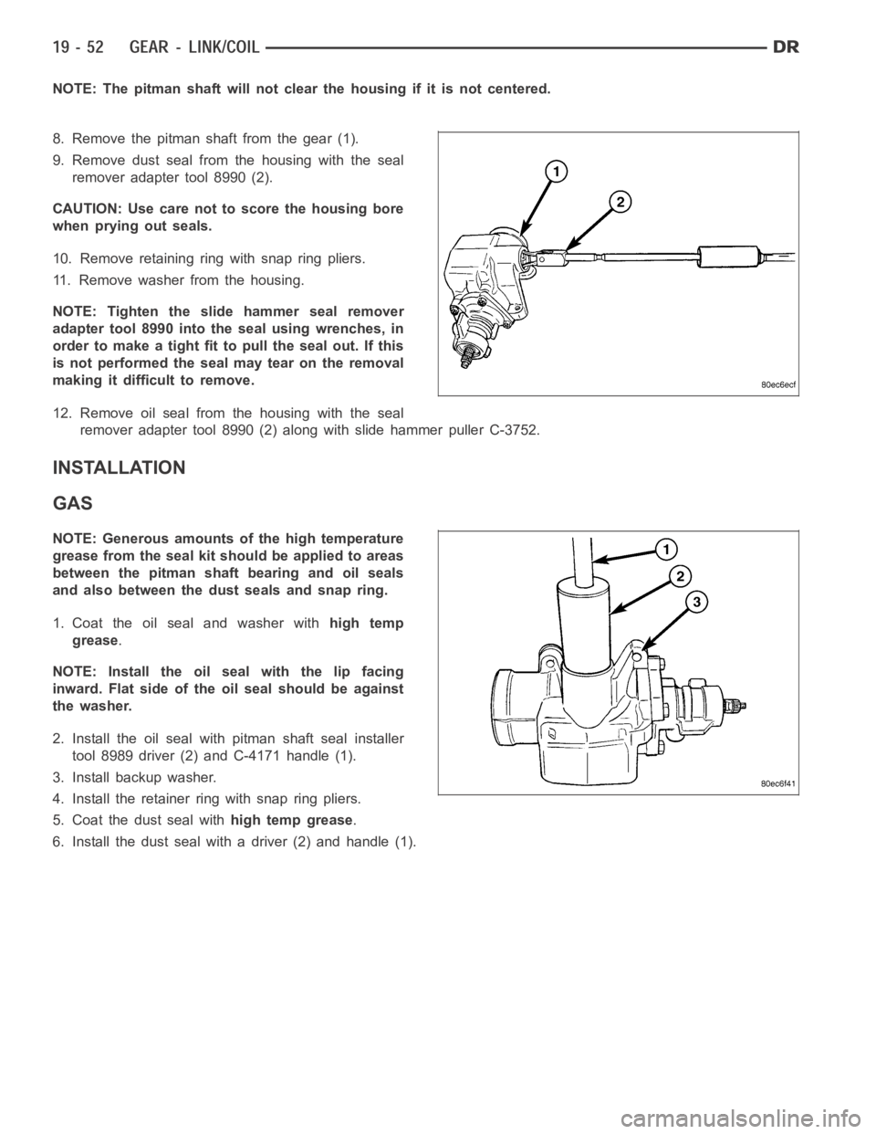
8. Remove the pitman shaft from the gear (1).
9. Remove dust seal from the housing with the seal
remover adapter tool 8990 (2).
CAUTION: Use care not to score the housing bore
when prying out seals.
10. Removeretainingringwithsnapringpliers.
11. Remove washer from the housing.
NOTE: Tighten the slide hammer seal remover
adapter tool 8990 into the seal using wrenches, in
order to make a tight fit to pull the seal out. If this
is not performed the seal may tear on the removal
making it difficult to remove.
12. Remove oil seal from the housing with the seal
remover adapter tool 8990 (2) along with slide hammer puller C-3752.
INSTALLATION
GAS
NOTE: Generous amounts of the high temperature
grease from the seal kit should be applied to areas
between the pitman shaft bearing and oil seals
and also between the dust seals and snap ring.
1. Coat the oil seal and washer withhigh temp
grease.
NOTE: Install the oil seal with the lip facing
inward. Flat side of the oil seal should be against
the washer.
2. Install the oil seal with pitman shaft seal installer
tool 8989 driver (2) and C-4171 handle (1).
3. Install backup washer.
4. Install the retainer ring with snap ring pliers.
5. Coat the dust seal withhigh temp grease.
6. Install the dust seal with a driver (2) and handle (1).
Page 2458 of 5267
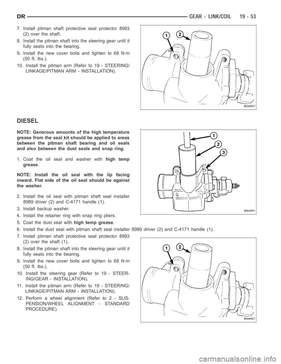
7. Install pitman shaft protective seal protector 8993
(2)overtheshaft.
8. Install the pitman shaft into the steering gear until it
fully seats into the bearing.
9. Install the new cover bolts and tighten to 68 Nꞏm
(50 ft. lbs.).
10. Install the pitman arm (Refer to 19 - STEERING/
LINKAGE/PITMAN ARM - INSTALLATION).
DIESEL
NOTE: Generous amounts of the high temperature
grease from the seal kit should be applied to areas
between the pitman shaft bearing and oil seals
and also between the dust seals and snap ring.
1. Coat the oil seal and washer withhigh temp
grease.
NOTE: Install the oil seal with the lip facing
inward. Flat side of the oil seal should be against
the washer.
2. Install the oil seal with pitman shaft seal installer
8989 driver (2) and C-4171 handle (1).
3. Install backup washer.
4. Install the retainer ring with snap ring pliers.
5. Coat the dust seal withhigh temp grease.
6. Install the dust seal with pitman shaft seal installer 8989 driver (2) andC-4171handle(1).
7. Install pitman shaft protective seal protector 8993
(2)overtheshaft(1).
8. Install the pitman shaft into the steering gear until it
fully seats into the bearing.
9. Install the new cover bolts and tighten to 68 Nꞏm
(50 ft. lbs.).
10. Install the steering gear (Refer to 19 - STEER-
ING/GEAR - INSTALLATION).
11. Install the pitman arm (Refer to 19 - STEERING/
LINKAGE/PITMAN ARM - INSTALLATION).
12. Perform a wheel alignment (Refer to 2 - SUS-
PENSION/WHEEL ALIGNMENT - STANDARD
PROCEDURE).
Page 2463 of 5267
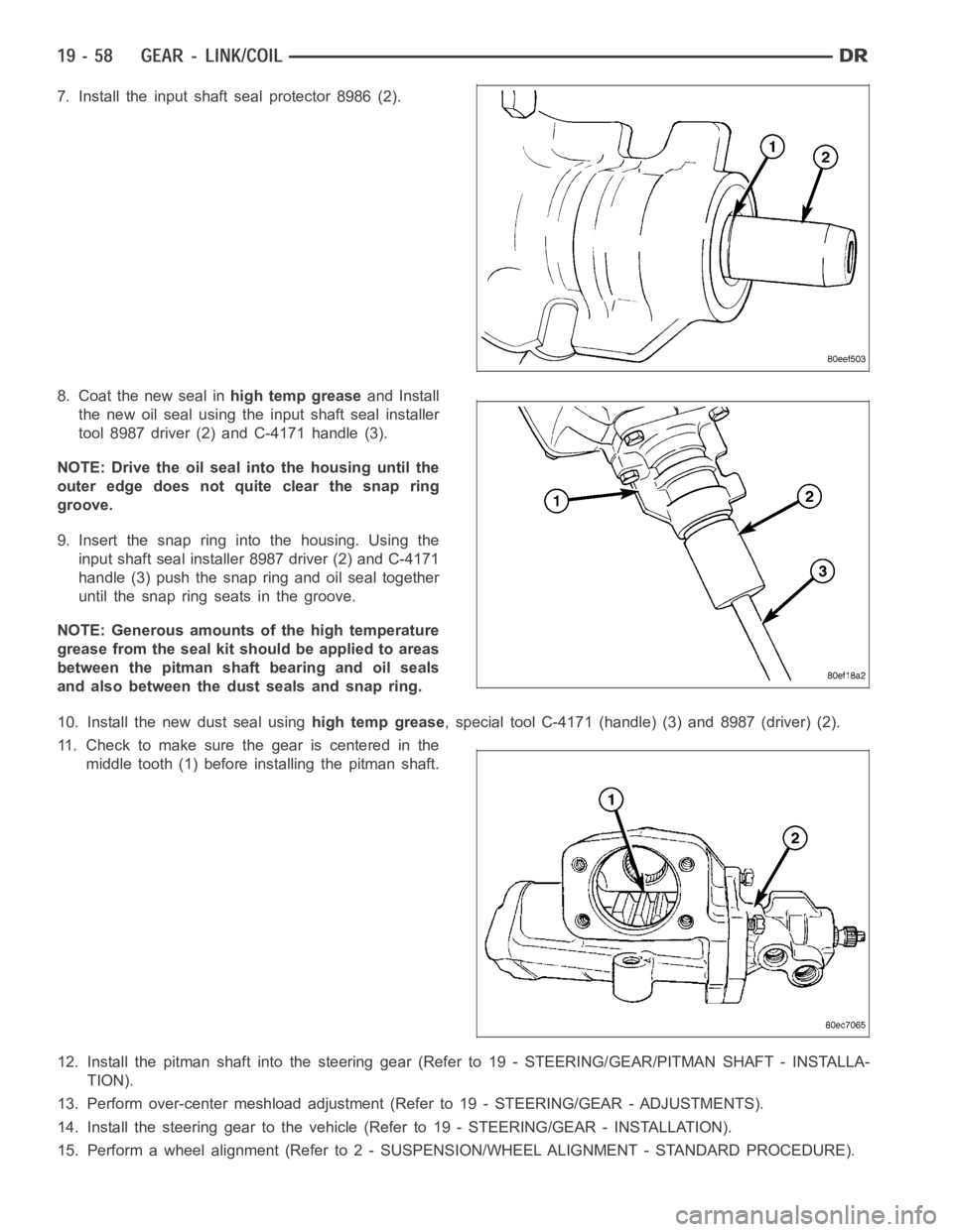
7. Install the input shaft seal protector 8986 (2).
8. Coat the new seal inhigh temp greaseand Install
the new oil seal using the input shaft seal installer
tool 8987 driver (2) and C-4171 handle (3).
NOTE: Drive the oil seal into the housing until the
outer edge does not quite clear the snap ring
groove.
9. Insert the snap ring into the housing. Using the
input shaft seal installer 8987 driver (2) and C-4171
handle (3) push the snap ring and oil seal together
until the snap ring seats in the groove.
NOTE: Generous amounts of the high temperature
grease from the seal kit should be applied to areas
between the pitman shaft bearing and oil seals
and also between the dust seals and snap ring.
10. Install the new dust seal usinghigh temp grease, special tool C-4171 (handle) (3) and 8987 (driver) (2).
11. Check to make sure the gear is centered in the
middle tooth (1) before installing the pitman shaft.
12. Install the pitman shaft into the steering gear (Refer to 19 - STEERING/GEAR/PITMAN SHAFT - INSTALLA-
TION).
13. Perform over-center meshload adjustment (Refer to 19 - STEERING/GEAR- ADJUSTMENTS).
14. Install the steering gear to the vehicle (Refer to 19 - STEERING/GEAR - INSTALLATION).
15. Perform a wheel alignment (Refer to2 - SUSPENSION/WHEEL ALIGNMENT - STANDARD PROCEDURE).
Page 2483 of 5267
1. Raise the front end of the vehicle off the ground until the wheels are freeto turn.
2. Remove the return line from the pump.
NOTE: If vehicle is equipped with a hydraulic booster remove both return lines from the pump.
3. Plug the return line port/ports at the pump.
4. Position the return line/lines into a large container to catch the fluid.
5. While an assistant is filling the pump reservoir start the engine.
6. With the engine running at idle turn the wheel back and forth.
NOTE: Do not contact or hold the wheel against the steering stops.
7. Run a quart of fluid through the system then stop the engine and install the return line/lines.
8. Fill the system with fluid and perform Steering Pump Initial Operation,(Refer to 19 - STEERING/PUMP - STAN-
DARD PROCEDURE).
9. Start the engine and run it for fifteen minutes then stop the engine.
10. Remove the return line/lines from the pump and plug the pump port/ports.
11. Pour fresh fluid into the reservoir and check the draining fluid for contamination. If the fluid is still contaminated,
then flush the system again.
12. Install the return line/lines and perform Steering Pump Initial Operation, (Refer to 19 - STEERING/PUMP -
STANDARD PROCEDURE).
POWER STEERING PUMP - INITIAL OPERATION
WARNING: THE FLUID LEVEL SHOULD BE CHECKED WITH ENGINE OFF TO PREVENT INJURYFROMMOV-
ING COMPONENTS.
CAUTION: MOPAR
ATF+4 is to be used in the power steering system. No other power steering or auto-
matic transmission fluid is to be used in the system. Damage may result to the power steering pump and
system if any other fluid is used, and do not overfill.
Wipe filler cap clean, then check the fluid level. The dipstick should indicateCOLDwhen the fluid is at normal
temperature.
1. Turn steering wheel all the way to the left.
2. Fill reservoir up to FULL HOT level and crank engine until it just starts.(DO NOT TURN STEERING WHEEL).
Then turn vehicle off. And recheck fluid level, to Full COLD.
3. Crank engine again until it just starts, (DO NOT MOVE STEERING WHEEL). and turn vehicle off. Recheck fluid
leveltoFullCOLD.
4. Turn engine on again, (DO NOT MOVE STEERING WHEEL) and let the vehicle idle for 5 minutes. If possible
apply a 20 in-Hg vacuum to the reservoir, while engine is idling.
5. Turn engine off and recheck fluid level, to FULL COLD.
6.If the Steering gear is replacedensure reservoir is at FULL HOT level, start engine and turn wheel to left. Stop
Engine and recheck fluid level to FULL HOT. Start engine and turn wheel to the right. Stop engine and check
fluid level is at FULL COLD.
7. Fill the pump fluid reservoir to the proper level and let the fluid settlefor at least two (2) minutes.
8. Start the engine. With the engine idling maintain the fluid level.
9. Raise the front wheels off the ground.
10. Slowly turn the steering wheel lock-to-lock 20 times with the engine off while checking the fluid level.
NOTE: For vehicles with long return lines or oil coolers turn wheel 40 times.
11. Lower the front wheels and let the engine idle for two minutes.
12. Turn the steering wheel in both direction and verify power assist and quiet operation of the pump.
If the fluid is extremely foamy or milky looking, allow the vehicle to standa few minutes and repeat the procedure.
Page 2487 of 5267
FLUID
DESCRIPTION
NOTE: It is normal that some pressure will build up inside the reservoir, especially, with a warm vehicle. A
slight popping noise upon removal ofthe cap is normal. The fluid level should read between the ADD and
the FULL COLD marks. When the fluid is hotit should read between ADD and FULLHOT marks. Only add
fluid when the vehicle is cold.
The recommended fluid for the power steering system is Mopar
AT F + 4 .
Mopar
ATF+4, when new is red in color. The ATF+4 is dyed red so it can be identified from other fluids used in the
vehicle such as engine oil or antifreeze. The red color is not permanent andis not an indicator of fluid condition, As
the vehicle is driven, the ATF+4 will begin to look darker in color and may eventually become brown.THIS IS NOR-
MAL.ATF+4 also has a unique odor that may change with age. Consequently, odor and color cannot be used to
indicate the fluid condition or the need for a fluid change.
STANDARD PROCEDURE
POWER STEERING FLUID LEVEL CHECKING
WARNING: FLUID LEVEL SHOULD BE CHECKED WITH THE ENGINE OFF TO PREVENT PERSONAL INJURY
FROM MOVING PARTS.
CAUTION: MOPAR
ATF+4 is to be used in the power steering system. No other power steering or auto-
matic transmission fluid is to be used in the system. Damage may result to the power steering pump and
system if any other fluid is used, and do not overfill.
The power steering fluid level can be viewed on the dipstick attached to thefiller cap. There are two ranges listed
on the dipstick, COLD and HOT. Before opening power steering system, wipe the reservoir filler cap free of dirt and
debris. Remove the cap and check the fluid level on its dipstick. When the fluid is at normal ambient temperature,
approximately 21°C to 27°C (70°F to 80°F), the fluid level should read between the minimum and maximum area of
the cold range. When the fluid is hot, fluid level is allowed to read up to thehighest end of the HOT range. Only add
fluid when the vehicle is cold.
Use only Mopar
AT F + 4 .Do not overfill the power steering system.
Page 2732 of 5267
P0218-HIGH TEMPERATURE OPERATION ACTIVATED
For a complete wiring diagramRefer to Section 8W.
When Monitored:
Whenever the engine is running.
Set Condition:
Immediately when a Overheat shift schedule is activated when the Transmission Oil Temperature reaches 155°
C or 240° F.
Possible Causes
ENGINE COOLING SYSTEM OPERATION
TRANSMISSION OIL COOLER PLUGGED
H I G H T E M P E R AT U R E O P E R AT I O N S A C T I VAT E D
Always perform the Pre-Diagnostic Troubleshooting procedure before proceeding. (Refer to 21 - TRANSMIS-
SION/TRANSAXLE/AUTOMATIC - 42RLE - STANDARD PROCEDURE)
Theory of Operation
If the transmission oil temperature rises above 115° C (240° F), the overheat shift schedule is activated refer to
Transmission Operation as a function of Transmission Oil Temperature andthe code is set. The DTC is an infor-
mational code only and is being set to aid the technician in determining root cause of a customer driveability issue.
The code is also intended to alert the technician to determine if a cooling system malfunction has occurred or if an
additional transmission air to oil cooler should be added to the vehicle ifthe customer regularly drives in a manner
that overheats the transmission. Extended operation above 115° C (240° F)will reduce the durability of the trans-
mission and should be avoided. Correcting the cooling system malfunctionor installing an additional transmission oil
cooler will improve transmission durability especially for customers who operate in city/construction stop and go traf-
fic, tow trailers regularly, drive aggressively in low gear or drive regularly in mountainous areas.
Diagnostic Test
1.CHECK ENGINE COOLING SYSTEM
Perform Engine Cooling System diagnostics per the Service Information.
Is the Engine Cooling System functioning properly?
Ye s>>
Go To 2
No>>
Repair the cause of the engine overheating. Refer to the Service Information for the related diagnostic
or repair procedures.
Perform 42RLE TRANSMISSION VERIFICATION TEST - VER 1. (Refer to 21 - TRANSMISSION/
TRANSAXLE/AUTOMATIC - 42RLE - STANDARD PROCEDURE)
2.TRANSMISSION OIL COOLER RESTRICTED
Check the Transmission Oil Cooler Flow in accordance with the Service Information.
Is the transmission oil cooler restricted or plugged?
Ye s>>
Go To 3
No>>
Repair the cause of the plugged Transmission Oil Cooler as necessary and repair or replace the Trans-
mission Oil Cooler per the Service Information.
Perform 42RLE TRANSMISSION VERIFICATION TEST - VER 1. (Refer to 21 - TRANSMISSION/
TRANSAXLE/AUTOMATIC - 42RLE - STANDARD PROCEDURE)
Page 2733 of 5267
3.HIGH TEMPERATURE OPERATION
This DTC is an informational DTC designed to aid the Technician in diagnosing shift quality complaints.
This DTC indicates that the transmission has been operating in the
Overheatshift schedule which may generate
a customer complaint.
The customer driving patterns may indicate the need for an additional transmission oil cooler.
With the scan tool, check the DTC EVENT DATA to help identify the conditionsin which the DTC was set.
Check for any Service Information Tune-ups or Service Bulletins for any possible causes that may apply.
If there are no possible causes remaining, view repair.
Repair
Repair the cause of transmission overheating per the Service Information.
Perform 42RLE TRANSMISSION VERIFICATION TEST - VER 1. (Refer to 21 - TRANSMISSION/
TRANSAXLE/AUTOMATIC - 42RLE - STANDARD PROCEDURE)