2006 DODGE RAM SRT-10 oil temperature
[x] Cancel search: oil temperaturePage 3077 of 5267
SENSOR-TRANSMISSION TEMPERATURE
DESCRIPTION
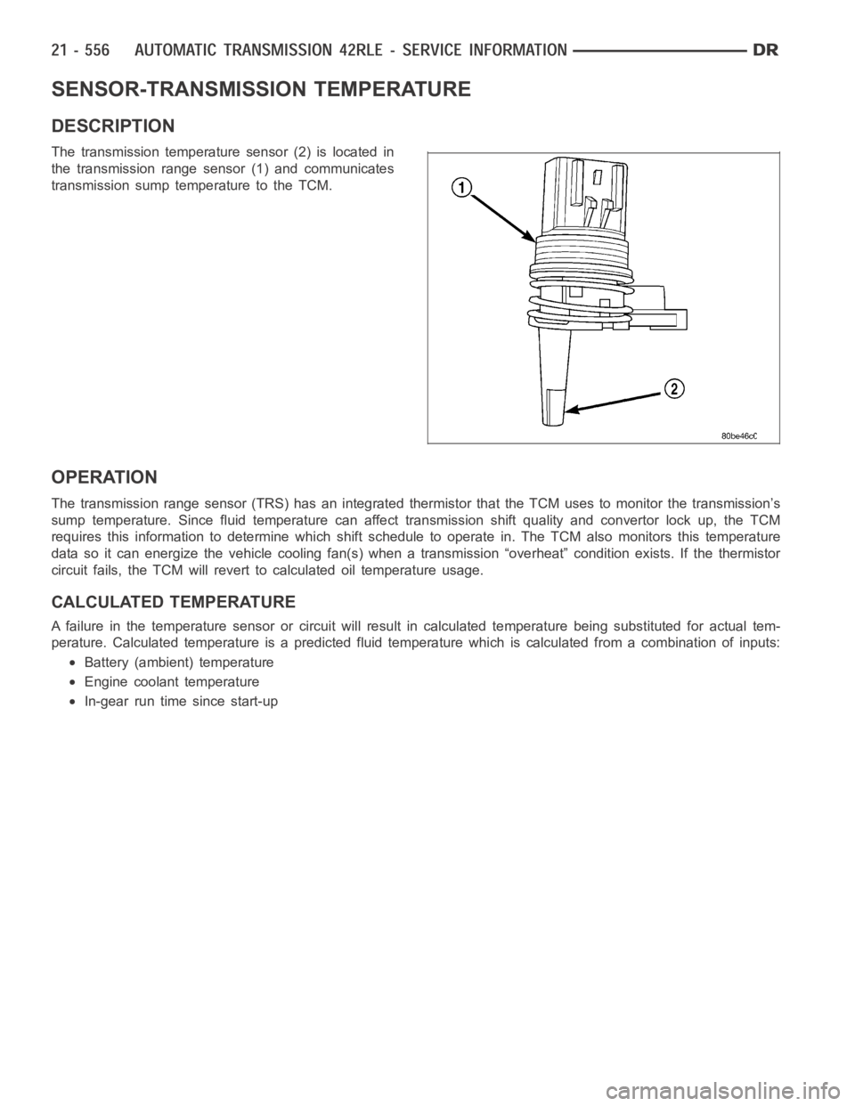
The transmission temperature sensor (2) is located in
the transmission range sensor (1) and communicates
transmission sump temperature to the TCM.
OPERATION
The transmission range sensor (TRS) has an integrated thermistor that theTCM uses to monitor the transmission’s
sump temperature. Since fluid temperature can affect transmission shiftquality and convertor lock up, the TCM
requires this information to determine which shift schedule to operate in. The TCM also monitors this temperature
data so it can energize the vehicle cooling fan(s) when a transmission “overheat” condition exists. If the thermistor
circuit fails, the TCM will revert to calculated oil temperature usage.
CALCULATED TEMPERATURE
A failure in the temperature sensor or circuit will result in calculated temperature being substituted for actual tem-
perature. Calculated temperature is a predicted fluid temperature whichis calculated from a combination of inputs:
Battery (ambient) temperature
Engine coolant temperature
In-gear run time since start-up
Page 3080 of 5267
THERMAL VALVE
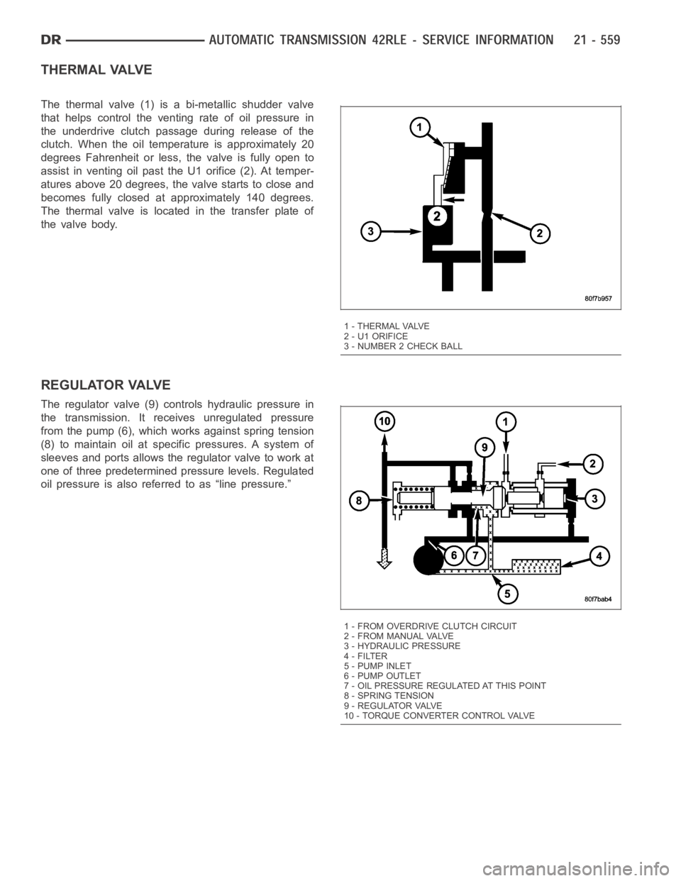
The thermal valve (1) is a bi-metallic shudder valve
that helps control the venting rate of oil pressure in
the underdrive clutch passage during release of the
clutch. When the oil temperature is approximately 20
degrees Fahrenheit or less, the valve is fully open to
assist in venting oil past the U1 orifice (2). At temper-
atures above 20 degrees, the valve starts to close and
becomes fully closed at approximately 140 degrees.
The thermal valve is located in the transfer plate of
the valve body.
REGULATOR VALVE
The regulator valve (9) controls hydraulic pressure in
the transmission. It receives unregulated pressure
from the pump (6), which works against spring tension
(8) to maintain oil at specific pressures. A system of
sleeves and ports allows the regulator valve to work at
one of three predetermined pressure levels. Regulated
oil pressure is also referred to as “line pressure.”
1 - THERMAL VALVE
2 - U1 ORIFICE
3 - NUMBER 2 CHECK BALL
1 - FROM OVERDRIVE CLUTCH CIRCUIT
2 - FROM MANUAL VALVE
3 - HYDRAULIC PRESSURE
4-FILTER
5-PUMPINLET
6 - PUMP OUTLET
7 - OIL PRESSURE REGULATED AT THIS POINT
8 - SPRING TENSION
9 - REGULATOR VALVE
10 - TORQUE CONVERTER CONTROL VALVE
Page 3109 of 5267
P0218-HIGH TEMPERATURE OPERATION ACTIVATED
For a complete wiring diagramRefer to Section 8W.
Theory of Operation
The DTC is intended as an informational DTC to aid the technician in determining the root cause of a customer
dirveability issue. The DTC is also intended to alert the technician to determine if a cooling system malfunction has
occurred or if an additional transmission air to oil cooler is needed to support the customers driving behavior.
When Monitored:
Whenever the engine is running.
Set Condition:
Immediately after a Overheat shift schedule is activated when the Transmission temperature exceeds 127° C
or 260° F.
Possible Causes
H I G H T E M P E R AT U R E O P E R AT I O N A C T I VAT E D
TORQUE CONVERTER CLUTCH SLIPPING / NOT ACTIVATING
EXCESSIVE TIME IDLING IN GEAR
Always perform the Pre-Diagnostic Troubleshooting procedure before proceeding. (Refer to 21 - TRANSMIS-
SION/TRANSAXLE/AUTOMATIC - 45RFE/545RFE - STANDARD PROCEDURE)
Diagnostic Test
1.HIGH TEMPERATURE OPERATION
This DTC is an informational DTC designed to aid the Technician in diagnosing shift quality complaints.
This DTC indicates that the transmission has been operating in the
Overheatshift schedule which may generate
a customer complaint.
The customer driving patterns may indicate the need for an additional transmission oil cooler.
Verify proper Engine cooling system operation which would affect proper transmission operation.
Verify proper torque converter clutch operation.
With the scan tool, check the DTC EVENT DATA to help identify the conditionsin which the DTC was set.
If there are no possible causes remaining, view repair.
Repair
Repair the cause of transmission overheating. Refer to the Service Information for the proper repair
procedure. Make sure to check for any Service Bulletins pertaining to thisproblem.
Perform 45RFE/545RFE TRANSMISSION VERIFICATION TEST - VER 1. (Refer to 21- TRANSMIS-
SION/TRANSAXLE/AUTOMATIC - 45RFE/545RFE - STANDARD PROCEDURE)
Page 3150 of 5267
Diagnostic Test
1.CHECKFORRELATEDDTCS
With the scan tool, check for other transmission DTCs.
If any of these DTCs are present, perform their respective tests first.
Are there any Transmission; solenoid, line pressure, speed sensor, and/or loss of prime DTC’s present?
Ye s>>
Refer to the Transmission category and perform the appropriate symptom. If any of these DTCs are
present, they may cause a Speed Ratio Error. Perform the test for P0944 firstifitispresent.
No>>
Go To 2
2.CHECK IF DTC P0731 IS CURRENT
With the scan tool, perform the 1st Gear Clutch Test. Follow the instructions on the scan tool.
Increase the throttle angle or TPS Degree to 30° for no more than a few seconds.
CAUTION: Do not overheat the transmission.
Did the Clutch Test pass, Input Speed remain at zero?
Ye s>>
Go To 3
No>>
Go To 4
3.CHECK FOR INTERMITTENT OPERATION
The conditions to set this DTC are not currently present.
With the scan tool, check the DTC EVENT DATA to help identify the conditionsin which the DTC was set.
If the DTC Event Data shows fault P0731 was set in Park, Reverse, or Neutral,replace the Powertrain Control
Module.
If the DTC Event Data shows fault P0731 set with input RPM = zero, check the input speed sensor and related
wiring.
If the DTC Event Data shows fault P0731 set with line pressure significantly below desired line pressure, check
for the cause of low line pressure (i.e., oil level, mis-installed or damaged primary filter or filter seal, sticking
main regulator valve in pump, etc.).
If the DTC Event Data shows fault P0731 set with the UD pressure switch open (but line pressure matches
Desired Line Pressure), air check the UD hydraulic clutch circuit for leakage per the Service Information. If the
UD hydraulic clutch circuit is OK, replace the solenoid/TRS assembly.
Check the gearshift linkage adjustment.
Intermittent Gear Ratio DTCs can be set by problems in the Input and Output Speed Sensor circuits and/or Speed
Sensor Ground circuit.
Remove the Ignition Switch Feed fuse from the TIPM.
CAUTION: Removal of the Ignition Switch Feed fuse from the TIPM will prevent the vehicle from being
startedingear.
WARNING: The Ignition Switch Feed fuse must be removed from the TIPM. Failure to do so can result in
personal injury or death.
Install the Transmission Simulator, Miller tool #8333.
Wiggle wiring and connectors while checking for intermittent operation with the Transmission Simulator.
Gear ratio DTCs can also be set under extreme temperature conditions.
Verify if the problem is only experienced under extreme hot or cold conditions.
Were there any problems found.
Ye s>>
Repair as necessary.
Perform 45RFE/545RFE TRANSMISSION VERIFICATION TEST - VER 1. (Refer to 21- TRANSMIS-
SION/TRANSAXLE/AUTOMATIC - 45RFE/545RFE - STANDARD PROCEDURE)
No>>
Te s t C o m p l e t e .
Page 3157 of 5267
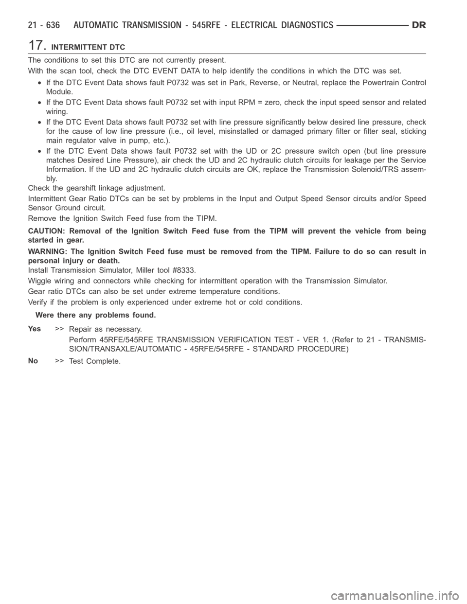
17.INTERMITTENT DTC
The conditions to set this DTC are not currently present.
With the scan tool, check the DTC EVENT DATA to help identify the conditionsin which the DTC was set.
If the DTC Event Data shows fault P0732 was set in Park, Reverse, or Neutral,replace the Powertrain Control
Module.
If the DTC Event Data shows fault P0732 set with input RPM = zero, check the input speed sensor and related
wiring.
If the DTC Event Data shows fault P0732 set with line pressure significantly below desired line pressure, check
for the cause of low line pressure (i.e., oil level, misinstalled or damaged primary filter or filter seal, sticking
main regulator valve in pump, etc.).
If the DTC Event Data shows fault P0732 set with the UD or 2C pressure switch open (but line pressure
matches Desired Line Pressure), air check the UD and 2C hydraulic clutch circuits for leakage per the Service
Information. If the UD and 2C hydraulic clutch circuits are OK, replace theTransmission Solenoid/TRS assem-
bly.
Check the gearshift linkage adjustment.
Intermittent Gear Ratio DTCs can be set by problems in the Input and Output Speed Sensor circuits and/or Speed
Sensor Ground circuit.
Remove the Ignition Switch Feed fuse from the TIPM.
CAUTION: Removal of the Ignition Switch Feed fuse from the TIPM will prevent the vehicle from being
startedingear.
WARNING: The Ignition Switch Feed fuse must be removed from the TIPM. Failure to do so can result in
personal injury or death.
Install Transmission Simulator, Miller tool #8333.
Wiggle wiring and connectors while checking for intermittent operation with the Transmission Simulator.
Gear ratio DTCs can also be set under extreme temperature conditions.
Verify if the problem is only experienced under extreme hot or cold conditions.
Were there any problems found.
Ye s>>
Repair as necessary.
Perform 45RFE/545RFE TRANSMISSION VERIFICATION TEST - VER 1. (Refer to 21- TRANSMIS-
SION/TRANSAXLE/AUTOMATIC - 45RFE/545RFE - STANDARD PROCEDURE)
No>>
Te s t C o m p l e t e .
Page 3163 of 5267

18.CHECK FOR INTERMITTENT OPERATION
The conditions to set this DTC are not currently present.
With the scan tool, check the DTC EVENT DATA to help identify the conditionsin which the DTC was set.
If the DTC Event Data shows fault P0733 was set in the Park, Reverse, or Neutral, replace the Powertrain
Control Module.
If the DTC Event Data shows fault P0733 set with input RPM = zero, check the input speed sensor and related
wiring.
If the DTC Event Data shows fault P0733 set with line pressure significantly below desired line pressure, check
for the cause of low line pressure (i.e., oil level, misinstalled or damaged primary filter or filter seal, sticking
main regulator valve in pump, etc.).
If the DTC Event Data shows fault P0733 set with the OD or UD pressure switch open (but line pressure
matches Desired Line Pressure), air check the OD and UD hydraulic clutch circuits for leakage per the Service
Information. If the OD and UD hydraulic clutch circuits are OK, replace theTransmission Solenoid/TRS assem-
bly.
Check the gearshift linkage adjustment.
Intermittent Gear Ratio DTCs can be set by problems in the Input and Output Speed Sensor circuits and/or Speed
Sensor Ground circuit.
Remove the Ignition Switch Feed fuse from the TIPM.
CAUTION: Removal of the Ignition Switch Feed fuse from the TIPM will prevent the vehicle from being
startedingear.
WARNING: The Ignition Switch Feed fuse must be removed from the TIPM. Failure to do so can result in
personal injury or death.
Install the Transmission Simulator, Miller tool #8333.
Wiggle wiring and connectors while checking for intermittent operation with the Transmission Simulator.
Gear ratio DTCs can also be set under extreme temperature conditions.
Verify if the problem is only experienced under extreme hot or cold conditions.
Were there any problems found.
Ye s>>
Repair as necessary.
Perform 45RFE/545RFE TRANSMISSION VERIFICATION TEST - VER 1. (Refer to 21- TRANSMIS-
SION/TRANSAXLE/AUTOMATIC - 45RFE/545RFE - STANDARD PROCEDURE)
No>>
Te s t C o m p l e t e .
Page 3197 of 5267
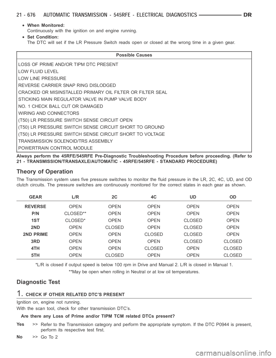
When Monitored:
Continuously with the ignition on and engine running.
Set Condition:
The DTC will set if the LR Pressure Switch reads open or closed at the wrong time in a given gear.
Possible Causes
LOSS OF PRIME AND/OR TIPM DTC PRESENT
LOW FLUID LEVEL
LOW LINE PRESSURE
REVERSE CARRIER SNAP RING DISLODGED
CRACKED OR MISINSTALLED PRIMARY OIL FILTER OR FILTER SEAL
STICKING MAIN REGULATOR VALVE IN PUMP VALVE BODY
NO. 1 CHECK BALL CUT OR DAMAGED
WIRING AND CONNECTORS
(T50) LR PRESSURE SWITCH SENSE CIRCUIT OPEN
(T50) LR PRESSURE SWITCH SENSE CIRCUIT SHORT TO GROUND
(T50) LR PRESSURE SWITCH SENSE CIRCUIT SHORT TO VOLTAGE
TRANSMISSION SOLENOID/TRS ASSEMBLY
POWERTRAIN CONTROL MODULE
Always perform the 45RFE/545RFE Pre-Diagnostic Troubleshooting Procedure before proceeding. (Refer to
21 - TRANSMISSION/TRANSAXLE/AUTOMATIC - 45RFE/545RFE - STANDARD PROCEDURE)
Theory of Operation
The Transmission system uses five pressure switches to monitor the fluid pressure in the LR, 2C, 4C, UD, and OD
clutch circuits. The pressure switches are continuously monitored for the correct states in each gear as shown.
GEAR L/R 2C 4C UD OD
REVERSEOPEN OPEN OPEN OPEN OPEN
P/NCLOSED** OPEN OPEN OPEN OPEN
1STCLOSED* OPEN OPEN CLOSED OPEN
2NDOPEN CLOSED OPEN CLOSED OPEN
2ND PRIMEOPEN OPEN CLOSED CLOSED OPEN
3RDOPEN OPEN OPEN CLOSED CLOSED
4THOPEN OPEN CLOSED OPEN CLOSED
5THOPEN CLOSED OPEN OPEN CLOSED
*L/R is closed if output speed is below 100 rpm in Drive and Manual 2. L/R is closed in Manual 1.
**May be open when rolling in Neutral or at low oil temperatures.
Diagnostic Test
1.CHECK IF OTHER RELATED DTC’S PRESENT
Ignition on, engine not running.
With the scan tool, check for other transmission DTC’s.
Are there any Loss of Prime and/or TIPM TCM related DTCs present?
Ye s>>
Refer to the Transmission category and perform the appropriate symptom. If the DTC P0944 is present,
perform its respective test first.
No>>
Go To 2
Page 3212 of 5267
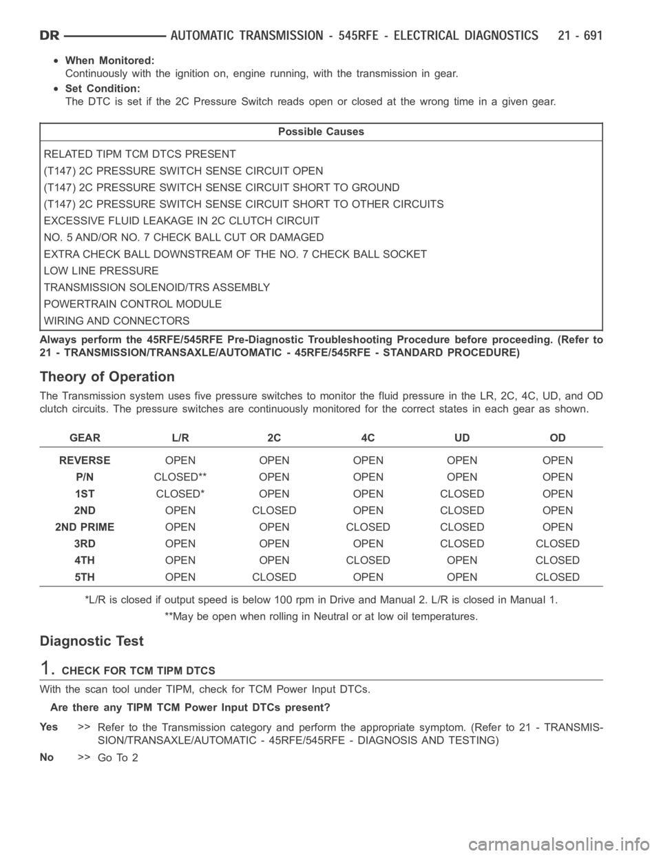
When Monitored:
Continuously with the ignition on, engine running, with the transmissionin gear.
Set Condition:
The DTC is set if the 2C Pressure Switchreadsopenorclosedatthewrongtimein a given gear.
Possible Causes
RELATED TIPM TCM DTCS PRESENT
(T147) 2C PRESSURE SWITCH SENSE CIRCUIT OPEN
(T147) 2C PRESSURE SWITCH SENSE CIRCUIT SHORT TO GROUND
(T147) 2C PRESSURE SWITCH SENSE CIRCUIT SHORT TO OTHER CIRCUITS
EXCESSIVE FLUID LEAKAGE IN 2C CLUTCH CIRCUIT
NO. 5 AND/OR NO. 7 CHECK BALL CUT OR DAMAGED
EXTRA CHECK BALL DOWNSTREAM OF THE NO. 7 CHECK BALL SOCKET
LOW LINE PRESSURE
TRANSMISSION SOLENOID/TRS ASSEMBLY
POWERTRAIN CONTROL MODULE
WIRING AND CONNECTORS
Always perform the 45RFE/545RFE Pre-Diagnostic Troubleshooting Procedure before proceeding. (Refer to
21 - TRANSMISSION/TRANSAXLE/AUTOMATIC - 45RFE/545RFE - STANDARD PROCEDURE)
Theory of Operation
The Transmission system uses five pressure switches to monitor the fluid pressure in the LR, 2C, 4C, UD, and OD
clutch circuits. The pressure switches are continuously monitored for the correct states in each gear as shown.
GEAR L/R 2C 4C UD OD
REVERSEOPEN OPEN OPEN OPEN OPEN
P/NCLOSED** OPEN OPEN OPEN OPEN
1STCLOSED* OPEN OPEN CLOSED OPEN
2NDOPEN CLOSED OPEN CLOSED OPEN
2ND PRIMEOPEN OPEN CLOSED CLOSED OPEN
3RDOPEN OPEN OPEN CLOSED CLOSED
4THOPEN OPEN CLOSED OPEN CLOSED
5THOPEN CLOSED OPEN OPEN CLOSED
*L/R is closed if output speed is below 100 rpm in Drive and Manual 2. L/R is closed in Manual 1.
**May be open when rolling in Neutral or at low oil temperatures.
Diagnostic Test
1.CHECK FOR TCM TIPM DTCS
With the scan tool under TIPM, check for TCM Power Input DTCs.
Are there any TIPM TCM Power Input DTCs present?
Ye s>>
Refer to the Transmission category and perform the appropriate symptom. (Refer to 21 - TRANSMIS-
SION/TRANSAXLE/AUTOMATIC - 45RFE/545RFE - DIAGNOSIS AND TESTING)
No>>
Go To 2