2006 DODGE RAM SRT-10 sensor
[x] Cancel search: sensorPage 5113 of 5267
ASSEMBLY
HVAC HOUSING
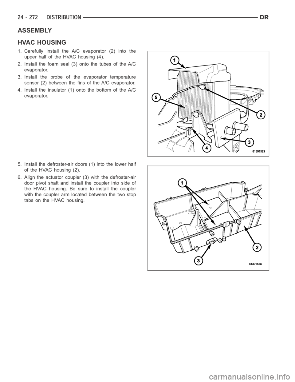
1. Carefully install the A/C evaporator (2) into the
upper half of the HVAC housing (4).
2. Install the foam seal (3) onto the tubes of the A/C
evaporator.
3. Install the probe of the evaporator temperature
sensor (2) between the fins of the A/C evaporator.
4. Install the insulator (1) onto the bottom of the A/C
evaporator.
5. Install the defroster-air doors (1) into the lower half
of the HVAC housing (2).
6. Align the actuator coupler (3) with the defroster-air
door pivot shaft and install the coupler into side of
the HVAC housing. Be sure to install the coupler
with the coupler arm located between the two stop
tabs on the HVAC housing.
Page 5114 of 5267

7. Install the blend-air doors (1) into each of the two
blend door plates (2).
8. Align the actuator coupler (3) with each blend-air
door pivot shaft and install the coupler into side of
each blend door plate. Be sure to install each cou-
pler with the coupler arm located between the two
stop tabs on each blend door plate.
9. Position the lower blend door assembly (2) into the
lower half of the HVAC housing (3) and fully
engage the three retaining tabs (1).
10. Position the upper blend door assembly into the
upper half of the HVAC housing and fully engage
the three retaining tabs.
NOTE: Route the wire lead for the evaporator tem-
perature sensor into the opening located on the
upper half of the HVAC housing prior to installing
the lower half of the HVAC housing.
11. Position the two halves of the HVAC housing
together (3).
12. Install the fifteen screws (6) that secure the two
housing halves together. Tighten the screws to 2.2
Nꞏm (20 in. lbs.).
13. Install the foam seal (4) onto the evaporator con-
densate drain tube (5).
14. Connect the linkage rod (1) to the two blend-air
door levers (2) located on the back of the HVAC
housing.
Page 5117 of 5267
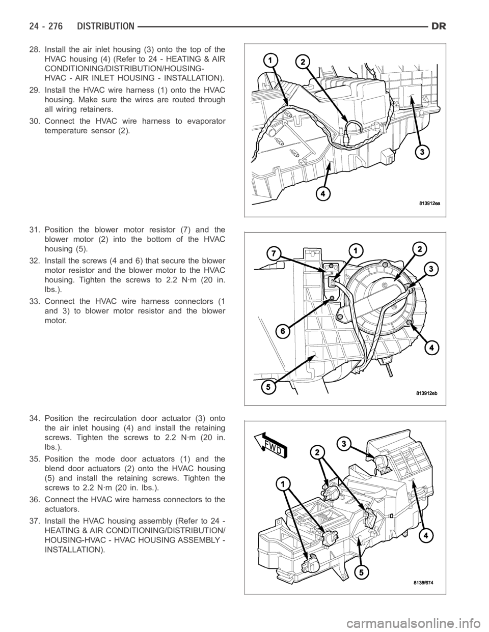
28. Install the air inlet housing (3) onto the top of the
HVAC housing (4) (Refer to 24 - HEATING & AIR
CONDITIONING/DISTRIBUTION/HOUSING-
HVAC - AIR INLET HOUSING - INSTALLATION).
29. Install the HVAC wire harness (1) onto the HVAC
housing. Make sure the wires are routed through
all wiring retainers.
30. Connect the HVAC wire harness to evaporator
temperature sensor (2).
31. Position the blower motor resistor (7) and the
blower motor (2) into the bottom of the HVAC
housing (5).
32. Install the screws (4 and 6) that secure the blower
motor resistor and the blower motor to the HVAC
housing. Tighten the screws to 2.2 Nꞏm (20 in.
lbs.).
33. Connect the HVAC wire harness connectors (1
and 3) to blower motor resistor and the blower
motor.
34. Position the recirculation door actuator (3) onto
the air inlet housing (4) and install the retaining
screws. Tighten the screws to 2.2 Nꞏm (20 in.
lbs.).
35. Position the mode door actuators (1) and the
blend door actuators (2) onto the HVAC housing
(5) and install the retaining screws. Tighten the
screws to 2.2 Nꞏm (20 in. lbs.).
36. Connect the HVAC wire harness connectors to the
actuators.
37. Install the HVAC housing assembly (Refer to 24 -
HEATING & AIR CONDITIONING/DISTRIBUTION/
HOUSING-HVAC - HVAC HOUSING ASSEMBLY -
INSTALLATION).
Page 5118 of 5267

AIR INLET HOUSING
NOTE: The air inlet housing must be removed from HVAC housing and disassembled for service of the
recirculation-air door.
NOTE: If the seals on the air door is deformed or
damaged, the air door must be replaced.
1. Position the recirculation-air door (1) into the air
inlet housing (2).
CAUTION: Make sure that the recirculation-air
door pivot shaft is properly seated in the pivot
seat located in the air inlet housing.
2. Align the actuator coupler (3) with the recirculation-
air door pivot shaft and install the coupler until the
coupler retaining tabs are fully engaged to the air
inlet housing. Be sure to install the coupler with the
coupler arm located between the two stop tabs on
the air inlet housing.
3. Install the two foam insulators (2) into the air inlet
housing (1).
4. Install the air inlet housing onto the HVAC housing
(Refer to 24 - HEATING & AIR CONDITIONING/
DISTRIBUTION/HOUSING-HVAC - AIR INLET
HOUSING - INSTALLATION).
INSTALLATION
HVAC HOUSING ASSEMBLY
NOTE: The HVAC housing must be removedfrom the vehicle and disassembled for service of the A/C evap-
orator, evaporator temperature sensor, mode-air and blend-air doors.
Page 5158 of 5267
EVAPORATOR-A/C
DESCRIPTION
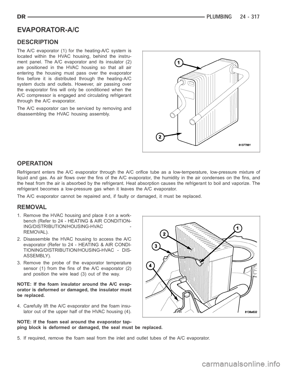
The A/C evaporator (1) for the heating-A/C system is
located within the HVAC housing, behind the instru-
ment panel. The A/C evaporator and its insulator (2)
are positioned in the HVAC housing so that all air
entering the housing must pass over the evaporator
fins before it is distributed through the heating-A/C
system ducts and outlets. However, air passing over
the evaporator fins will only be conditioned when the
A/C compressor is engaged and circulating refrigerant
through the A/C evaporator.
The A/C evaporator can be serviced by removing and
disassembling the HVAC housing assembly.
OPERATION
Refrigerant enters the A/C evaporator through the A/C orifice tube as a low-temperature, low-pressure mixture of
liquid and gas. As air flows over the fins of the A/C evaporator, the humidity in the air condenses on the fins, and
the heat from the air is absorbed by the refrigerant. Heat absorption causes the refrigerant to boil and vaporize. The
refrigerant becomes a low-pressure gas when it leaves the A/C evaporator.
The A/C evaporator cannot be repaired and, if faulty or damaged, it must be replaced.
REMOVAL
1. RemovetheHVAChousingandplaceitonawork-
bench (Refer to 24 - HEATING & AIR CONDITION-
ING/DISTRIBUTION/HOUSING-HVAC -
REMOVAL).
2. Disassemble the HVAC housing to access the A/C
evaporator (Refer to 24 - HEATING & AIR CONDI-
TIONING/DISTRIBUTION/HOUSING-HVAC - DIS-
ASSEMBLY).
3. Remove the probe of the evaporator temperature
sensor (1) from the fins of the A/C evaporator (2)
and position the wire lead (3) out of the way.
NOTE: If the foam insulator around the A/C evap-
orator is deformed or damaged, the insulator must
be replaced.
4. Carefully lift the A/C evaporator and the foam insu-
lator out of the upper half of the HVAC housing (4).
NOTE: If the foam seal around the evaporator tap-
ping block is deformed or damaged, the seal must be replaced.
5. If required, remove the foam seal from the inlet and outlet tubes of the A/Cevaporator.
Page 5159 of 5267
INSTALLATION
NOTE: If the A/C evaporator is being replaced, add 60 milliliters (2 fluid ounces) of refrigerant oil to the
refrigerant system. Use only refrigerant oil of the type recommended for the A/C compressor in the vehicle.
NOTE: Make sure that the foam insulator is prop-
erly positioned in the HVAC housing.
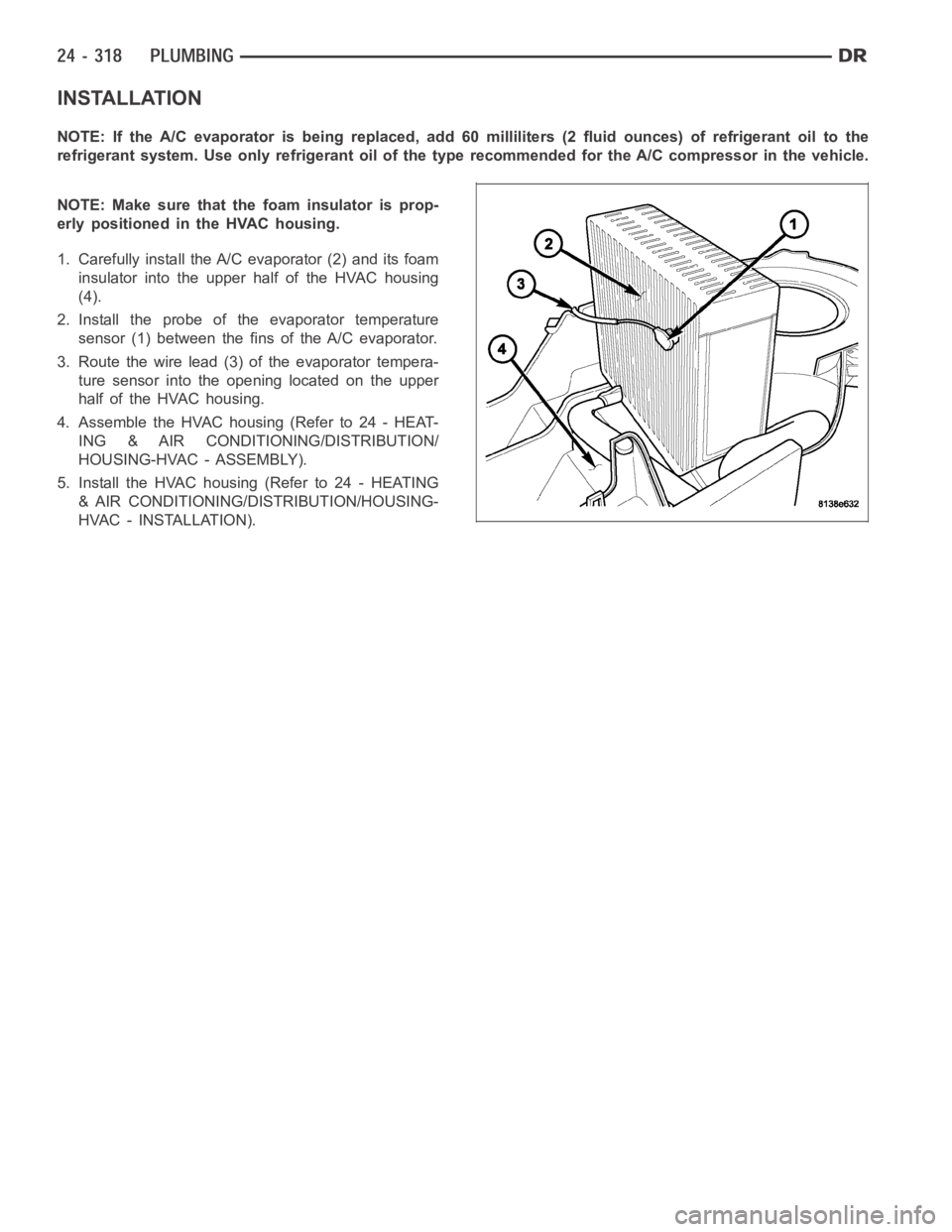
1. Carefully install the A/C evaporator (2) and its foam
insulator into the upper half of the HVAC housing
(4).
2. Install the probe of the evaporator temperature
sensor (1) between the fins of the A/C evaporator.
3. Route the wire lead (3) of the evaporator tempera-
ture sensor into the opening located on the upper
half of the HVAC housing.
4. Assemble the HVAC housing (Refer to 24 - HEAT-
ING & AIR CONDITIONING/DISTRIBUTION/
HOUSING-HVAC - ASSEMBLY).
5. Install the HVAC housing (Refer to 24 - HEATING
& AIR CONDITIONING/DISTRIBUTION/HOUSING-
HVAC - INSTALLATION).
Page 5193 of 5267
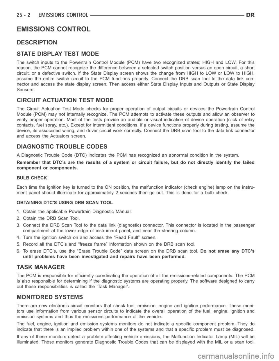
EMISSIONS CONTROL
DESCRIPTION
STATE DISPLAY TEST MODE
The switch inputs to the Powertrain Control Module (PCM) have two recognized states; HIGH and LOW. For this
reason, the PCM cannot recognize the difference between a selected switchposition versus an open circuit, a short
circuit, or a defective switch. If the State Display screen shows the changefromHIGHtoLOWorLOWtoHIGH,
assume the entire switch circuit to the PCM functions properly. Connect the DRB scan tool to the data link con-
nector and access the state display screen. Then access either State Display Inputs and Outputs or State Display
Sensors.
CIRCUIT ACTUATION TEST MODE
The Circuit Actuation Test Mode checks for proper operation of output circuits or devices the Powertrain Control
Module (PCM) may not internally recognize. The PCM attempts to activate these outputs and allow an observer to
verify proper operation. Most of the tests provide an audible or visual indication of device operation (click of relay
contacts, fuel spray, etc.). Except for intermittent conditions, if a device functions properly during testing, assume the
device, its associated wiring, and driver circuit work correctly. Connect the DRB scan tool to the data link connector
and access the Actuators screen.
DIAGNOSTIC TROUBLE CODES
A Diagnostic Trouble Code (DTC) indicates the PCM has recognized an abnormal condition in the system.
Remember that DTC’s are the results of a system or circuit failure, but do not directly identify the failed
component or components.
BULB CHECK
Each time the ignition key is turned to the ON position, the malfunction indicator (check engine) lamp on the instru-
ment panel should illuminate for approximately 2 seconds then go out. Thisis done for a bulb check.
OBTAINING DTC’S USING DRB SCAN TOOL
1. Obtain the applicable Powertrain Diagnostic Manual.
2. Obtain the DRB Scan Tool.
3. Connect the DRB Scan Tool to the data link (diagnostic) connector. This connector is located in the passenger
compartment at the lower edge of instrument panel, and near the steering column.
4. Turn the ignition switch on and access the “Read Fault” screen.
5. Record all the DTC’s and “freeze frame” information shown on the DRB scantool.
6. To erase DTC’s, use the “Erase Trouble Code” data screen on the DRB scan tool.Do not erase any DTC’s
until problems have been investigated and repairs have been performed.
TA S K M A N A G E R
The PCM is responsible for efficiently coordinating the operation of all the emissions-related components. The PCM
is also responsible for determining if the diagnostic systems are operating properly. The software designed to carry
out these responsibilities is called the ’Task Manager’.
MONITORED SYSTEMS
There are new electronic circuit monitors that check fuel, emission, engine and ignition performance. These moni-
tors use information from various sensor circuits to indicate the overalloperation of the fuel, engine, ignition and
emission systems and thus the emissions performance of the vehicle.
The fuel, engine, ignition and emission systems monitors do not indicate aspecific component problem. They do
indicate that there is an implied problem within one of the systems and thata specific problem must be diagnosed.
If any of these monitors detect a problem affecting vehicle emissions, theMalfunction Indicator Lamp (MIL) will be
illuminated. These monitors generate Diagnostic Trouble Codes that can be displayed with the MIL or a scan tool.
Page 5194 of 5267
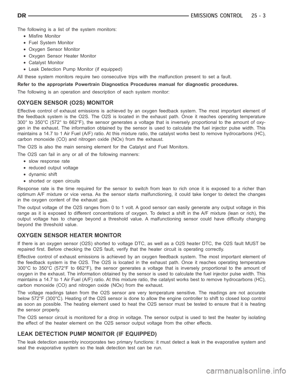
The following is a list of the system monitors:
Misfire Monitor
Fuel System Monitor
Oxygen Sensor Monitor
Oxygen Sensor Heater Monitor
Catalyst Monitor
Leak Detection Pump Monitor (if equipped)
All these system monitors require two consecutive trips with the malfunction present to set a fault.
Refer to the appropriate Powertrain Diagnostics Procedures manual for diagnostic procedures.
The following is an operation and description of each system monitor:
OXYGEN SENSOR (O2S) MONITOR
Effective control of exhaust emissions is achieved by an oxygen feedback system. The most important element of
the feedback system is the O2S. The O2S is located in the exhaust path. Once it reaches operating temperature
300° to 350°C (572° to 662°F), the sensor generates a voltage that is inversely proportional to the amount of oxy-
gen in the exhaust. The information obtained by the sensor is used to calculate the fuel injector pulse width. This
maintains a 14.7 to 1 Air Fuel (A/F) ratio. At this mixture ratio, the catalyst works best to remove hydrocarbons (HC),
carbon monoxide (CO) and nitrogen oxide (NOx) from the exhaust.
The O2S is also the main sensing element for the Catalyst and Fuel Monitors.
The O2S can fail in any or all of the following manners:
slow response rate
reduced output voltage
dynamic shift
shortedoropencircuits
Response rate is the time required for the sensor to switch from lean to richonce it is exposed to a richer than
optimum A/F mixture or vice versa. As the sensor starts malfunctioning, itcould take longer to detect the changes
in the oxygen content of the exhaust gas.
The output voltage of the O2S ranges from 0 to 1 volt. A good sensor can easilygenerate any output voltage in this
range as it is exposed to different concentrations of oxygen. To detect a shift in the A/F mixture (lean or rich), the
output voltage has to change beyond a threshold value. A malfunctioning sensor could have difficulty changing
beyond the threshold value.
OXYGEN SENSOR HEATER MONITOR
If there is an oxygen sensor (O2S) shorted to voltage DTC, as well as a O2S heater DTC, the O2S fault MUST be
repaired first. Before checking the O2S fault, verify that the heater circuit is operating correctly.
Effective control of exhaust emissions is achieved by an oxygen feedback system. The most important element of
the feedback system is the O2S. The O2S is located in the exhaust path. Once it reaches operating temperature
300°C to 350°C (572°F to 662°F), the sensor generates a voltage that is inversely proportional to the amount of
oxygen in the exhaust. The information obtained by the sensor is used to calculate the fuel injector pulse width. This
maintains a 14.7 to 1 Air Fuel (A/F) ratio. At this mixture ratio, the catalyst works best to remove hydrocarbons (HC),
carbon monoxide (CO) and nitrogen oxide (NOx) from the exhaust.
The voltage readings taken from the O2S sensor are very temperature sensitive. The readings are not accurate
below 572°F (300°C). Heating of the O2S sensor is done to allow the engine controllertoshifttoclosedloopcontrol
as soon as possible. The heating element used to heat the O2S sensor must be testedtoensurethatitisheating
the sensor properly.
The O2S sensor circuit is monitored for a drop in voltage. The sensor outputis used to test the heater by isolating
the effect of the heater element on the O2S sensor output voltage from the other effects.
LEAK DETECTION PUMP MONITOR (IF EQUIPPED)
The leak detection assembly incorporates two primary functions: it must detect a leak in the evaporative system and
seal the evaporative system so the leak detection test can be run.