2006 DODGE RAM SRT-10 sensor
[x] Cancel search: sensorPage 5090 of 5267
REMOVAL
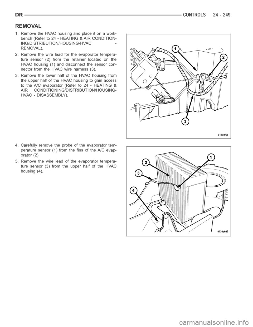
1. RemovetheHVAChousingandplaceitonawork-
bench (Refer to 24 - HEATING & AIR CONDITION-
ING/DISTRIBUTION/HOUSING-HVAC -
REMOVAL).
2. Remove the wire lead for the evaporator tempera-
ture sensor (2) from the retainer located on the
HVAC housing (1) and disconnect the sensor con-
nector from the HVAC wire harness (3).
3. Remove the lower half of the HVAC housing from
the upper half of the HVAC housing to gain access
to the A/C evaporator (Refer to 24 - HEATING &
AIR CONDITIONING/DISTRIBUTION/HOUSING-
HVAC - DISASSEMBLY).
4. Carefully remove the probe of the evaporator tem-
perature sensor (1) from the fins of the A/C evap-
orator (2).
5. Remove the wire lead of the evaporator tempera-
ture sensor (3) from the upper half of the HVAC
housing (4).
Page 5091 of 5267
INSTALLATION
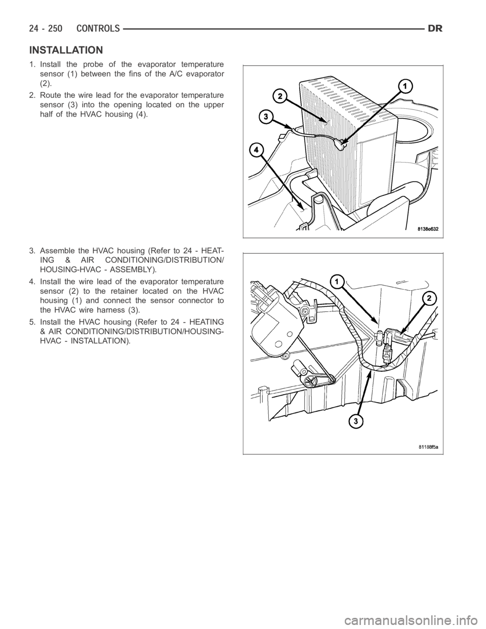
1. Install the probe of the evaporator temperature
sensor (1) between the fins of the A/C evaporator
(2).
2. Route the wire lead for the evaporator temperature
sensor (3) into the opening located on the upper
half of the HVAC housing (4).
3. Assemble the HVAC housing (Refer to 24 - HEAT-
ING & AIR CONDITIONING/DISTRIBUTION/
HOUSING-HVAC - ASSEMBLY).
4. Install the wire lead of the evaporator temperature
sensor (2) to the retainer located on the HVAC
housing (1) and connect the sensor connector to
theHVACwireharness(3).
5. Install the HVAC housing (Refer to 24 - HEATING
& AIR CONDITIONING/DISTRIBUTION/HOUSING-
HVAC - INSTALLATION).
Page 5092 of 5267

TRANSDUCER-A/C PRESSURE
DESCRIPTION
The A/C pressure transducer (1) is a switch that is
installed on a fitting located on the A/C discharge line.
An internally threaded fitting on the A/C pressure
transducer connects it to the externally threaded
Schrader-type fitting on the A/C discharge line. A rub-
ber O-ring seals the connection between the A/C pres-
sure transducer and the discharge line fitting. The A/C
pressure transducer is connected to the vehicle elec-
trical system by a molded plastic connector with three
terminals.
OPERATION
The A/C pressure transducer monitors the pressures in the high side of the refrigerant system through its connection
to a fitting on the A/C discharge line. The A/C pressure transducer will change its internal resistance in response to
the pressures it monitors. A Schrader-type valve in the A/C discharge linefitting permits the A/C pressure transducer
to be removed or installed without disturbing the refrigerant in the A/C system.
The A/C pressure transducer will change its internal resistance in response to the pressures it monitors. The pow-
ertrain control module (PCM) or the engine control module (ECM) (depending on engine application) provides a five
volt reference signal and a sensor ground to the A/C pressure transducer, then monitors the output voltage of the
transducer on a sensor return circuit to determine refrigerant pressure.The PCM/ECM is programmed to respond to
this and other sensor inputs by controlling the operation of the A/C compressor clutch and the radiator cooling fan
to help optimize A/C system performance and to protect the system components from damage. The PCM will dis-
engagetheA/Ccompressorclutchwhenhighsidepressurerisesabove3172kPa (460 psi) and re-engage the
clutch when high side pressure drops below 1999 kPa (290 psi). The A/C pressure transducer will also disengage
the A/C compressor clutch if the high side pressure drops below 193 kPa (28 psi) and will re-engage the clutch
when the high side pressure rises above 234 kPa (34 psi). If the refrigerantpressure rises above 1655 kPa (240
psi), the PCM will actuate the cooling fan. The A/C pressure transducer signal to the PCM/ECM will also prevent the
A/C compressor clutch from engaging when ambient temperatures are below about 10° C (50° F) due to the pres-
sure/temperature relationship of the refrigerant. The A/C pressure transducer input to the PCM/ECM will also pre-
vent the A/C compressor clutch from engaging when ambient temperatures are below about 10° C (50° F) due to
the pressure/temperature relationship of the refrigerant.
The A/C pressure transducer is diagnosed using a scan tool. Refer to 9 - Engine Electrical Diagnostics for more
information.
The A/C pressure transducer cannot be adjusted or repaired and, if faulty or damaged, it must be replaced.
REMOVAL
NOTE: It is not necessary to discharge the refrigerant system to replace the A/C pressure transducer.
Page 5103 of 5267
HOUSING-HVAC
DESCRIPTION
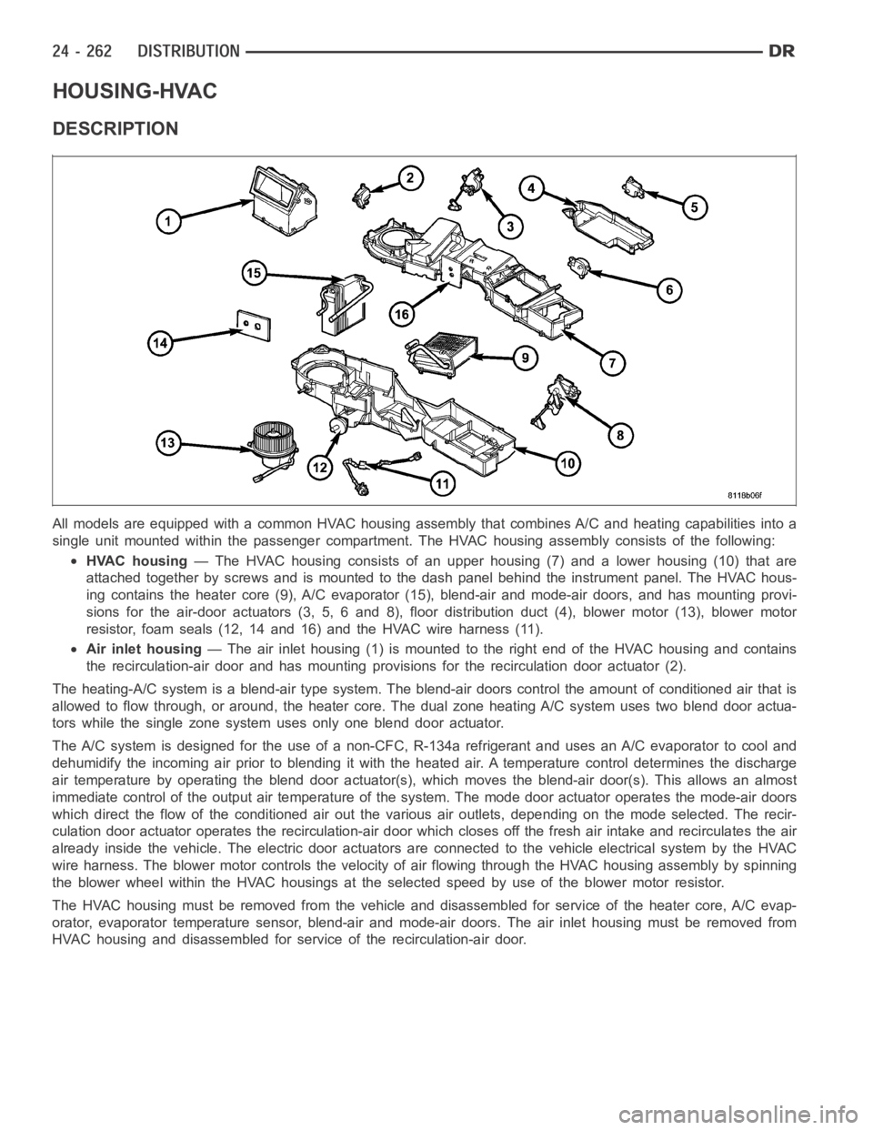
All models are equipped with a common HVAC housing assembly that combines A/C and heating capabilities into a
single unit mounted within the passenger compartment. The HVAC housing assembly consists of the following:
HVAC housing— The HVAC housing consists of an upper housing (7) and a lower housing (10) that are
attached together by screws and is mounted to the dash panel behind the instrument panel. The HVAC hous-
ing contains the heater core (9), A/C evaporator (15), blend-air and mode-air doors, and has mounting provi-
sions for the air-door actuators (3, 5, 6 and 8), floor distribution duct (4), blower motor (13), blower motor
resistor, foam seals (12, 14 and 16) and the HVAC wire harness (11).
Air inlet housing— The air inlet housing (1) is mounted to the right end of the HVAC housing andcontains
the recirculation-air door and has mounting provisions for the recirculation door actuator (2).
The heating-A/C system is a blend-air type system. The blend-air doors control the amount of conditioned air that is
allowed to flow through, or around, the heater core. The dual zone heating A/C system uses two blend door actua-
tors while the single zone system uses only one blend door actuator.
The A/C system is designed for the use of a non-CFC, R-134a refrigerant and uses an A/C evaporator to cool and
dehumidify the incoming air prior to blending it with the heated air. A temperature control determines the discharge
air temperature by operating the blend door actuator(s), which moves the blend-air door(s). This allows an almost
immediate control of the output air temperature of the system. The mode door actuator operates the mode-air doors
which direct the flow of the conditioned air out the various air outlets, depending on the mode selected. The recir-
culation door actuator operates the recirculation-air door which closesoff the fresh air intake and recirculates the air
already inside the vehicle. The electric door actuators are connected to the vehicle electrical system by the HVAC
wire harness. The blower motor controls the velocity of air flowing through the HVAC housing assembly by spinning
the blower wheel within the HVAC housings at the selected speed by use of theblower motor resistor.
The HVAC housing must be removed from the vehicle and disassembled for service of the heater core, A/C evap-
orator, evaporator temperature sensor, blend-air and mode-air doors. The air inlet housing must be removed from
HVAC housing and disassembled for service of the recirculation-air door.
Page 5104 of 5267
REMOVAL
HVAC HOUSING ASSEMBLY
WARNING: Refer to the applicable warnings and cautions for this system before performing the following
operation (Refer to 24 - HEATING & AIR CONDITIONING/PLUMBING - WARNINGS) and (Refer to 24 - HEAT-
ING & AIR CONDITIONING/PLUMBING - CAUTIONS). Failure to follow the warnings and cautions could result
in possible personal injury or death.
WARNING: On vehicles equipped with airbags, disable the airbag system before attempting any steering
wheel, steering column, or instrument panel component diagnosis or service. Disconnect and isolate the
negative battery (ground) cable, then wait two minutes for the airbag system capacitor to discharge before
performing further diagnosis or service. This is the only sure way to disable the airbag system. Failure to
take the proper precautions could result in accidental airbag deploymentand possible personal injury or
death.
NOTE: The HVAC housing must be removedfrom the vehicle and disassembled for service of the A/C evap-
orator, evaporator temperature sensor, mode-air and blend-air doors.
1. Recover the refrigerant from the refrigerant system
(Refer to 24 - HEATING & AIR CONDITIONING/
PLUMBING - STANDARD PROCEDURE -
REFRIGERANT SYSTEM RECOVERY).
2. Drain the engine cooling system (Refer to 7 -
COOLING - STANDARD PROCEDURE - COOL-
ING SYSTEM DRAIN).
3. Disconnect and isolate the negative battery cable.
4. Disconnect the A/C liquid line and the A/C accumu-
lator from the A/C evaporator (Refer to 24 - HEAT-
ING & AIR CONDITIONING/PLUMBING/LINE-A/C
LIQUID - REMOVAL) and (Refer to 24 - HEATING
& AIR CONDITIONING/PLUMBING/ACCUMULA-
TOR-A/C - REMOVAL).
5. Disconnect the heater hoses from the heater core
tubes.
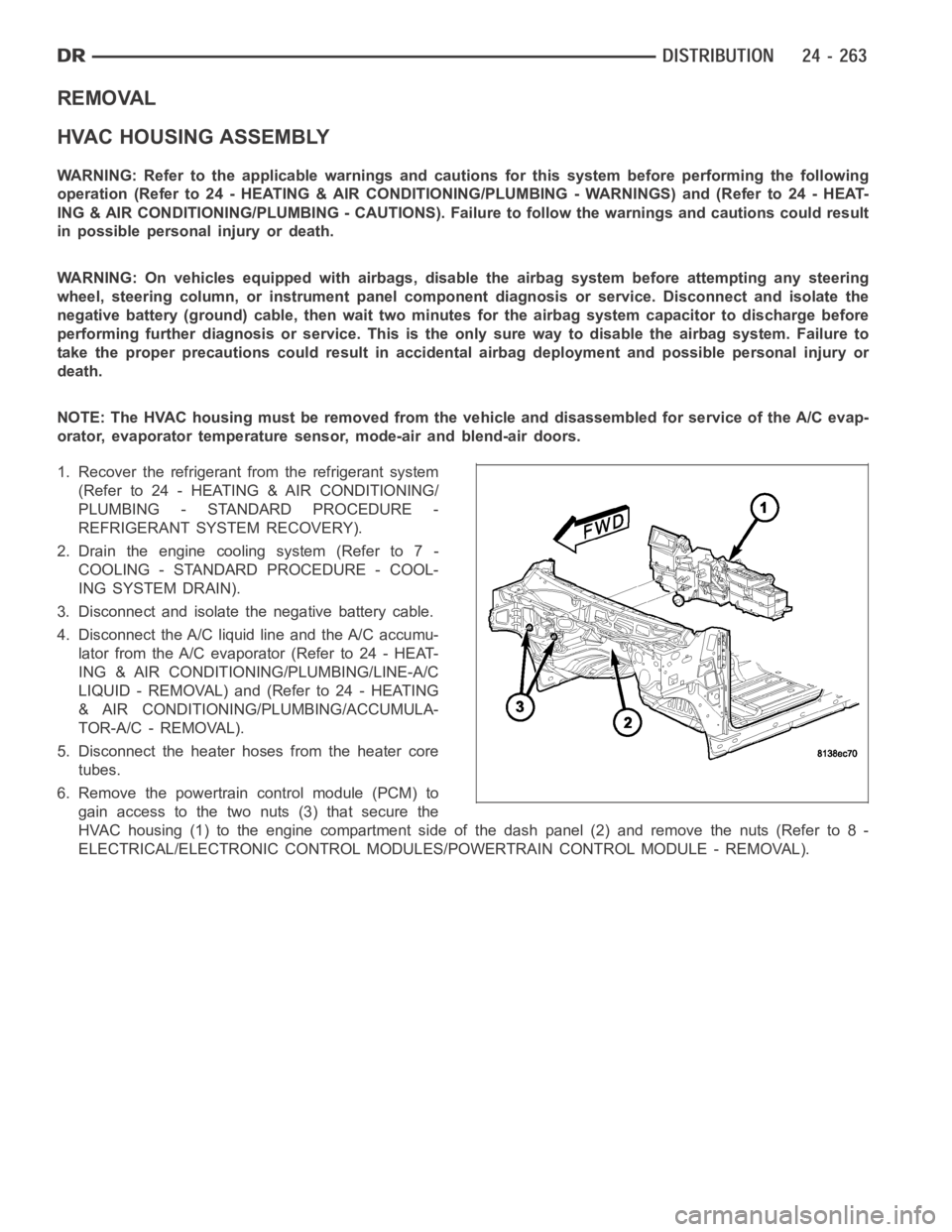
6. Remove the powertrain control module (PCM) to
gain access to the two nuts (3) that secure the
HVAC housing (1) to the engine compartment side of the dash panel (2) and remove the nuts (Refer to 8 -
ELECTRICAL/ELECTRONIC CONTROL MODULES/POWERTRAIN CONTROL MODULE - REMOVAL).
Page 5106 of 5267
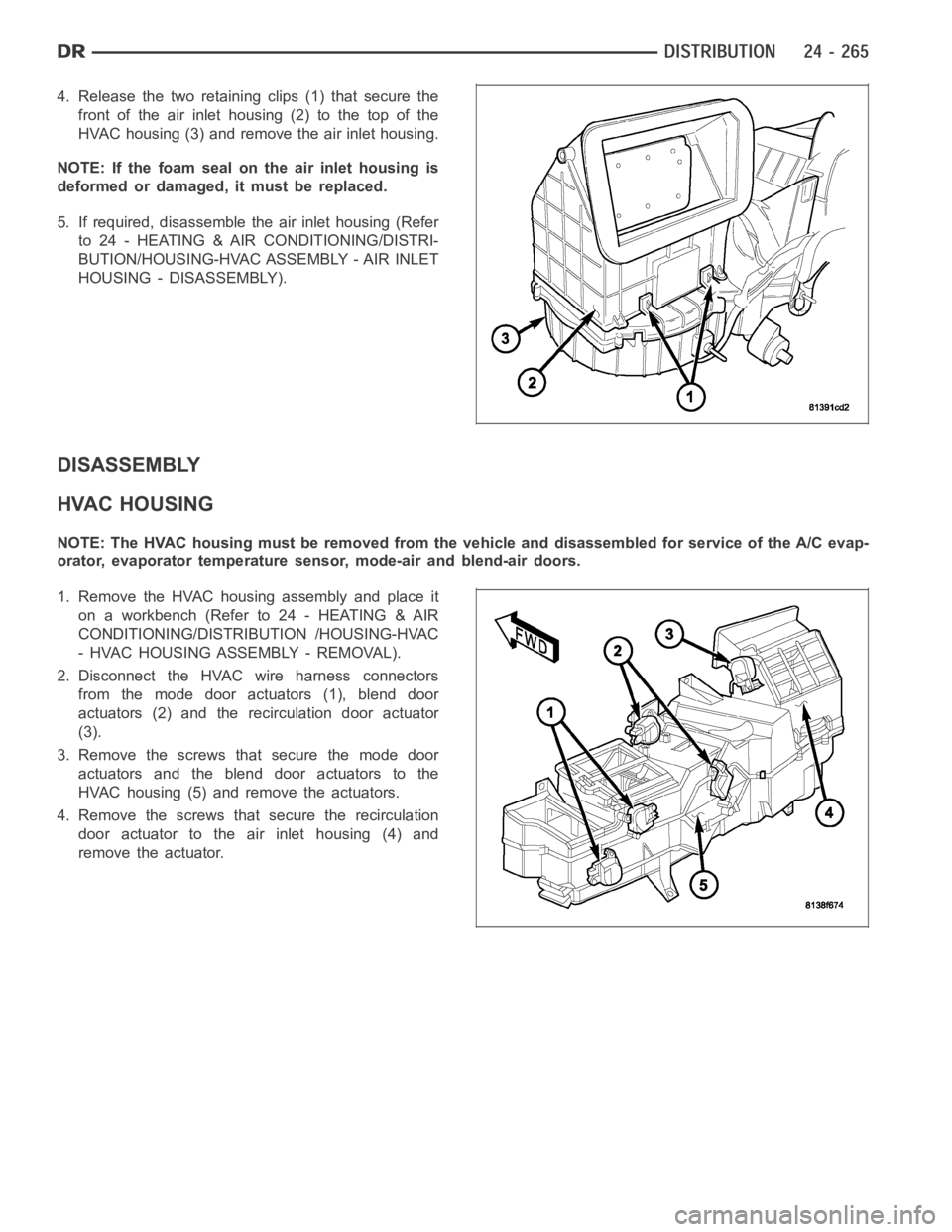
4. Release the two retaining clips (1) that secure the
front of the air inlet housing (2) to the top of the
HVAC housing (3) and remove the air inlet housing.
NOTE: If the foam seal on the air inlet housing is
deformed or damaged, it must be replaced.
5. If required, disassemblethe air inlet housing (Refer
to 24 - HEATING & AIR CONDITIONING/DISTRI-
BUTION/HOUSING-HVAC ASSEMBLY - AIR INLET
HOUSING - DISASSEMBLY).
DISASSEMBLY
HVAC HOUSING
NOTE: The HVAC housing must be removedfrom the vehicle and disassembled for service of the A/C evap-
orator, evaporator temperature sensor, mode-air and blend-air doors.
1. Remove the HVAC housing assembly and place it
on a workbench (Refer to 24 - HEATING & AIR
CONDITIONING/DISTRIBUTION /HOUSING-HVAC
- HVAC HOUSING ASSEMBLY - REMOVAL).
2. Disconnect the HVAC wire harness connectors
from the mode door actuators (1), blend door
actuators (2) and the recirculation door actuator
(3).
3. Remove the screws that secure the mode door
actuators and the blend door actuators to the
HVAC housing (5) and remove the actuators.
4. Remove the screws that secure the recirculation
door actuator to the air inlet housing (4) and
remove the actuator.
Page 5107 of 5267
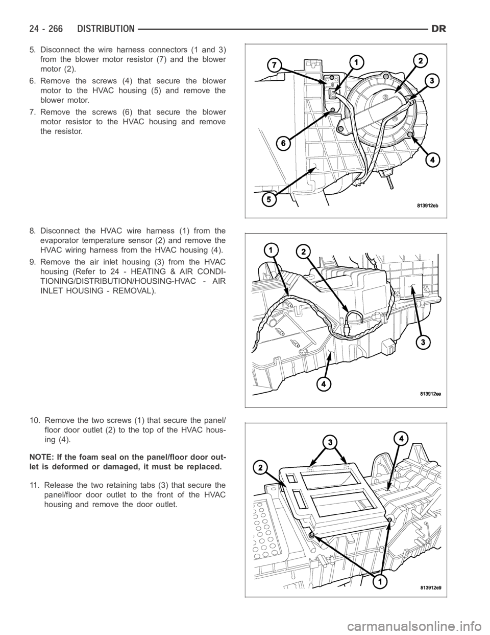
5. Disconnect the wire harness connectors (1 and 3)
from the blower motor resistor (7) and the blower
motor (2).
6. Remove the screws (4)that secure the blower
motor to the HVAC housing (5) and remove the
blower motor.
7. Remove the screws (6)that secure the blower
motor resistor to the HVAC housing and remove
the resistor.
8. Disconnect the HVAC wire harness (1) from the
evaporator temperature sensor (2) and remove the
HVAC wiring harness from the HVAC housing (4).
9. Remove the air inlet housing (3) from the HVAC
housing (Refer to 24 - HEATING & AIR CONDI-
TIONING/DISTRIBUTION/HOUSING-HVAC - AIR
INLET HOUSING - REMOVAL).
10. Remove the two screws (1) that secure the panel/
floor door outlet (2) to the top of the HVAC hous-
ing (4).
NOTE: If the foam seal on the panel/floor door out-
let is deformed or damaged, it must be replaced.
11. Release the two retaining tabs (3) that secure the
panel/floor door outlet to the front of the HVAC
housing and remove the door outlet.
Page 5111 of 5267
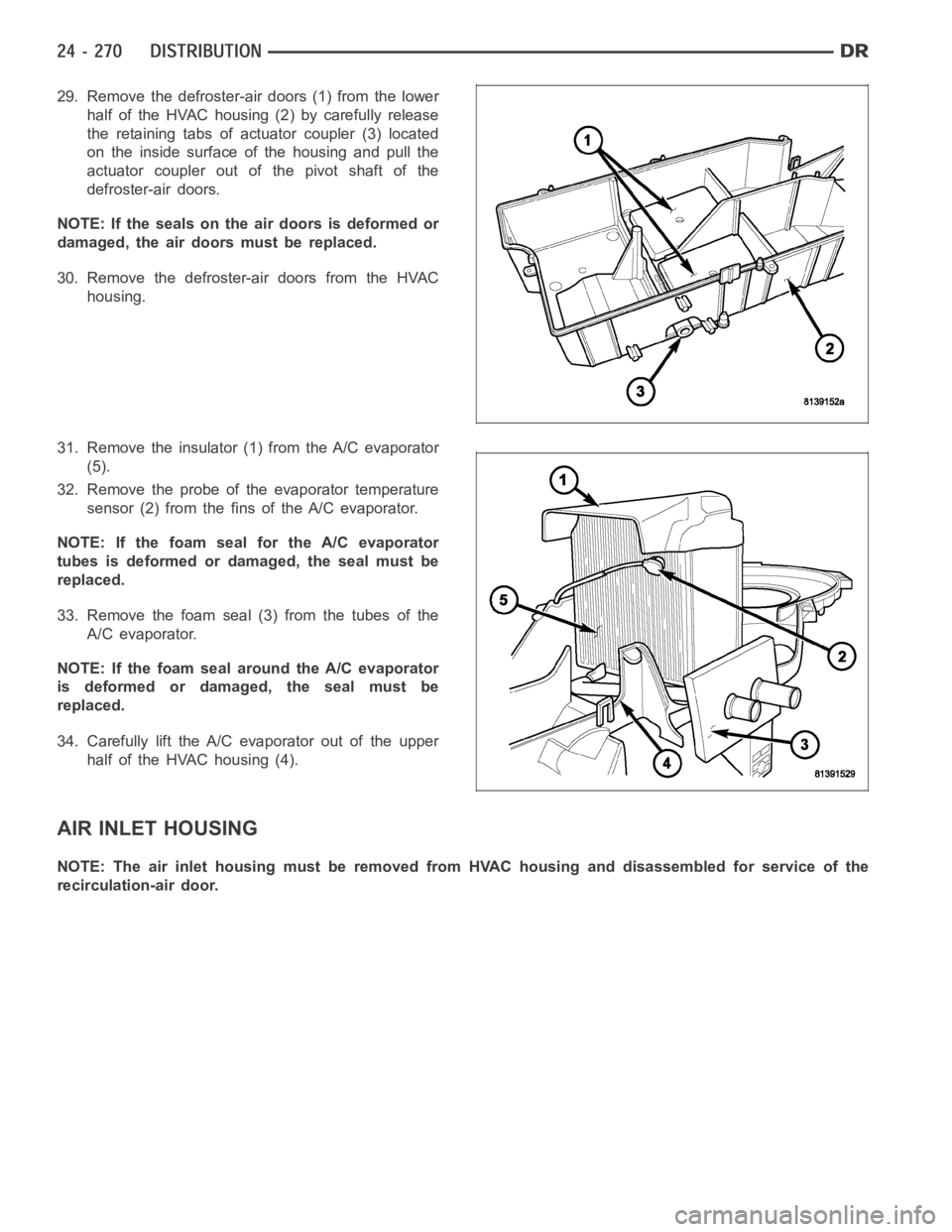
29. Remove the defroster-air doors (1) from the lower
half of the HVAC housing (2) by carefully release
the retaining tabs of actuator coupler (3) located
on the inside surface of the housing and pull the
actuator coupler out of the pivot shaft of the
defroster-air doors.
NOTE: If the seals on the air doors is deformed or
damaged, the air doors must be replaced.
30. Remove the defroster-air doors from the HVAC
housing.
31. Remove the insulator (1) from the A/C evaporator
(5).
32. Remove the probe of the evaporator temperature
sensor (2) from the fins of the A/C evaporator.
NOTE: If the foam seal for the A/C evaporator
tubes is deformed or damaged, the seal must be
replaced.
33. Remove the foam seal (3) from the tubes of the
A/C evaporator.
NOTE: If the foam seal around the A/C evaporator
is deformed or damaged, the seal must be
replaced.
34. Carefully lift the A/C evaporator out of the upper
half of the HVAC housing (4).
AIR INLET HOUSING
NOTE: The air inlet housing must be removed from HVAC housing and disassembled for service of the
recirculation-air door.