2006 DODGE RAM SRT-10 sensor
[x] Cancel search: sensorPage 4312 of 5267
MOTOR-SHIFT
DESCRIPTION
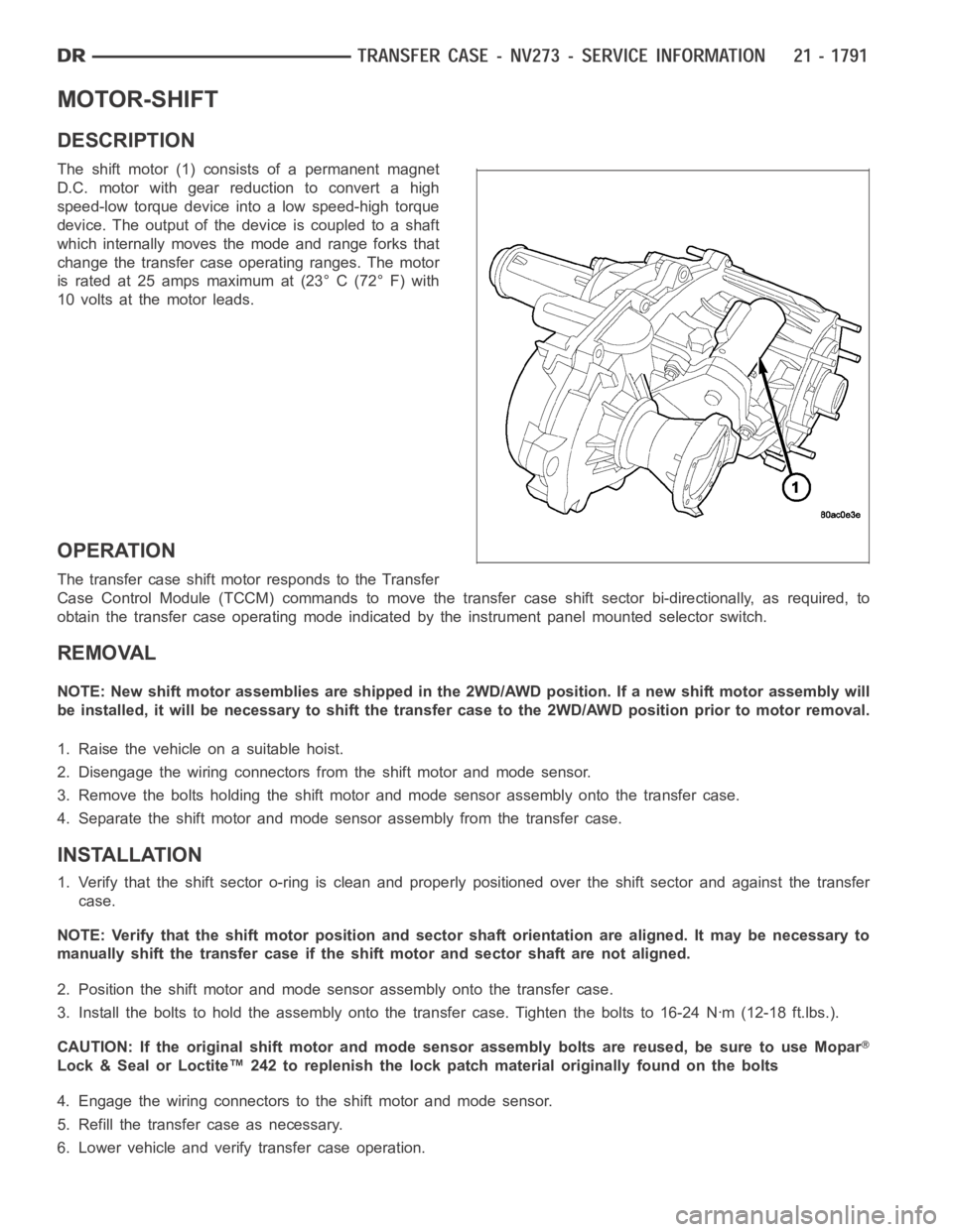
The shift motor (1) consists of a permanent magnet
D.C. motor with gear reduction to convert a high
speed-low torque device into a low speed-high torque
device. The output of the device is coupled to a shaft
which internally moves the mode and range forks that
change the transfer case operating ranges. The motor
is rated at 25 amps maximum at (23° C (72° F) with
10 volts at the motor leads.
OPERATION
The transfer case shift motor responds to the Transfer
Case Control Module (TCCM) commands to move the transfer case shift sectorbi-directionally, as required, to
obtain the transfer case operating mode indicated by the instrument panelmounted selector switch.
REMOVAL
NOTE: New shift motor assemblies are shipped in the 2WD/AWD position. If a new shift motor assembly will
be installed, it will be necessary to shift the transfer case to the 2WD/AWDposition prior to motor removal.
1. Raise the vehicle on a suitable hoist.
2. Disengage the wiring connectors from the shift motor and mode sensor.
3. Remove the bolts holding the shift motor and mode sensor assembly onto the transfer case.
4. Separate the shift motor and mode sensor assembly from the transfer case.
INSTALLATION
1. Verify that the shift sector o-ring is clean and properly positioned over the shift sector and against the transfer
case.
NOTE: Verify that the shift motor position and sector shaft orientation are aligned. It may be necessary to
manually shift the transfer case if the shift motor and sector shaft are notaligned.
2. Position the shift motor and mode sensor assembly onto the transfer case.
3. Install the bolts to hold the assembly onto the transfer case. Tighten the bolts to 16-24 Nꞏm (12-18 ft.lbs.).
CAUTION: If the original shift motor and mode sensor assembly bolts are reused, be sure to use Mopar
Lock & Seal or Loctite™ 242 to replenish the lock patch material originallyfound on the bolts
4. Engage the wiring connectors to the shift motor and mode sensor.
5. Refill the transfer case as necessary.
6. Lower vehicle and verify transfer case operation.
Page 4333 of 5267

STUDS
REMOVAL
1. Raise and support the vehicle.
2. Remove the wheel and tire assembly.
3. Remove the brake caliper, caliper adapter and
rotor, (Refer to 5 - BRAKES/HYDRAULIC/ME-
CHANICAL/ROTORS - REMOVAL).
4. Remove the wheel speed sensor from the hub.
5. Press the stud from the hub using remover
C-4150A (1).
6. Remove the stud (2) from the hub (1) through the
backing plate access hole (3).
INSTALLATION
1. Install the new stud (2) into the hub flange (1).
2. Install three proper sized washers onto the stud,
then install lug nut with the flat side of the nut
against the washers.
3. Tighten the lug nut until the stud is pulled into the
hub flange. Verify that the stud is properly seated
into the flange.
4. Remove the lug nut and washers.
5. Install the brake rotor, caliper adapter, and caliper,
(Refer to 5 - BRAKES/HYDRAULIC/MECHANICAL/
ROTORS - INSTALLATION).
6. Install the wheel speed sensor.
7. Install the wheel and tire assembly, use new lug nut on the stud or studs that were replaced.
Page 4469 of 5267
HOOD
REMOVAL
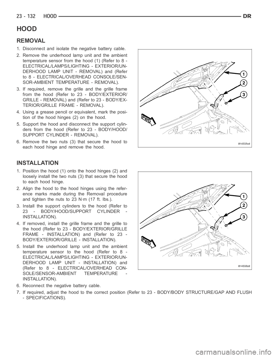
1. Disconnect and isolate the negative battery cable.
2. Remove the underhood lamp unit and the ambient
temperature sensor from the hood (1) (Refer to 8 -
ELECTRICAL/LAMPS/LIGHTING - EXTERIOR/UN-
DERHOOD LAMP UNIT - REMOVAL) and (Refer
to 8 - ELECTRICAL/OVERHEAD CONSOLE/SEN-
SOR-AMBIENT TEMPERATURE - REMOVAL).
3. If required, remove the grille and the grille frame
from the hood (Refer to 23 - BODY/EXTERIOR/
GRILLE - REMOVAL) and (Refer to 23 - BODY/EX-
TERIOR/GRILLE FRAME - REMOVAL).
4. Using a grease pencil or equivalent, mark the posi-
tion of the hood hinges (2) on the hood.
5. Support the hood and disconnect the support cylin-
ders from the hood (Refer to 23 - BODY/HOOD/
SUPPORT CYLINDER - REMOVAL).
6. Remove the two nuts (3) that secure the hood to
each hood hinge and remove the hood.
INSTALLATION
1. Position the hood (1) onto the hood hinges (2) and
loosely install the two nuts (3) that secure the hood
to each hood hinge.
2. Align the hood to the hood hinges using the refer-
ence marks made during the Removal procedure
and tighten the nuts to 23 Nꞏm (17 ft. lbs.).
3. Install the support cylinders to the hood (Refer to
23 - BODY/HOOD/SUPPORT CYLINDER -
INSTALLATION).
4. If removed, install the grille frame and the grille to
the hood (Refer to 23 - BODY/EXTERIOR/GRILLE
FRAME - INSTALLATION) and (Refer to 23 -
BODY/EXTERIOR/GRILLE - INSTALLATION).
5. Install the underhood lamp unit and the ambient
temperature sensor to the hood (Refer to 8 -
ELECTRICAL/LAMPS/LIGHTING - EXTERIOR/UN-
DERHOOD LAMP UNIT - INSTALLATION) and
(Refer to 8 - ELECTRICAL/OVERHEAD CON-
SOLE/SENSOR-AMBIENT TEMPERATURE -
INSTALLATION).
6. Reconnect the negative battery cable.
7. If required, adjust the hood to the correct position (Refer to 23 - BODY/BODY STRUCTURE/GAP AND FLUSH
- SPECIFICATIONS).
Page 4559 of 5267
SEATS
WARNING
WARNINGS - RESTRAINT SYSTEM
WARNING: To avoid personal injury or death, during and following any seat beltorchildrestraintanchor
service, carefully inspect all seat belts, buckles, mounting hardware, retractors, tether straps, and anchors
for proper installation, operation, or damage. Replace any belt that is cut, frayed, or torn. Straighten any
belt that is twisted. Tighten any loose fasteners. Replace any belt that has a damaged or ineffective buckle
or retractor. Replace any belt that has a bent or damaged latch plate or anchor plate. Replace any child
restraint anchor or the unit to which the anchor is integral that has been bent or damaged. Never attempt to
repair a seat belt or child restraint component. Always replace damaged orineffective seat belt and child
restraint components with the correct, new and unused replacement parts listed in the DaimlerChrysler
Mopar
Parts Catalog.
WARNING: To avoid personal injury or death, on vehicles equipped with airbags, disable the supplemental
restraint system before attempting any steering wheel, steering column,airbag, seat belt tensioner, impact
sensor, or instrument panel component diagnosis or service. Disconnect and isolate the battery negative
(ground) cable, then wait two minutes for the system capacitor to discharge before performing further diag-
nosis or service. This is the only sure way to disable the supplemental restraint system. Failure to take the
proper precautions could result in accidental airbag deployment.
WARNING: To avoid personal injury or death on vehicles equipped with airbags, before performing any
welding operations disconnect and isolate the battery negative (ground)cable and disconnect all wire har-
ness connectors from the Occupant Restraint Controller (ORC). Failure totake the proper precautions could
result in accidental airbag deployment and other possible damage to the supplemental restraint system cir-
cuits and components.
WARNING: To avoid personal injury or death, do not attempt to dismantle an airbag unit or tamper with its
inflator. Do not puncture, incinerate, or bring into contact with electricity. Do not store at temperatures
exceeding 93° C (200° F). An airbag inflator unit may contain sodium azide and potassium nitrate. These
materials are poisonous and extremely flammable. Contact with acid, water, or heavy metals may produce
harmful and irritating gases (sodium hydroxide is formed in the presence of moisture) or combustible com-
pounds. An airbag inflator unit may also contain a gas canister pressurizedtoover2500psi.
WARNING: To avoid personal injury or death, when handling a seat belt tensioner retractor, proper care
should be exercised to keep fingers out from under the retractor cover and away from the seat belt webbing
where it exits from the retractor cover.
WARNING: To avoid personal injury or death, replace all restraint system components only with parts spec-
ified in the DaimlerChrysler Mopar
Parts Catalog. Substitute parts may appear interchangeable, but internal
differences may result in inferior occupant protection.
WARNING: To avoid personal injury or death, the fasteners, screws, and bolts originally used for the
restraint system components must never be replaced with any substitutes.These fasteners have special
coatings and are specifically designed for the restraint system. Any timea new fastener is needed, replace
it with the correct fasteners provided in the service package or specifiedin the DaimlerChrysler Mopar
Parts Catalog.
WARNING: To avoid personal injury or death, when a steering column has an airbag unit attached, never
place the column on the floor or any other surface with the steering wheel orairbag unit face down.
Page 4843 of 5267
B1016–REAR DEFROST SWITCH REQUEST
INPUT CIRCUIT LOW (SINGLE-ZONE)....... 105
B1031–EVAPORATOR TEMPERATURE
SENSOR CIRCUIT LOW.................... 107
B1032–EVAPORATOR TEMPERATURE
SENSOR CIRCUIT HIGH.................... 110
B1040–PANEL MODE DOOR 1 CONTROL
CIRCUIT/PERFORMANCE. . ................ 114
B1041–PANEL MODE DOOR 1 CONTROL
CIRCUIT LOW (DUAL-ZONE)................ 115
B1041–PANEL MODE DOOR 1 CONTROL
CIRCUIT LOW (SINGLE-ZONE).............. 119
B1042–PANEL MODE DOOR 1 CONTROL
CIRCUIT HIGH (DUAL-ZONE)............... 123
B1042–PANEL MODE DOOR 1 CONTROL
CIRCUIT HIGH (SINGLE-ZONE)............. 126
B1043–PANEL MODE DOOR 1 CONTROL
CIRCUIT OPEN (DUAL-ZONE).............. 129
B1043–PANEL MODE DOOR 1 CONTROL
CIRCUIT OPEN (SINGLE-ZONE)............ 132
B 1 0 4 4 – PA N E L M O D E D O O R 1 T R AV E L
RANGE TOO SMALL....................... 135
B 1 0 4 5 – PA N E L M O D E D O O R 1 T R AV E L
RANGE TOO LARGE....................... 137
B1046–FLOOR/DEFROST MODE DOOR
CONTROL CIRCUIT/PERFORMANCE........ 139
B1047–FLOOR/DEFROST MODE DOOR
CONTROL CIRCUIT LOW (DUAL-ZONE)..... 140
B1047–FLOOR/DEFROST MODE DOOR
CONTROL CIRCUIT LOW (SINGLE-ZONE)... 144
B1048–FLOOR/DEFROST MODE DOOR
CONTROL CIRCUIT HIGH (DUAL-ZONE)..... 148
B1048–FLOOR/DEFROST MODE DOOR
CONTROL CIRCUIT HIGH (SINGLE-ZONE)... 151
B1049–FLOOR/DEFROST MODE DOOR
CONTROL CIRCUIT OPEN (DUAL-ZONE).... 154
B1049–FLOOR/DEFROST MODE DOOR
CONTROL CIRCUIT OPEN (SINGLE-
ZONE).................................... 157
B1050–BLEND DOOR TRAVEL RANGE TOO
SMALL (SINGLE-ZONE).................... 160
B1051–BLEND DOOR TRAVEL RANGE TOO
LARGE (SINGLE-ZONE).................... 162
B1058–RECIRCULATION DOOR CONTROL
CIRCUIT/PERFORMANCE.................. 164
B1059–RECIRCULATION DOOR CONTROL
CIRCUIT LOW (DUAL-ZONE)................ 165
B1059–RECIRCULATION DOOR CONTROL
CIRCUIT LOW (SINGLE-ZONE).............. 169
B1060–CLIMATE CONTROL MOTOR(S)
COMMON 1 CONTROL CIRCUIT HIGH
(DUAL-ZONE).............................. 173B1060–CLIMATE CONTROL MOTOR(S)
COMMON 1 CONTROL CIRCUIT HIGH
(SINGLE-ZONE)............................ 176
B1061–CLIMATE CONTROL MOTOR(S)
COMMON 1 CONTROL CIRCUIT OPEN
(DUAL-ZONE).............................. 179
B1061–CLIMATE CONTROL MOTOR(S)
COMMON 1 CONTROL CIRCUIT OPEN
(SINGLE-ZONE)............................ 186
B1079–CLIMATE CONTROL COOL DOWN
TEST EXCESSIVE TIME (SINGLE-ZONE). . . . 192
B2214–(HVAC) CLIMATE CONTROL
INTERNAL................................. 194
U0019–CAN B BUS ........................ 195
U0141–LOST COMMUNICATION WITH
FRONT CONTROL MODULE................ 197
U0151–LOST COMMUNICATION WITH
OCCUPANT RESTRAINT CONTROLLER
(ORC)..................................... 198
U0154–LOST COMMUNICATION WITH
OCCUPANT CLASSIFICATION MODULE
..... 198
U0155–LOST COMMUNICATION WITH
CLUSTER/CCN............................ 198
U0156–LOST COMMUNICATION WITH EOM . 198
U0168–LOST COMMUNICATION WITH
VEHICLE SECURITY CONTROL MODULE
(SKREEM/WCM)........................... 198
U0169–LOST COMMUNICATION WITH
SUNROOF CONTROL MODULE............. 199
U0184–LOST COMMUNICATION WITH
RADIO.................................... 199
U0186–LOST COMMUNICATION WITH
AUDIO AMPLIFIER......................... 199
U0195–LOST COMMUNICATION WITH
SDARS.................................... 199
U0196–LOST COMMUNICATION WITH
VEHICLE ENTERTAINMENT CONTROL
MODULE.................................. 199
U0197–LOST COMMUNICATION WITH
HANDS FREE PHONE MODULE............ 200
DTC SET DURING ROUTINE - TEST NOT
PASSED.................................. 200
BLOWERS NOT ON HIGH - TEST NOT RUN . 200
REFRIGERANT TEMPERATURE SENSOR
ERROR................................... 200
*BLOWER MOTOR INOPERATIVE ........... 201
*HVAC SYSTEM TEST ..................... 205
Page 4881 of 5267
B10B2–A/C COOL DOWN TEST PERFORMANCE (DUAL-ZONE)
For a complete wiring diagramRefer to Section 8W.
Theory of Operation
The Cooldown Test checks A/C system performance based on Evaporator Temperature Sensor input. The main cri-
teria is to lower evaporator temperature 11.11°C (20°F) within one minute. Before starting the test, the evaporator
temperature must be above 13°C (55°F) and the front blower speed must be setto high speed. When the test is
running, A/C Select and A/C Request will be on and the A/C status indicator will flash. When the test is complete,
the scan tool will display one or more test status messages to indicate the outcome of the Cooldown Test. A Suc-
cessful Cooldown – Test Passed status message indicates that the main testcriteria was met. A DTC Set During
Routine – Test Not Passed status message indicates that the A/C system is unable to lower the evaporator tem-
perature 11.11°C (20°F) within one minute. A Conditions Too Cold – Test NotRun status message indicates that the
evaporator temperature was below 13°C (55°F) when starting the Cooldown Test. A Blowers Not On High – Test Not
Run status message indicates that either the front blower speed was not setto high speed prior to starting the
Cooldown Test or the front blower speed was changed from high speed to another setting after starting the
Cooldown test. A Refrigerant Temperature Sensor Error status message indicates that a fault occurred with the
Evaporator Temperature Sensor/sensor circuits. A No Results Stored/Test Not Complete status message indicates
that the power was cycled while the test was running.
When Monitored:
When the Cooldown Test is executed.
Set Condition:
If the A/C system is unable to lower the evaporator temperature 11.11°C (20°F) within one minute.
Possible Causes
OTHER HVAC SYSTEM FAULTS PRESENT
EVAPORATOR TEMPERATURE SENSOR CIRCUITS
EVAPORATOR TEMPERATURE SENSOR
TOTALLY INTEGRATED POWER MODULE (TIPM) FAULTS PRESENT
POWERTRAIN SYSTEM FAULTS PRESENT
Diagnostic Test
1.DIAGNOSE COOLDOWN TEST STATUS MESSAGES
WereanyofthefollowingstatusmessagespresentafterperformingtheCooldown Test?
Yes, Conditions Too Cold - Test Not Run
If running, turn the A/C compressor off. Verify that the work area ambient temperature is above 15.6°C
(60°F). If not, move the vehicle to a warmer work area. Verify that the evaporator temperature is above
13°C (55°F). If not, set the blower to high speed and allow the blower to run for five minutes. Then, run
the Cooldown Test again.
Yes, Blowers Not On High - Test Not Run
Set the blower speed to high speed and then run the Cooldown Test again.
Yes, No Results Stored/Test Not Complete
Verify that power is not interrupted while rerunning the Cooldown Test.
No>>
Go To 2
Page 4948 of 5267
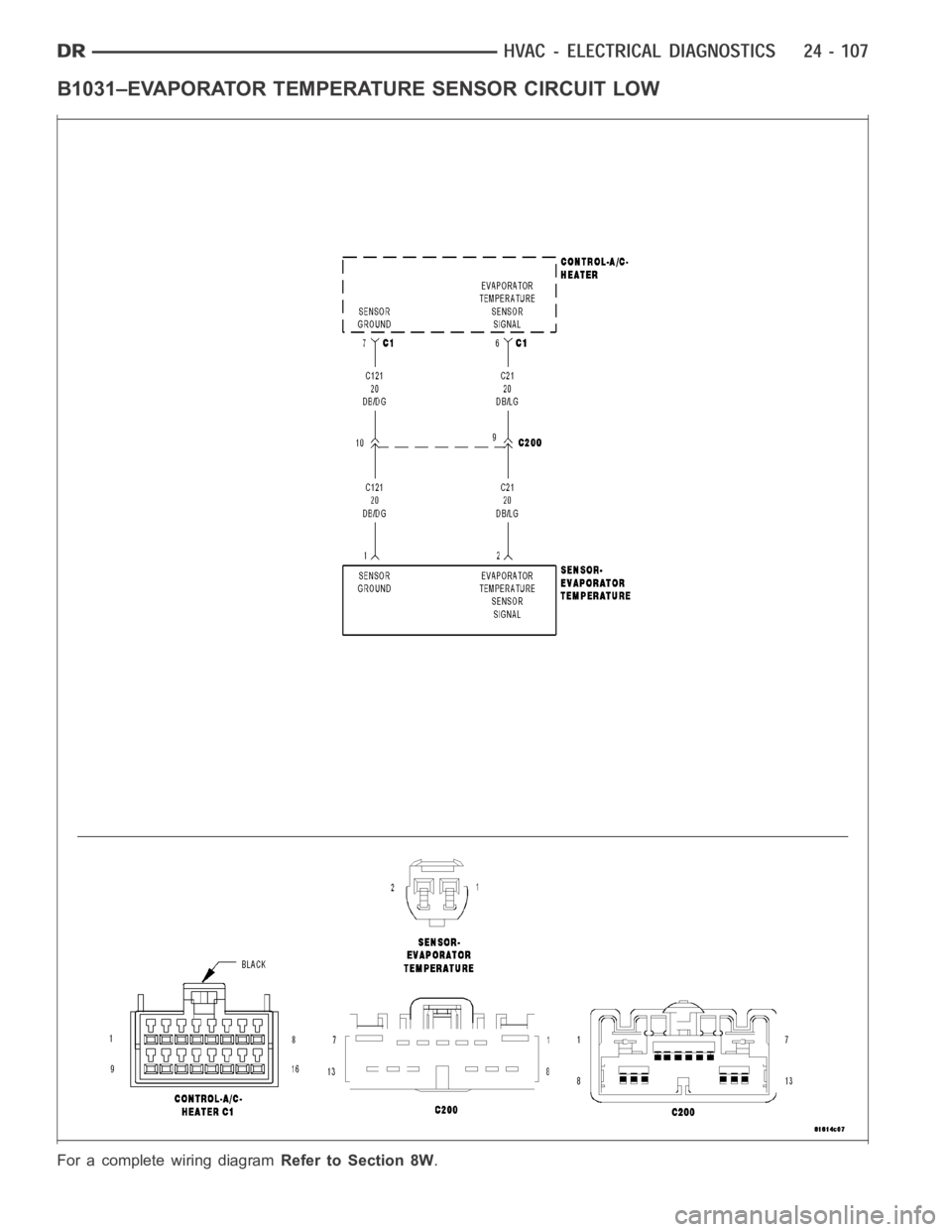
B1031–EVAPORATOR TEMPERATURE SENSOR CIRCUIT LOW
For a complete wiring diagramRefer to Section 8W.
Page 4949 of 5267
When Monitored:
With the ignition on.
Set Condition:
If the Evaporator Temperature Sensor input is out of range toward the low voltage threshold, (A/D counts reach
low threshold of 3). This DTC has a maturing time of 5 seconds and a de-maturing time of 10 seconds. If the
DTC’s status changes from active to stored it will stay in memory for 100 ignition cycles.
Possible Causes
(C21) EVAPORATOR TEMPERATURE SENSOR SIGNAL CIRCUIT SHORTED TO GROUND
(C21) EVAPORATOR TEMPERATURE SENSOR SIGNAL CIRCUIT SHORTED TO (C121) SENSOR GROUND
CIRCUIT
EVAPORATOR TEMPERATURE SENSOR
A/C HEATER CONTROL
NOTE: This DTC must be active for the results of this test to be valid. Do not perform this test if this DTC
is stored. Refer to HVAC System Test for stored DTC test procedures.
Diagnostic Test
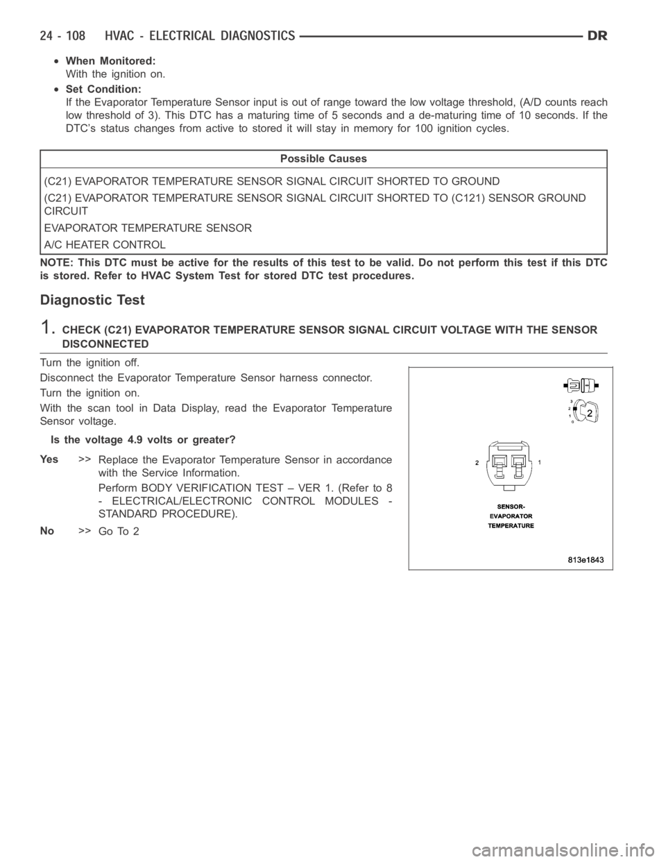
1.CHECK (C21) EVAPORATOR TEMPERATURE SENSOR SIGNAL CIRCUIT VOLTAGE WITH THE SENSOR
DISCONNECTED
Turn the ignition off.
Disconnect the Evaporator Temperature Sensor harness connector.
Turn the ignition on.
With the scan tool in Data Display, read the Evaporator Temperature
Sensor voltage.
Is the voltage 4.9 volts or greater?
Ye s>>
Replace the Evaporator Temperature Sensor in accordance
with the Service Information.
Perform BODY VERIFICATION TEST – VER 1. (Refer to 8
- ELECTRICAL/ELECTRONIC CONTROL MODULES -
STANDARD PROCEDURE).
No>>
Go To 2