Page 4166 of 5267
9. Install skid plate, if equipped. (Refer to 13 - FRAMES & BUMPERS/FRAME/TRANSFER CASE SKID PLATE -
INSTALLATION)
10. Lower vehicle
SPECIFICATIONS
TRANSFER CASE - NV271
TORQUE SPECIFICATIONS
DESCRIPTION N-m Ft. Lbs. In. Lbs.
Plug, Detent 16-25 12-18 -
Plug, Drain/Fill 20-34 15-25 -
Bolt, Extension Housing 27-34 20-25 -
Bolt, Case Half 27-34 20-25 -
Nut, Range Lever 27-34 20-25 -
Sector Support 27-34 20-25 -
Nuts, Mounting 30-41 20-30 -
Position Sensor 20-34 15-25 -
Nut, Companion Flange 176-271 130-200 -
Page 4172 of 5267
SENSOR-POSITION
DESCRIPTION
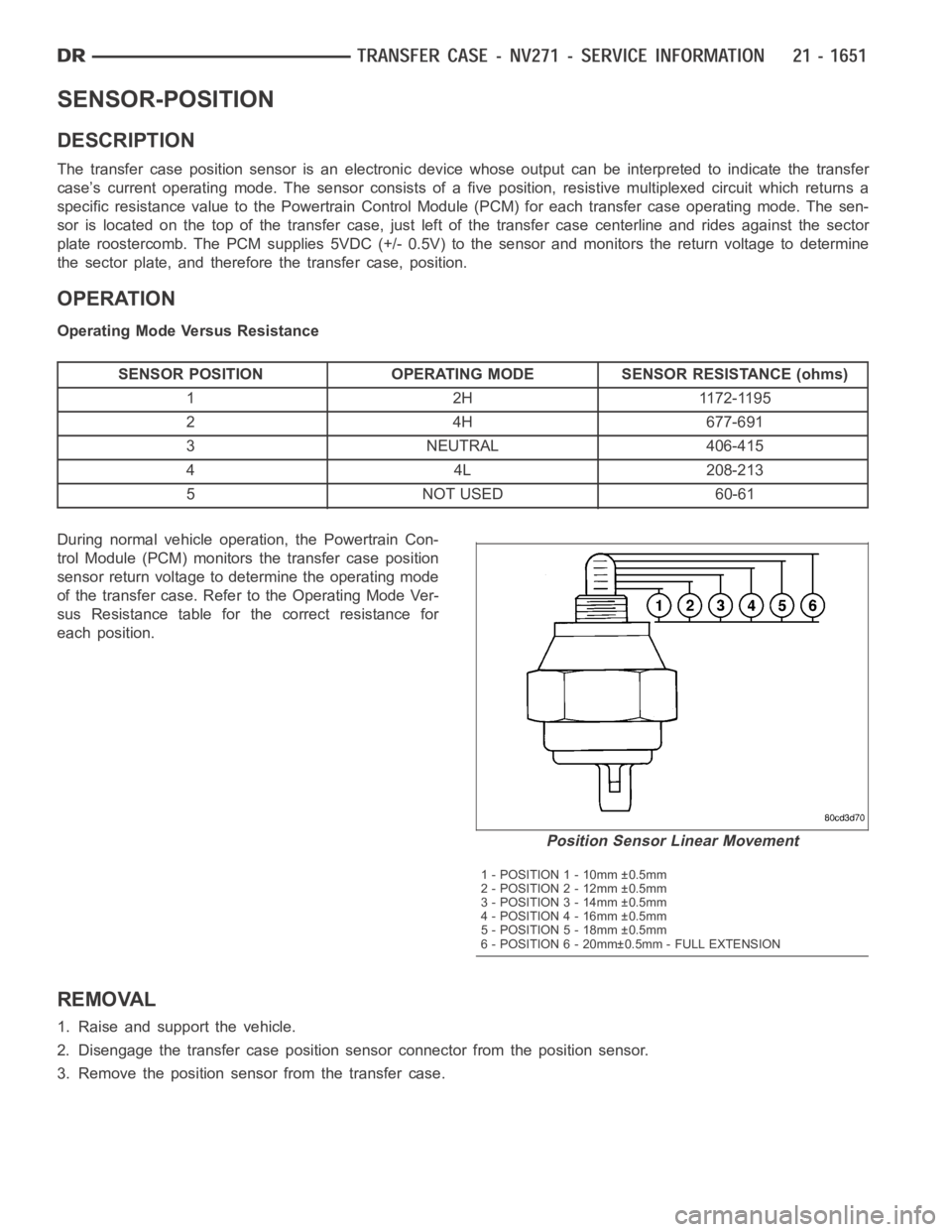
The transfer case position sensor is an electronic device whose output canbe interpreted to indicate the transfer
case’s current operating mode. The sensor consists of a five position, resistive multiplexed circuit which returns a
specific resistance value to the Powertrain Control Module (PCM) for eachtransfer case operating mode. The sen-
sor is located on the top of the transfer case, just left of the transfer casecenterline and rides against the sector
plate roostercomb. The PCM supplies 5VDC (+/- 0.5V) to the sensor and monitors the return voltage to determine
the sector plate, and therefore the transfer case, position.
OPERATION
Operating Mode Versus Resistance
SENSOR POSITION OPERATING MODE SENSOR RESISTANCE (ohms)
1 2H 1172-1195
24H677-691
3 NEUTRAL 406-415
44L208-213
5 NOT USED 60-61
During normal vehicle operation, the Powertrain Con-
trol Module (PCM) monitors the transfer case position
sensor return voltage to determine the operating mode
of the transfer case. Refer to the Operating Mode Ver-
sus Resistance table for the correct resistance for
each position.
REMOVAL
1. Raise and support the vehicle.
2. Disengage the transfer case position sensor connector from the positionsensor.
3. Remove the position sensor from the transfer case.
Position Sensor Linear Movement
1 - POSITION 1 - 10mm ±0.5mm
2 - POSITION 2 - 12mm ±0.5mm
3 - POSITION 3 - 14mm ±0.5mm
4 - POSITION 4 - 16mm ±0.5mm
5 - POSITION 5 - 18mm ±0.5mm
6 - POSITION 6 - 20mm±0.5mm - FULL EXTENSION
Page 4173 of 5267
INSTALLATION
1. Inspect the o-ring seal on the transfer case position sensor. Replace the o-ring if necessary.
2. Install the transfer case position sensor into the transfer case. Torque the sensor to 27 Nꞏm (20 ft.lbs.).
3. Engage the transfer case position sensor connector to the position sensor.
4. Lower vehicle.
5. Verify proper sensor operation.
Page 4177 of 5267
page page
TRANSFER CASE - NV243 - SERVICE
INFORMATION
DESCRIPTION ............................. 1657
OPERATION ............................... 1657
DIAGNOSIS AND TESTING - TRANSFER
CASE - NV243 ............................ 1658
REMOVAL ................................. 1659
DISASSEMBLY ............................. 1659
CLEANING ................................. 1671
INSPECTION ............................... 1671
ASSEMBLY . ............................... 1674
INSTALLATION ............................. 1686
SPECIFICATIONS
TRANSFER CASE - NV243 ................ 1686
SPECIAL TOOLS
TRANSFER CASE - NV243 ................ 1687
SEAL-EXTENSION HOUSING
REMOVAL ................................. 1689
INSTALLATION ............................. 1689
FLUID
STANDARD PROCEDURE - FLUID DRAIN AND
REFILL ................................... 1690SEAL-FRONT OUTPUT SHAFT
REMOVAL ................................. 1691
INSTALLATION ............................. 1692
SENSOR-MODE
DESCRIPTION ............................. 1693
OPERATION ............................... 1693
SWITCH-SELECTOR
DESCRIPTION ............................. 1695
OPERATION ............................... 1695
MOTOR-SHIFT
DESCRIPTION ............................. 1697
OPERATION ............................... 1697
REMOVAL ................................. 1697
INSTALLATION ............................. 1697
ASSEMBLY-SHIFT MOTOR/MODE SENSOR
DESCRIPTION ............................. 1699
OPERATION ............................... 1699
Page 4178 of 5267
TRANSFER CASE - NV243 - SERVICE INFORMATION
DESCRIPTION
The NV243 is an electronically controlled part-time transfer case with a low range gear reduction system. The
NV243 has three operating ranges plus a NEUTRAL position. The low range system provides a gear reduction ratio
for increased low speed torque capability.
The geartrain is mounted in two aluminum case halves attached with bolts. The mainshaft front and rear bearings
are mounted in aluminum retainer housings bolted to the case halves.
OPERATING RANGES
Transfer case operating ranges are:
2WD (2-wheel drive).
4HI (4-wheel drive).
4LO (4-wheel drive low range).
NEUTRAL.
The 2WD range is for use on any road surface at any time.
The 4HI and 4LO ranges are for off road use only. They are not for use on hard surface roads. The only exception
being when the road surface is wet or slippery or covered by ice and snow.
The low range reduction gear system is operative in 4LO range only. This range is for extra pulling power in off road
situations. Low range reduction ratio is 2.72:1.
SHIFT MECHANISM
Operating ranges are selected with a dash mounted shift selector switch. The shift selector switch provides a input
to the Transfer Case Control Module (TCCM) to indicate the driver’s desireto change operating ranges. The TCCM
uses this input, along with input from the transfer case mounted mode sensor and information from the vehicle’s
bus, to determine if a shift is permitted. If the TCCM decides the shift is permitted, the TCCM controls the shift
motor, mounted to the exterior of the transfer case, to perform the shift.
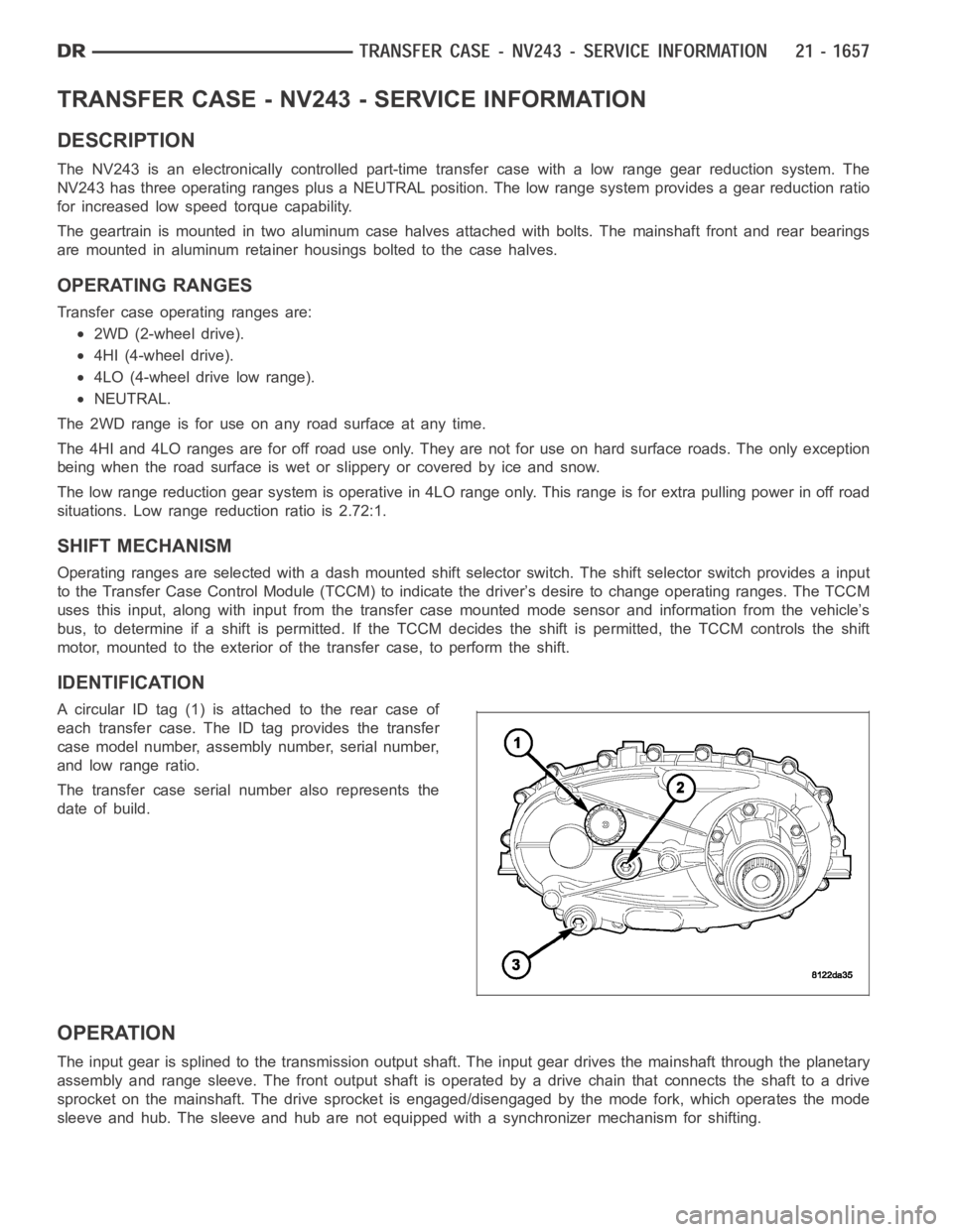
IDENTIFICATION
A circular ID tag (1) is attached to the rear case of
each transfer case. The ID tag provides the transfer
case model number, assembly number, serial number,
and low range ratio.
The transfer case serial number also represents the
date of build.
OPERATION
The input gear is splined to the transmission output shaft. The input gear drives the mainshaft through the planetary
assembly and range sleeve. The front output shaft is operated by a drive chain that connects the shaft to a drive
sprocket on the mainshaft. The drive sprocket is engaged/disengaged by themodefork,whichoperatesthemode
sleeve and hub. The sleeve and hub are not equipped with a synchronizer mechanism for shifting.
Page 4180 of 5267
REMOVAL
1. Shift transfer case into 2WD.
2. Raise vehicle.
3. Drain transfer case lubricant.
4. Mark front and rear propeller shafts for alignment
reference.
5. Support transmission with jack stand.
6. Remove the transfer case skid plate, if equipped.
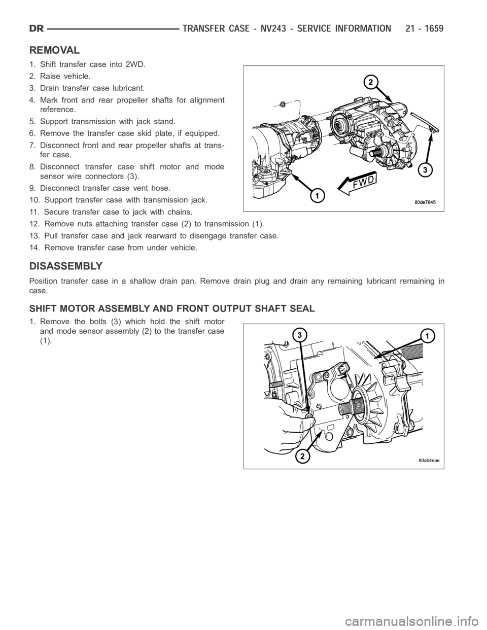
7. Disconnect front and rear propeller shafts at trans-
fer case.
8. Disconnect transfer case shift motor and mode
sensor wire connectors (3).
9. Disconnect transfer case vent hose.
10. Support transfer case with transmission jack.
11. Secure transfer case to jack with chains.
12. Remove nuts attaching transfer case (2) to transmission (1).
13. Pull transfer case and jack rearward to disengage transfer case.
14. Remove transfer case from under vehicle.
DISASSEMBLY
Position transfer case in a shallow drain pan. Remove drain plug and drain any remaining lubricant remaining in
case.
SHIFT MOTOR ASSEMBLY AND FRONT OUTPUT SHAFT SEAL
1. Remove the bolts (3) which hold the shift motor
and mode sensor assembly (2) to the transfer case
(1).
Page 4181 of 5267
2. Remove the shift motor and mode sensor assem-
bly from the transfer case.
3. Remove the front propeller shaft seal boot (1)
retaining clamp (2).
4. Remove the front propeller shaft seal boot (1).
5. Remove the front output shaft seal slinger (1) by
bending (2) the slinger ears away from the transfer
case.
Page 4206 of 5267
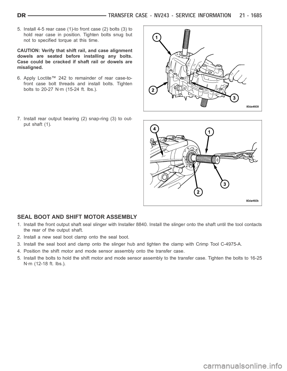
5. Install 4-5 rear case (1)-to front case (2) bolts (3) to
hold rear case in position. Tighten bolts snug but
not to specified torque at this time.
CAUTION: Verify that shift rail, and case alignment
dowels are seated before installing any bolts.
Case could be cracked if shaft rail or dowels are
misaligned.
6. Apply Loctite™ 242 to remainder of rear case-to-
front case bolt threads and install bolts. Tighten
bolts to 20-27 Nꞏm (15-24 ft. lbs.).
7. Install rear output bearing (2) snap-ring (3) to out-
put shaft (1).
SEAL BOOT AND SHIFT MOTOR ASSEMBLY
1. Install the front output shaft seal slinger with Installer 8840. Install the slinger onto the shaft until the tool contacts
the rear of the output shaft.
2. Install a new seal boot clamp onto the seal boot.
3. Install the seal boot and clamp onto the slinger hub and tighten the clampwith Crimp Tool C-4975-A.
4. Position the shift motor and mode sensor assembly onto the transfer case.
5. Install the bolts to hold the shift motor and mode sensor assembly to the transfer case. Tighten the bolts to 16-25
Nꞏm (12-18 ft. lbs.).