2006 DODGE RAM SRT-10 sensor
[x] Cancel search: sensorPage 4046 of 5267
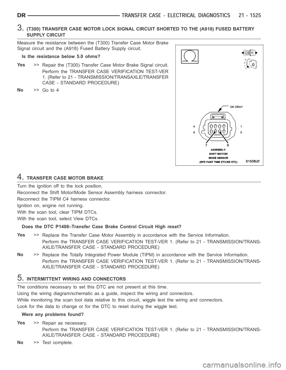
3.(T300) TRANSFER CASE MOTOR LOCK SIGNAL CIRCUIT SHORTED TO THE (A918) FUSEDBATTERY
SUPPLY CIRCUIT
Measure the resistance between the (T300) Transfer Case Motor Brake
Signal circuit and the (A918) Fused Battery Supply circuit.
Is the resistance below 5.0 ohms?
Ye s>>
Repair the (T300) Transfer Case Motor Brake Signal circuit.
Perform the TRANSFER CASE VERIFICATION TEST-VER
1. (Refer to 21 - TRANSMISSION/TRANSAXLE/TRANSFER
CASE - STANDARD PROCEDURE)
No>>
Go to 4
4.TRANSFER CASE MOTOR BRAKE
Turn the ignition off to the lock position.
Reconnect the Shift Motor/Mode Sensor Assembly harness connector.
Reconnect the TIPM C4 harness connector.
Ignition on, engine not running.
With the scan tool, clear TIPM DTCs.
With the scan tool, select View DTCs.
Does the DTC P1408–Transfer Case Brake Control Circuit High reset?
Ye s>>
Replace the Transfer Case Motor Assembly in accordance with the Service Information.
Perform the TRANSFER CASE VERIFICATION TEST-VER 1. (Refer to 21 - TRANSMISSION/TRANS-
AXLE/TRANSFER CASE - STANDARD PROCEDURE)
No>>
Replace the Totally Integrated Power Module (TIPM) in accordance with theService Information.
Perform the TRANSFER CASE VERIFICATION TEST-VER 1. (Refer to 21 - TRANSMISSION/TRANS-
AXLE/TRANSFER CASE - STANDARD PROCEDURE)
5.INTERMITTENT WIRING AND CONNECTORS
The conditions necessary to set this DTC are not present at this time.
Using the wiring diagram/schematic as a guide, inspect the wiring and connectors.
While monitoring the scan tool data relative to this circuit, wiggle test the wiring and connectors.
Look for the data to change or for the DTC to reset during the wiggle test.
Were any problems found?
Ye s>>
Repair as necessary.
Perform the TRANSFER CASE VERIFICATION TEST-VER 1. (Refer to 21 - TRANSMISSION/TRANS-
AXLE/TRANSFER CASE - STANDARD PROCEDURE)
No>>
Te s t c o m p l e t e .
Page 4048 of 5267
When Monitored:
Ignition on. Battery voltage between 9.0 and 16.0 volts.
Set Condition:
Totally Integrated Power Module (TIPM) detects low voltage on the Transfer Case Motor Control circuit for a
period of 0.5 seconds.
Possible Causes
(T101) SHIFT MOTOR CONTROL A CIRCUIT SHORTED TO GROUND
(T102) SHIFT MOTOR CONTROL B CIRCUIT SHORTED TO GROUND
(T101) SHIFT MOTOR CONTROL A CIRCUIT SHORTED TO THE (T102) SHIFT MOTOR CONTROL B CIRCUIT
SHIFT MOTOR/MODE SENSOR ASSEMBLY
TOTALLY INTEGRATED POWER MODULE (TIPM)
Diagnostic Test
1.DTC IS ACTIVE
Ignition on, engine not running.
With the scan tool, read TIPM DTCs.
Is the status Active for this DTC?
Ye s>>
Go to 2
No>>
Go to 9
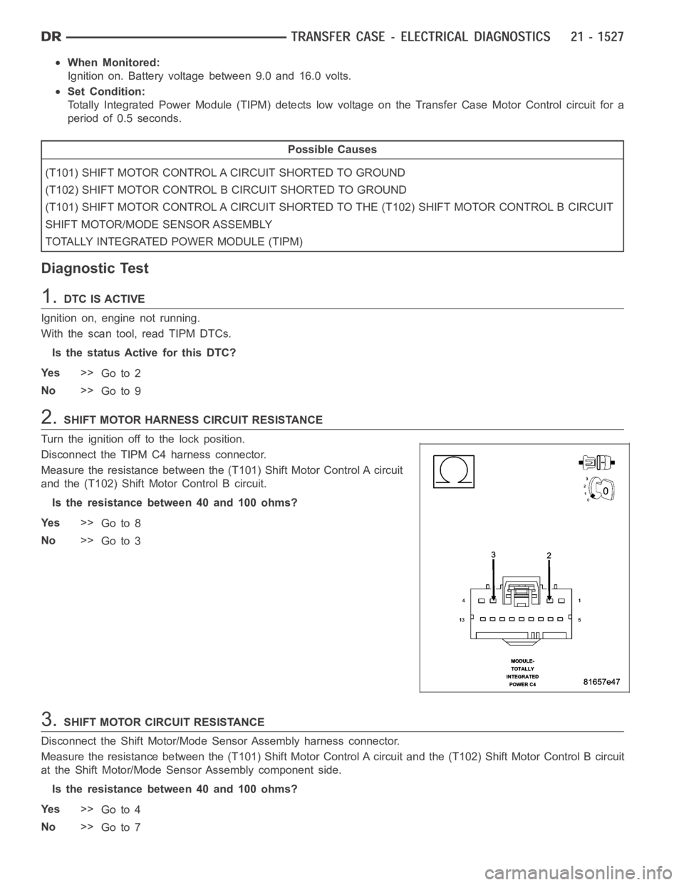
2.SHIFT MOTOR HARNESS CIRCUIT RESISTANCE
Turn the ignition off to the lock position.
Disconnect the TIPM C4 harness connector.
Measure the resistance between the (T101) Shift Motor Control A circuit
and the (T102) Shift Motor Control B circuit.
Is the resistance between 40 and 100 ohms?
Ye s>>
Go to 8
No>>
Go to 3
3.SHIFT MOTOR CIRCUIT RESISTANCE
Disconnect the Shift Motor/Mode Sensor Assembly harness connector.
Measure the resistance between the (T101) Shift Motor Control A circuit and the (T102) Shift Motor Control B circuit
at the Shift Motor/Mode Sensor Assembly component side.
Is the resistance between 40 and 100 ohms?
Ye s>>
Go to 4
No>>
Go to 7
Page 4050 of 5267
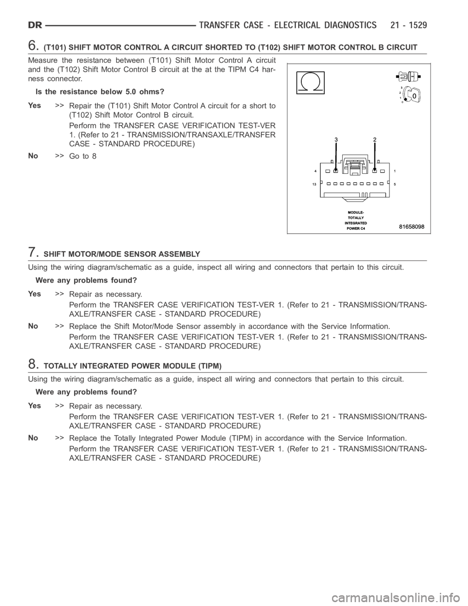
6.(T101) SHIFT MOTOR CONTROL A CIRCUIT SHORTED TO (T102) SHIFT MOTOR CONTROLB CIRCUIT
Measure the resistance between (T101) Shift Motor Control A circuit
and the (T102) Shift Motor Control B circuit at the at the TIPM C4 har-
ness connector.
Is the resistance below 5.0 ohms?
Ye s>>
Repair the (T101) Shift Motor Control A circuit for a short to
(T102) Shift Motor Control B circuit.
Perform the TRANSFER CASE VERIFICATION TEST-VER
1. (Refer to 21 - TRANSMISSION/TRANSAXLE/TRANSFER
CASE - STANDARD PROCEDURE)
No>>
Go to 8
7.SHIFT MOTOR/MODE SENSOR ASSEMBLY
Using the wiring diagram/schematic as a guide, inspect all wiring and connectors that pertain to this circuit.
Were any problems found?
Ye s>>
Repair as necessary.
Perform the TRANSFER CASE VERIFICATION TEST-VER 1. (Refer to 21 - TRANSMISSION/TRANS-
AXLE/TRANSFER CASE - STANDARD PROCEDURE)
No>>
Replace the Shift Motor/Mode Sensor assembly in accordance with the Service Information.
Perform the TRANSFER CASE VERIFICATION TEST-VER 1. (Refer to 21 - TRANSMISSION/TRANS-
AXLE/TRANSFER CASE - STANDARD PROCEDURE)
8.TOTALLY INTEGRATED POWER MODULE (TIPM)
Using the wiring diagram/schematic as a guide, inspect all wiring and connectors that pertain to this circuit.
Were any problems found?
Ye s>>
Repair as necessary.
Perform the TRANSFER CASE VERIFICATION TEST-VER 1. (Refer to 21 - TRANSMISSION/TRANS-
AXLE/TRANSFER CASE - STANDARD PROCEDURE)
No>>
Replace the Totally Integrated Power Module (TIPM) in accordance with theService Information.
Perform the TRANSFER CASE VERIFICATION TEST-VER 1. (Refer to 21 - TRANSMISSION/TRANS-
AXLE/TRANSFER CASE - STANDARD PROCEDURE)
Page 4053 of 5267
When Monitored:
Ignition on, battery voltage between 9.0 and 16.0 volts.
Set Condition:
The TIPM detects 16.0 to 18.0 volts on the Transfer Case Motor Control Circuit for 2 seconds.
Possible Causes
(T101) SHIFT MOTOR CONTROL A CIRCUIT SHORTED TO VOLTAGE
(T102) SHIFT MOTOR CONTROL BCIRCUIT SHORTED TO VOLTAGE
(T101) SHIFT MOTOR CONTROL A CIRCUIT SHORTED TO (T102) SHIFT MOTOR CONTROLB CIRCUIT
SHIFT MOTOR/MODE SENSOR ASSEMBLY
TOTALLY INTEGRATED POWER MODULE (TIPM)
Diagnostic Test
1.DTC IS ACTIVE
Ignition on, engine not running.
With the scan tool, read TIPM DTCs.
Is the status Active for this DTC?
Ye s>>
Go to 2
No>>
Go to 9
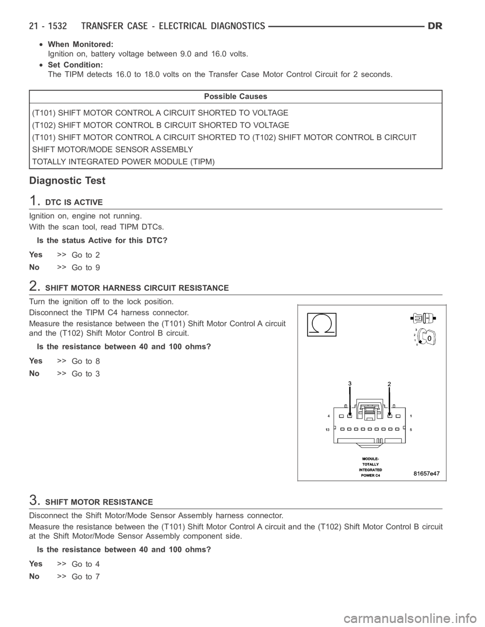
2.SHIFT MOTOR HARNESS CIRCUIT RESISTANCE
Turn the ignition off to the lock position.
Disconnect the TIPM C4 harness connector.
Measure the resistance between the (T101) Shift Motor Control A circuit
and the (T102) Shift Motor Control B circuit.
Is the resistance between 40 and 100 ohms?
Ye s>>
Go to 8
No>>
Go to 3
3.SHIFT MOTOR RESISTANCE
Disconnect the Shift Motor/Mode Sensor Assembly harness connector.
Measure the resistance between the (T101) Shift Motor Control A circuit and the (T102) Shift Motor Control B circuit
at the Shift Motor/Mode Sensor Assembly component side.
Is the resistance between 40 and 100 ohms?
Ye s>>
Go to 4
No>>
Go to 7
Page 4055 of 5267
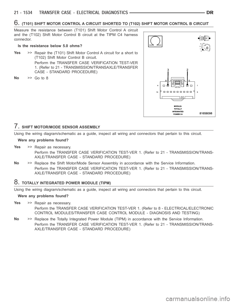
6.(T101) SHIFT MOTOR CONTROL A CIRCUIT SHORTED TO (T102) SHIFT MOTOR CONTROLB CIRCUIT
Measure the resistance between (T101) Shift Motor Control A circuit
and the (T102) Shift Motor Control B circuit at the TIPM C4 harness
connector.
Is the resistance below 5.0 ohms?
Ye s>>
Repair the (T101) Shift Motor Control A circuit for a short to
(T102) Shift Motor Control B circuit.
Perform the TRANSFER CASE VERIFICATION TEST-VER
1. (Refer to 21 - TRANSMISSION/TRANSAXLE/TRANSFER
CASE - STANDARD PROCEDURE)
No>>
Go to 8
7.SHIFT MOTOR/MODE SENSOR ASSEMBLY
Using the wiring diagram/schematic as a guide, inspect all wiring and connectors that pertain to this circuit.
Were any problems found?
Ye s>>
Repair as necessary.
Perform the TRANSFER CASE VERIFICATION TEST-VER 1. (Refer to 21 - TRANSMISSION/TRANS-
AXLE/TRANSFER CASE - STANDARD PROCEDURE)
No>>
Replace the Shift Motor/Mode Sensor Assembly in accordance with the Service Information.
Perform the TRANSFER CASE VERIFICATION TEST-VER 1. (Refer to 21 - TRANSMISSION/TRANS-
AXLE/TRANSFER CASE - STANDARD PROCEDURE)
8.TOTALLY INTEGRATED POWER MODULE (TIPM)
Using the wiring diagram/schematic as a guide, inspect all wiring and connectors that pertain to this circuit.
Were any problems found?
Ye s>>
Repair as necessary.
Perform the TRANSFER CASE VERIFICATION TEST-VER 1. (Refer to 8 - ELECTRICAL/ELECTRONIC
CONTROL MODULES/TRANSFER CASE CONTROL MODULE - DIAGNOSIS AND TESTING)
No>>
Replace the Totally Integrated Power Module (TIPM) in accordance with theService Information.
Perform the TRANSFER CASE VERIFICATION TEST-VER 1. (Refer to 21 - TRANSMISSION/TRANS-
AXLE/TRANSFER CASE - STANDARD PROCEDURE)
Page 4058 of 5267
When Monitored:
Ignition on, battery voltage between 9.0 and 16.0 volts.
Set Condition:
The TIPM detects no voltage on the Transfer Case Motor Control circuit for aperiod greater than 2 seconds,
when voltage should be present.
Possible Causes
(T101) SHIFT MOTOR CONTROL A CIRCUIT OPEN
(T102) SHIFT MOTOR CONTROL B CIRCUIT OPEN
SHIFT MOTOR/MODE SENSOR ASSEMBLY
TOTALLY INTEGRATED POWER MODULE (TIPM)
Diagnostic Test
1.DTC IS ACTIVE
Ignition on, engine not running.
With the scan tool, read TIPM DTCs.
Move the Shift control to each position, while monitoring the Data Displayon the scan tool.
Does the DTC reset?
Ye s>>
Go to 2
No>>
Go to 8
2.SHIFT MOTOR HARNESS CIRCUIT RESISTANCE
Turn the ignition off to the lock position.
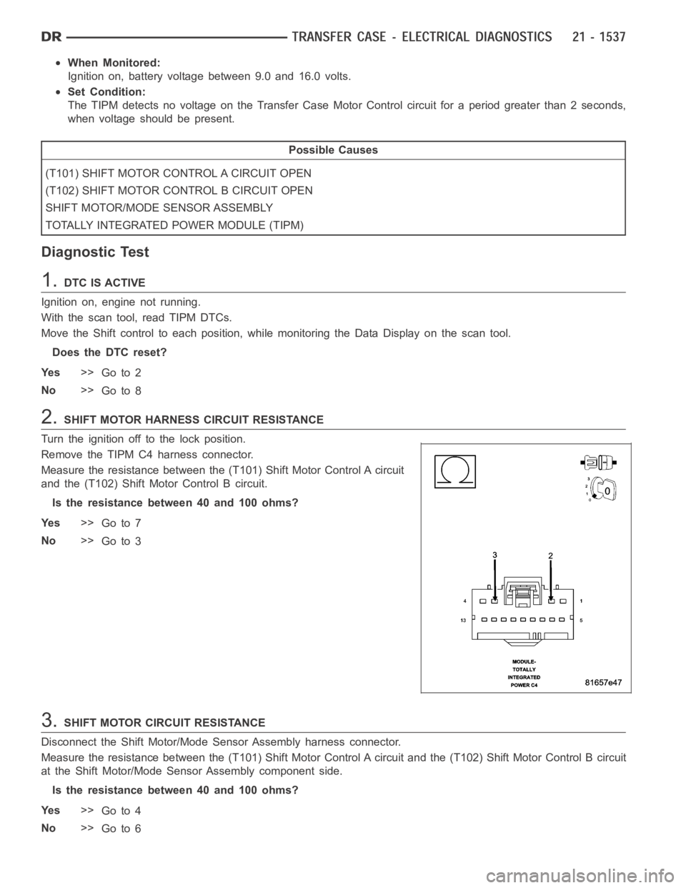
Remove the TIPM C4 harness connector.
Measure the resistance between the (T101) Shift Motor Control A circuit
and the (T102) Shift Motor Control B circuit.
Is the resistance between 40 and 100 ohms?
Ye s>>
Go to 7
No>>
Go to 3
3.SHIFT MOTOR CIRCUIT RESISTANCE
Disconnect the Shift Motor/Mode Sensor Assembly harness connector.
Measure the resistance between the (T101) Shift Motor Control A circuit and the (T102) Shift Motor Control B circuit
at the Shift Motor/Mode Sensor Assembly component side.
Is the resistance between 40 and 100 ohms?
Ye s>>
Go to 4
No>>
Go to 6
Page 4059 of 5267

4.(T101) SHIFT MOTOR CONTROL A CIRCUIT OPEN
Measure the resistance of the (T101) Shift Motor Control A circuit
between the Shift Motor/Mode Sensor Assembly harness connector and
the TIPM C4 harness connector.
Is the resistance above 5.0 ohms?
Ye s>>
Repair the (T101) Shift Motor Control A circuit for an open.
Perform the TRANSFER CASE VERIFICATION TEST-VER
1. (Refer to 21 - TRANSMISSION/TRANSAXLE/TRANSFER
CASE - STANDARD PROCEDURE)
No>>
Go to 5
5.(T102) SHIFT MOTOR CONTROL B CIRCUIT OPEN
Measure the resistance of the (T102) Shift Motor Control B circuit
between the Shift Motor/Mode Sensor Assembly harness connector and
the TIPM C4 harness connector.
Is the resistance above 5.0 ohms?
Ye s>>
Repair the (T102) Shift Motor Control B circuit for an open.
Perform the TRANSFER CASE VERIFICATION TEST-VER
1. (Refer to 21 - TRANSMISSION/TRANSAXLE/TRANSFER
CASE - STANDARD PROCEDURE)
No>>
Go to 7
6.SHIFT MOTOR/MODE SENSOR ASSEMBLY
Using the wiring diagram/schematic as a guide, inspect all wiring and connectors that pertain to this circuit.
Were any problems found?
Ye s>>
Repair as necessary.
Perform the TRANSFER CASE VERIFICATION TEST-VER 1. (Refer to 21 - TRANSMISSION/TRANS-
AXLE/TRANSFER CASE - STANDARD PROCEDURE)
No>>
Replace the Shift Motor/Mode Sensor Assembly in accordance with the Service Information.
Perform the TRANSFER CASE VERIFICATION TEST-VER 1. (Refer to 21 - TRANSMISSION/TRANS-
AXLE/TRANSFER CASE - STANDARD PROCEDURE)
Page 4087 of 5267
Condition Possible Cause Correction
Lubricant leaking from output shaft
seal or vent.1) Transfer case overfilled. 1) Drain lubricant to the correct
level.
2) Vent closed or restricted. 2) Clear or replace vent as
necessary.
3) Output shaft seals damaged or
installed incorrectly.3) Replace seal as necessary.
Check to ensure that another
component, the propeller shaft slip
yoke for example, is not causing
damage to seal.
Abnormal tire wear. 1) Extended operation on hard, dry
surfaces in the 4H position.1) Operate vehicle in the 2H
position on hard, dry surfaces.
REMOVAL
1. Raise and support vehicle.
2. Remove skid plate, if equipped. (Refer to 13 - FRAMES & BUMPERS/FRAME/TRANSFER CASE SKID PLATE
- REMOVAL)
3. Position drain oil container under transfer case.
4. Remove transfer case drain plug and drain lubricant into container.
5. Disconnect vent hose and transfer case position sensor connector.
6. Disconnect shift rod from grommet in transfer case shift lever, or from floor shift arm whichever provides easy
access. Use channel lock style pliers to press rod out of lever grommet.
7. Support transmission with jack stand.
8. Mark front and rear propeller shafts for assembly reference.
9. Remove front and rear propeller shafts. (Refer to 3 - DIFFERENTIAL & DRIVELINE/PROPELLER SHAFT/PRO-
PELLER SHAFT - REMOVAL)
10. Support transfer case with suitable jack. Secure transfer case to jackwith safety chains.
11. Remove nuts attaching transfer case to transmission.
12. Move transfer case assembly rearward until free of transmission outputshaft.
13. Lower jack and move transfer case from under vehicle.
DISASSEMBLY
Position transfer case in a shallow drain pan. Remove drain plug and drain any remaining lubricant remaining in
case.
SHIFT LEVER AND FRONT OUTPUT SHAFT SEAL
1. Shift transfer case into NEUTRAL.
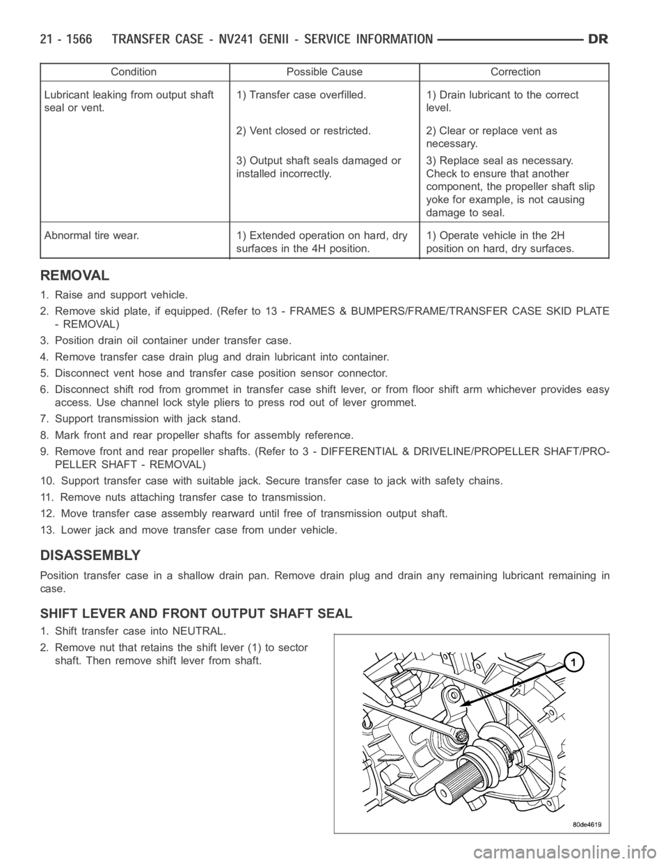
2. Remove nut that retains the shift lever (1) to sector
shaft. Then remove shift lever from shaft.