2006 DODGE RAM SRT-10 sensor
[x] Cancel search: sensorPage 4006 of 5267

4. Remove timing valve cover.
5. Remove 3-4 timing valve and spring.
6. Remove 3-4 quick fill valve, spring and plug.
7. Remove 3-4 shift valve and spring.
8. Remove converter clutch valve, spring and plug.
9. Remove converter clutch timing valve, retainer and
valve spring.
CLEANING
Clean the valve housings, valves, plugs, springs, and separator plates with a standard parts cleaning solution only.
Do not use gasoline, kerosene, or any type of caustic solution.
Do not immerse any of the electrical components in cleaning solution. Clean the governor solenoid and sensor and
the dual solenoid and harness assembly by wiping them off with dry shop towels only.
Dry all except the electrical parts with compressed air. Make sure all passages are clean and free from obstructions.
Do not use rags or shop towels to dry or wipe off valve body components. Lint from these materials can
stick to valve body parts, interfere with valve operation, and clog filters and fluid passages.
Wipe the governor pressure sensor and solenoid valve with dry, lint free shop towels only. The O-rings on the sen-
sor and solenoid valve are the only serviceable components. Be sure the vent ports in the solenoid valve are open
and not blocked by dirt or debris. Replace the valve and/or sensor only whenDRB scan tool diagnosis indicates this
is necessary. Or, if either part has sustained physical damage (dented, deformed, broken, etc.).
CAUTION: Do not turn the small screw at the end of the solenoid valve for any reason. Turning the screw
in either direction will ruin solenoid calibration and result in solenoidfailure. In addition, the filter on the
solenoid valve is NOT serviceable. Do not try to remove the filter as this will damage the valve housing.
INSPECTION
Inspect the throttle and manual valve levers and shafts. Do not attempt to straighten a bent shaft or correct a loose
lever. Replace these components if worn, bent, loose or damaged in any way.
Inspect all of the valve body mating surfaces for scratches, nicks, burrs,or distortion. Use a straightedge to check
surface flatness. Minor scratches may be removed with crocus cloth using only very light pressure.
Minor distortion of a valve body mating surface may be corrected by smoothing the surface with a sheet of crocus
cloth. Position the crocus cloth on a surface plate, sheet of plate glass orequally flat surface. If distortion is severe
or any surfaces are heavily scored, the valve body will have to be replaced.
CAUTION: Many of the valves and plugs, such as the throttle valve, shuttle valve plug, 1-2 shift valve and
1-2 governor plug, are made of coated aluminum. Aluminum components are identified by the dark color of
thespecialcoatingappliedtothesurface(orbytestingwithamagnet).Donot sand aluminum valves or
plugs under any circumstances. This practice could damage the special coating causing the valves/plugs to
stick and bind.
Inspect the valves and plugs for scratches, burrs, nicks, or scores. Minorsurface scratches on steel valves and
plugs can be removed with crocus cloth butdo not round off the edges of the valve or plug lands.Maintaining
Page 4007 of 5267
sharpness of these edges is vitally important. The edges prevent foreign matter from lodging between the valves
and plugs and the bore.
Inspect all the valve and plug bores in the valve body. Use a penlight to viewthe bore interiors. Replace the valve
body if any bores are distorted or scored. Inspect all of the valve body springs. The springs must be free of dis-
tortion, warpage or broken coils.
Check the two separator plates for distortion or damage of any kind. Inspect the upper housing, lower housing, 3-4
accumulator housing, and transfer plate carefully. Be sure all fluid passages are clean and clear. Check condition of
the upper housing and transfer plate check balls as well. The check balls and ball seats must not be worn or dam-
aged.
Trial fit each valve and plug in its bore to check freedom of operation. Whenclean and dry, the valves and plugs
shoulddropfreelyintothebores.
Valve body bores do not change dimensionally with use. If the valve body functioned correctly when new, it will
continue to operate properly after cleaning and inspection. It should notbe necessary to replace a valve body
assembly unless it is damaged in handling.
The only serviceable valve body components are listed below. The remaining valve body components are serviced
only as part of a complete valve body assembly. Serviceable parts are:
dual solenoid and harness assembly
solenoid gasket
solenoid case connector O-rings and shoulder bolt
switch valve and spring
pressure adjusting screw and bracket assembly
throttle lever
manual lever and shaft seal
throttle lever shaft seal, washer, and E-clip
fluid filter and screws
detent ball and spring
valve body screws
governor pressure solenoid
governor pressure sensor and retaining clip
park lock rod and E-clip
ASSEMBLY
CAUTION: Do not force valves or plugs into place during reassembly. If the valve body bores, valves and
plugs are free of distortion or burrs, the valve body components should allslide into place easily. In addi-
tion, do not overtighten the transfer plate and valve body screws during reassembly. Overtightening can
distort the housings resulting in valve sticking, cross leakage and unsatisfactory operation. Tighten valve
body screws to recommended torque only.
Page 4017 of 5267
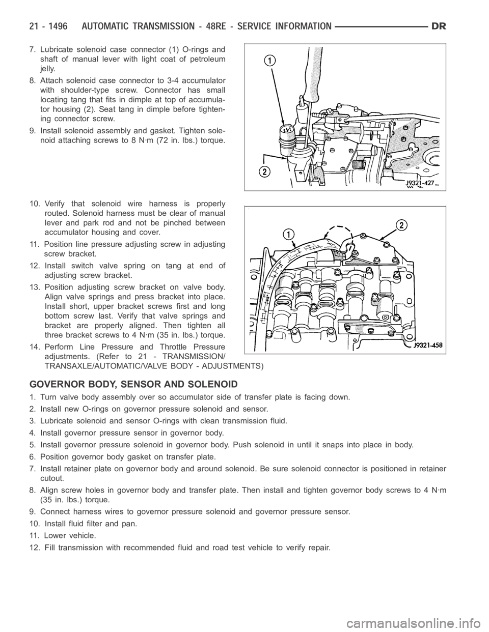
7. Lubricate solenoid case connector (1) O-rings and
shaft of manual lever with light coat of petroleum
jelly.
8. Attach solenoid case connector to 3-4 accumulator
with shoulder-type screw. Connector has small
locating tang that fits indimple at top of accumula-
tor housing (2). Seat tang in dimple before tighten-
ing connector screw.
9. Install solenoid assembly and gasket. Tighten sole-
noid attaching screws to 8 Nꞏm (72 in. lbs.) torque.
10. Verify that solenoid wire harness is properly
routed. Solenoid harness must be clear of manual
lever and park rod and not be pinched between
accumulator housing and cover.
11. Position line pressure adjusting screw in adjusting
screw bracket.
12. Install switch valve spring on tang at end of
adjusting screw bracket.
13. Position adjusting screw bracket on valve body.
Align valve springs and press bracket into place.
Install short, upper bracket screws first and long
bottom screw last. Verify that valve springs and
bracket are properly aligned. Then tighten all
three bracket screws to 4 Nꞏm (35 in. lbs.) torque.
14. Perform Line Pressure and Throttle Pressure
adjustments. (Refer to 21 - TRANSMISSION/
TRANSAXLE/AUTOMATIC/VALVE BODY - ADJUSTMENTS)
GOVERNOR BODY, SENSOR AND SOLENOID
1. Turn valve body assembly over so accumulator side of transfer plate is facing down.
2. Install new O-rings on governor pressure solenoid and sensor.
3. Lubricate solenoid and sensor O-rings with clean transmission fluid.
4. Install governor pressure sensor in governor body.
5. Install governor pressure solenoid in governor body. Push solenoid in until it snaps into place in body.
6. Position governor body gasket on transfer plate.
7. Install retainer plate on governor body and around solenoid. Be sure solenoid connector is positioned in retainer
cutout.
8. Align screw holes in governor body and transfer plate. Then install and tighten governor body screws to 4 Nꞏm
(35 in. lbs.) torque.
9. Connect harness wires to governor pressure solenoid and governor pressure sensor.
10. Install fluid filter and pan.
11. Lower vehicle.
12. Fill transmission with recommended fluid and road test vehicle to verify repair.
Page 4018 of 5267
INSTALLATION
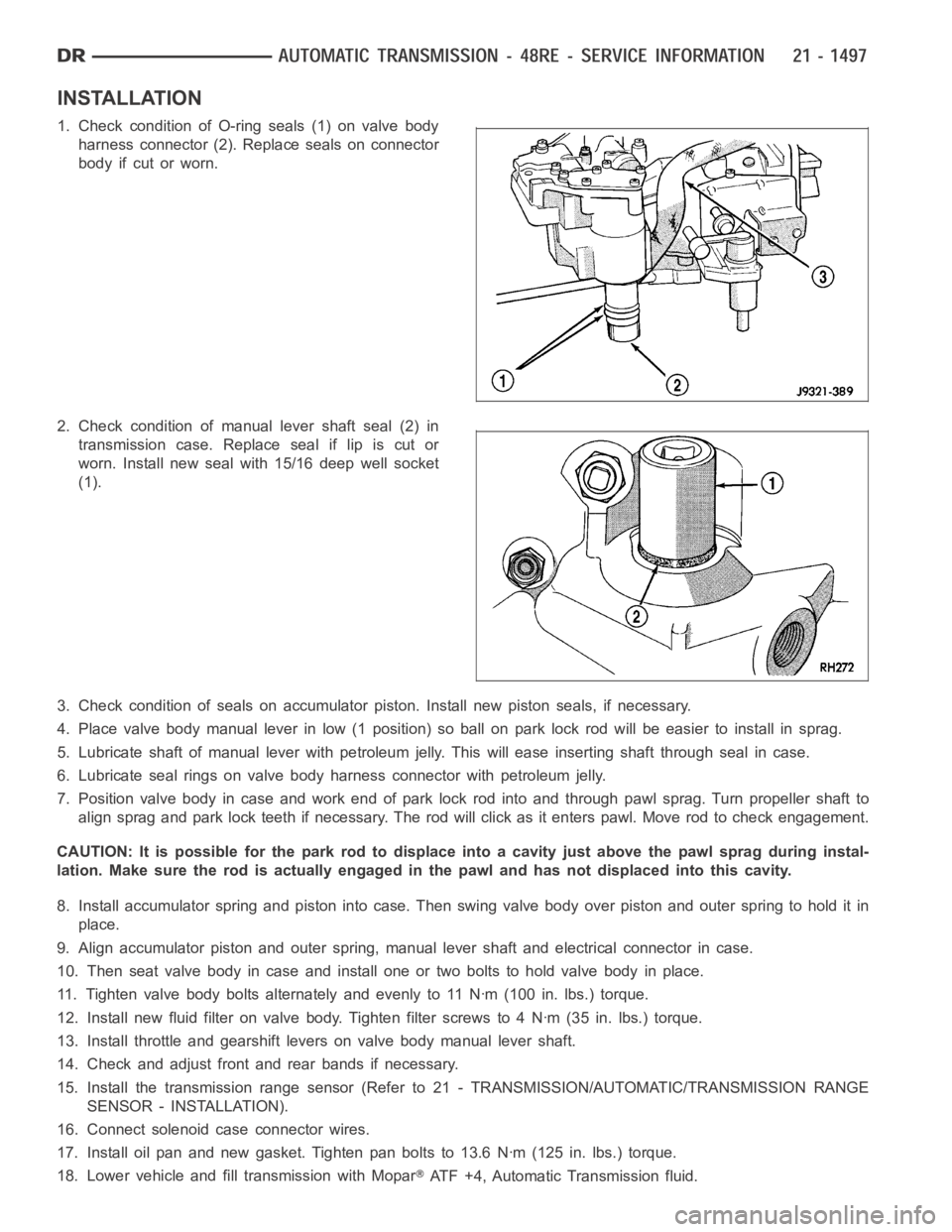
1. Check condition of O-ring seals (1) on valve body
harness connector (2). Replace seals on connector
body if cut or worn.
2. Check condition of manual lever shaft seal (2) in
transmission case. Replace seal if lip is cut or
worn. Install new seal with 15/16 deep well socket
(1).
3. Check condition of seals on accumulator piston. Install new piston seals, if necessary.
4. Place valve body manual lever in low (1 position) so ball on park lock rod will be easier to install in sprag.
5. Lubricate shaft of manual lever with petroleum jelly. This will ease inserting shaft through seal in case.
6. Lubricate seal rings on valve body harness connector with petroleum jelly.
7. Position valve body in case and work end of park lock rod into and through pawl sprag. Turn propeller shaft to
align sprag and park lock teeth if necessary. The rod will click as it enterspawl. Move rod to check engagement.
CAUTION: It is possible for the park rod to displace into a cavity just abovethe pawl sprag during instal-
lation. Make sure the rod is actually engaged in the pawl and has not displaced into this cavity.
8. Install accumulator spring and piston into case. Then swing valve body overpistonandouterspringtoholditin
place.
9. Align accumulator piston and outer spring, manual lever shaft and electrical connector in case.
10. Then seat valve body in case and install one or two bolts to hold valve bodyinplace.
11. Tighten valve body bolts alternately and evenly to 11 Nꞏm (100 in. lbs.)torque.
12. Install new fluid filter on valve body. Tighten filter screws to 4 Nꞏm (35 in. lbs.) torque.
13. Install throttle and gearshift levers on valve body manual lever shaft.
14. Check and adjust front and rear bands if necessary.
15. Install the transmission range sensor (Refer to 21 - TRANSMISSION/AUTOMATIC/TRANSMISSION RANGE
SENSOR - INSTALLATION).
16. Connect solenoid case connector wires.
17. Install oil pan and new gasket. Tighten pan bolts to 13.6 Nꞏm (125 in. lbs.) torque.
18. Lower vehicle and fill transmission with Mopar
ATF +4, Automatic Transmission fluid.
Page 4020 of 5267
page page
TRANSFER CASE - ELECTRICAL
DIAGNOSTICS
DIAGNOSIS AND TESTING
C1401- TRANSFER CASE RANGE SELECT
SWITCH CIRCUIT LOW. .................. 1501
C1402- TRANSFER CASE RANGE SELECT
SWITCH CIRCUIT HIGH................... 1506
C1404- TRANSFER CASE RANGE
POSITION SENSOR CIRCUIT LOW......... 1511
C1405- TRANSFER CASE RANGE
POSITION SENSOR CIRCUIT HIGH........ 1515
C1407- TRANSFER CASE BRAKE
CONTROL CIRCUIT LOW.................. 1520
C1408-TRANSFER CASE BRAKE CONTROL
CIRCUIT HIGH............................ 1523
C140B- TRANSFER CASE MOTOR
CONTROL CIRCUIT LOW.................. 1526C140C - TRANSFER CASE MOTOR
CONTROL CIRCUIT HIGH................. 1531
C140D - TRANSFER CASE MOTOR
CONTROL CIRCUIT OPEN................. 1536
C1464-FRONT AXLE DISCONNECT
CONTROL CIRCUIT LOW.................. 1540
C1465-FRONT AXLE DISCONNECT
CONTROL CIRCUIT HIGH................. 1544
C1468-FRONT AXLE DISCONNECT
RETURN CONTROL CIRCUIT LOW......... 1548
C1469-FRONT AXLE DISCONNECT
RETURN CONTROL CIRCUIT HIGH........ 1553
C146A–FRONT AXLE DISCONNECT
RETURN CONTROL CIRCUIT OPEN........ 1557
STANDARD PROCEDURE
TRANSFER CASE VERIFICATION TEST .... 1562
Page 4032 of 5267

C1404- TRANSFER CASE RANGE POSITION SENSOR CIRCUIT LOW
For a complete wiring diagramRefer to Section 8W
Page 4033 of 5267
When Monitored:
Ignition on. Battery voltage between 9.0 and 16.0 volts.
Set Condition:
The TIPM detects a short to ground on the Transfer Case Position Sensor Signal circuit for 2.0 seconds.
Possible Causes
(T103) 5 VOLT SUPPLY CIRCUIT OPEN
(T103) 5 VOLT SUPPLY CIRCUIT SHORTED TO GROUND
(D201) MODE SENSOR A CIRCUIT SHORTED TO GROUND
(D201) MODE SENSOR A CIRCUIT SHORTED TO (G180) SENSOR RETURN CIRCUIT
SHIFT MOTOR/MODE SENSOR ASSEMBLY
TOTALLY INTERGRATED POWER MODULE (TIPM)
Diagnostic Test
1.T-CASE POSITION SENSOR VOLTAGE BELOW 0.2 VOLTS
Ignition on, engine not running.
With the scan tool under TIPM, read the T-Case Position Sensor voltage.
Is the voltage below 0.2 volts?
Ye s>>
Go to 2
No>>
Go to 8
2.(T103) 5 VOLT SUPPLY CIRCUIT VOLTAGE BELOW 0.2 VOLTS
Turn the ignition off to the lock position.
Disconnect the Shift Motor/Mode Sensor harness connector.
Ignition on, engine not running.
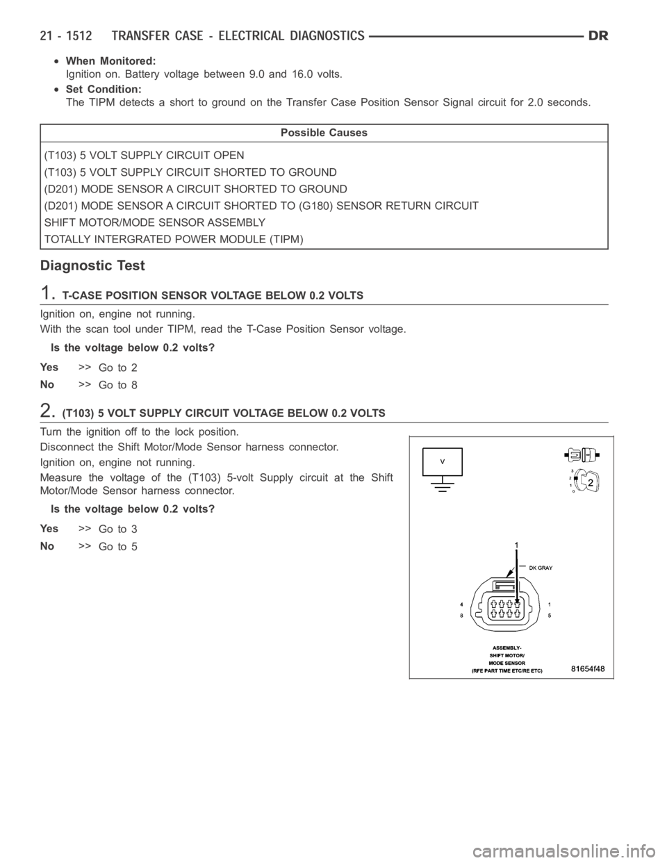
Measure the voltage of the (T103) 5-volt Supply circuit at the Shift
Motor/Mode Sensor harness connector.
Is the voltage below 0.2 volts?
Ye s>>
Go to 3
No>>
Go to 5
Page 4034 of 5267
3.(T103) 5-VOLT SUPPLY CIRCUIT OPEN
Turn the ignition off to the lock position.
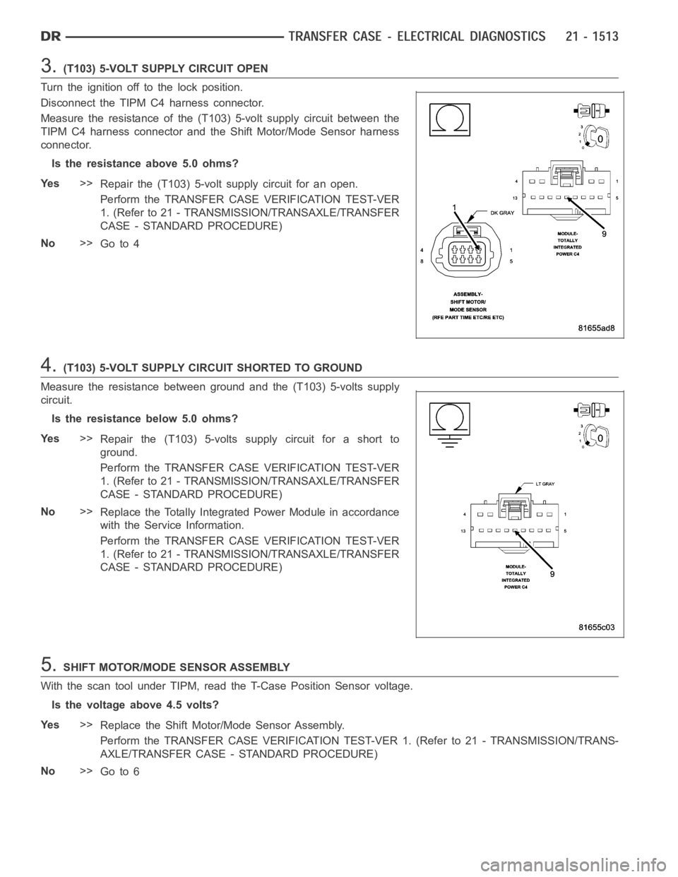
Disconnect the TIPM C4 harness connector.
Measure the resistance of the (T103) 5-volt supply circuit between the
TIPM C4 harness connector and the Shift Motor/Mode Sensor harness
connector.
Is the resistance above 5.0 ohms?
Ye s>>
Repair the (T103) 5-volt supply circuit for an open.
Perform the TRANSFER CASE VERIFICATION TEST-VER
1. (Refer to 21 - TRANSMISSION/TRANSAXLE/TRANSFER
CASE - STANDARD PROCEDURE)
No>>
Go to 4
4.(T103) 5-VOLT SUPPLY CIRCUIT SHORTED TO GROUND
Measure the resistance between ground and the (T103) 5-volts supply
circuit.
Is the resistance below 5.0 ohms?
Ye s>>
Repair the (T103) 5-volts supply circuit for a short to
ground.
Perform the TRANSFER CASE VERIFICATION TEST-VER
1. (Refer to 21 - TRANSMISSION/TRANSAXLE/TRANSFER
CASE - STANDARD PROCEDURE)
No>>
Replace the Totally Integrated Power Module in accordance
with the Service Information.
Perform the TRANSFER CASE VERIFICATION TEST-VER
1. (Refer to 21 - TRANSMISSION/TRANSAXLE/TRANSFER
CASE - STANDARD PROCEDURE)
5.SHIFT MOTOR/MODE SENSOR ASSEMBLY
With the scan tool under TIPM, read the T-Case Position Sensor voltage.
Is the voltage above 4.5 volts?
Ye s>>
Replace the Shift Motor/Mode Sensor Assembly.
Perform the TRANSFER CASE VERIFICATION TEST-VER 1. (Refer to 21 - TRANSMISSION/TRANS-
AXLE/TRANSFER CASE - STANDARD PROCEDURE)
No>>
Go to 6