Page 3871 of 5267
6. Pull solenoid (1) from governor body (3).
7. Pull pressure sensor from governor body.
8. Remove bolts holding governor body to valve body.
9. Separate governor body (1) from valve body.
10. Remove governor body gasket.
INSTALLATION
Before installing the pressure sensor and solenoid in
the governor body, replace o-ring seals, clean the gas-
ket surfaces and replace gasket.
1. Place gasket (2) in position on back of governor
body (1).
2. Place governor body in position on valve body.
3. Install bolts to hold governor body to valve body.
Page 3872 of 5267
4. Lubricate o-ring on pressure sensor with transmis-
sion fluid.
5. Align pressure sensor to bore in governor body.
6. Push pressure sensor into governor body.
7. Lubricate o-ring (2), on pressure solenoid (1), with
transmission fluid.
8. Align pressure solenoid (1) to bore in governor
body (3).
9. Push solenoid into governor body.
10. Place solenoid retainer (1) in position on governor
(2).
11. Install screws to hold pressure solenoid retainer to
governor body.
12. Engage wire connectors into pressure sensor (1)
and solenoid (2).
13. Install transmission fluid pan and (new) filter.
14. Lower vehicle and road test to verify repair.
Page 3876 of 5267
PROCEDURE TWO
1. Start engine and apply parking brake.
2. Shift the transmission into DRIVE for approximately 2 seconds.
3. Shift the transmission into REVERSE for approximately 2 seconds.
4. Shift the transmission into PARK.
5. Hook up DRB
scan tool and select engine.
6. Select sensors.
7. Read the transmission temperature value.
8. Compare the fluid temperature value with the chart.
9. Adjust transmission fluid level shown on the dipstick according to the chart.
NOTE: After adding any fluid to the transmission, wait a minimum of 2 minutes for the oil to fully drain from
the fill tube into the transmission before rechecking the fluid level.
10. Check transmission for leaks.
FLUID AND FILTER REPLACEMENT
For proper service intervals (Refer to LUBRICATION & MAINTENANCE/MAINTENANCE SCHEDULES - DESCRIP-
TION). The service fluid fill after a filter change is approximately 3.8 liters (4.0 quarts).
Page 3888 of 5267

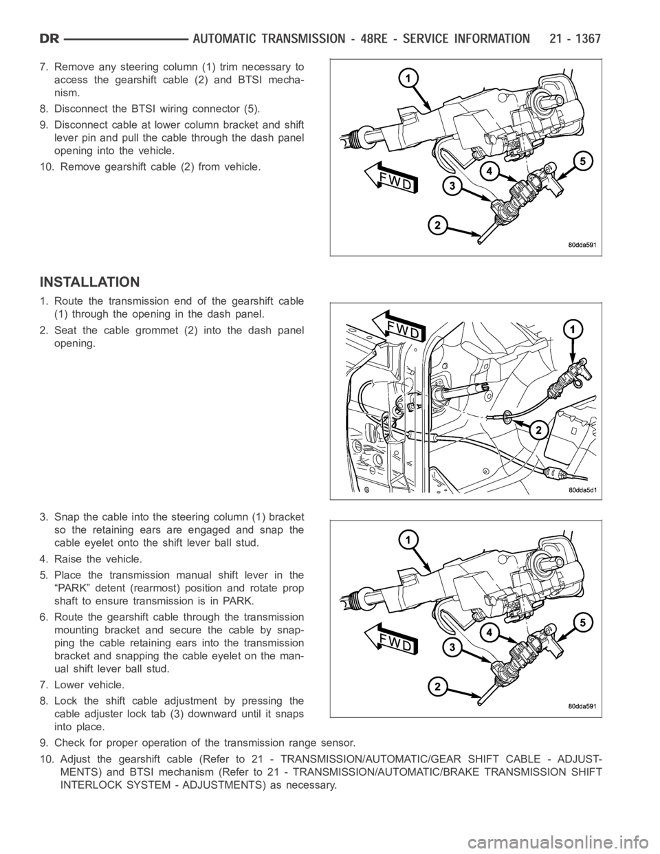
7. Remove any steering column (1) trim necessary to
access the gearshift cable (2) and BTSI mecha-
nism.
8. Disconnect the BTSI wiring connector (5).
9. Disconnect cable at lower column bracket and shift
lever pin and pull the cable through the dash panel
opening into the vehicle.
10. Remove gearshift cable (2) from vehicle.
INSTALLATION
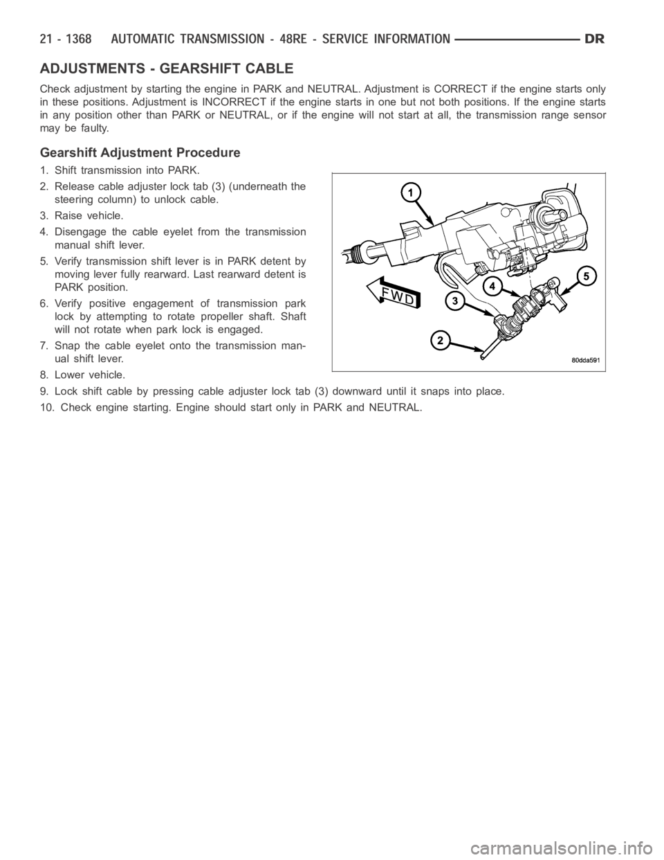
1. Route the transmission end of the gearshift cable
(1) through the opening in the dash panel.
2. Seat the cable grommet (2) into the dash panel
opening.
3. Snap the cable into the steering column (1) bracket
so the retaining ears are engaged and snap the
cable eyelet onto the shift lever ball stud.
4. Raise the vehicle.
5. Place the transmission manual shift lever in the
“PARK” detent (rearmost) position and rotate prop
shaft to ensure transmission is in PARK.
6. Route the gearshift cable through the transmission
mounting bracket and secure the cable by snap-
ping the cable retaining ears into the transmission
bracket and snapping the cable eyelet on the man-
ual shift lever ball stud.
7. Lower vehicle.
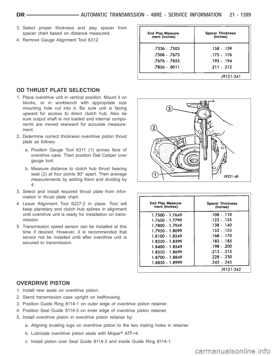
8. Lock the shift cable adjustment by pressing the
cable adjuster lock tab (3) downward until it snaps
into place.
9. Check for proper operation of the transmission range sensor.
10. Adjust the gearshift cable (Refer to 21 - TRANSMISSION/AUTOMATIC/GEAR SHIFT CABLE - ADJUST-
MENTS) and BTSI mechanism (Refer to 21 - TRANSMISSION/AUTOMATIC/BRAKE TRANSMISSION SHIFT
INTERLOCK SYSTEM - ADJUSTMENTS) as necessary.
Page 3889 of 5267

ADJUSTMENTS - GEARSHIFT CABLE
Check adjustment by starting the engine in PARK and NEUTRAL. Adjustment isCORRECT if the engine starts only
in these positions. Adjustment is INCORRECT if the engine starts in one butnot both positions. If the engine starts
in any position other than PARK or NEUTRAL, or if the engine will not start atall, the transmission range sensor
may be faulty.
Gearshift Adjustment Procedure
1. Shift transmission into PARK.
2. Release cable adjuster lock tab (3) (underneath the
steering column) to unlock cable.
3. Raise vehicle.
4. Disengage the cable eyelet from the transmission
manual shift lever.
5. Verify transmission shift lever is in PARK detent by
moving lever fully rearward. Last rearward detent is
PARK position.
6. Verify positive engagement of transmission park
lock by attempting to rotate propeller shaft. Shaft
will not rotate when park lock is engaged.
7. Snap the cable eyelet onto the transmission man-
ual shift lever.
8. Lower vehicle.
9. Lock shift cable by pressing cable adjuster lock tab (3) downward until it snaps into place.
10. Check engine starting. Engine should start only in PARK and NEUTRAL.
Page 3900 of 5267
DISASSEMBLY
1. Remove transmission speed sensor (2) and o-ring
seal (3) from overdrive case.
2. Remove overdrive piston thrust bearing (1).
Page 3920 of 5267

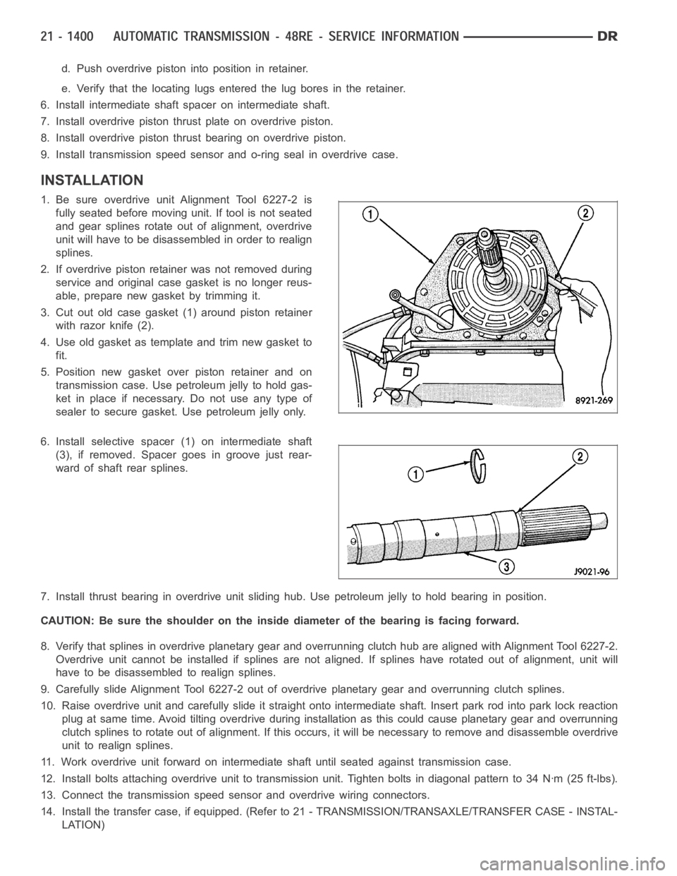
3. Select proper thickness end play spacer from
spacer chart based on distance measured.
4. Remove Gauge Alignment Tool 6312.
OD THRUST PLATE SELECTION
1. Place overdrive unit in vertical position. Mount it on
blocks, or in workbench with appropriate size
mounting hole cut into it. Be sure unit is facing
upward for access to direct clutch hub. Also be
sure output shaft is not loaded and internal compo-
nents are moved rearward for accurate measure-
ment.
2. Determine correct thickness overdrive piston thrust
plate as follows:
a. Position Gauge Tool 6311 (1) across face of
overdrive case. Then position Dial Caliper over
gauge tool.
b. Measure distance to clutch hub thrust bearing
seat (2) at four points 90° apart. Then average
measurements by adding them and dividing by
4.
3. Select and install required thrust plate from infor-
mation in thrust plate chart.
4. Leave Alignment Tool 6227-2 in place. Tool will
keep planetary and clutch hub splines in alignment
until overdrive unit is ready for installation on trans-
mission.
5. Transmission speed sensor can be installed at this
time if desired. However, it is recommended that
sensor not be installed until after overdrive unit is
secured to transmission.
OVERDRIVE PISTON
1. Install new seals on overdrive piston.
2. Stand transmission case upright on bellhousing.
3. Position Guide Ring 8114-1 on outer edge of overdrive piston retainer.
4. Position Seal Guide 8114-3 on inner edge of overdrive piston retainer.
5. Install overdrive piston in overdrive piston retainer by:
a. Aligning locating lugs on overdrive piston to the two mating holes in retainer.
b. Lubricate overdrive piston seals with Mopar
ATF+4.
c. Install piston over Seal Guide 8114-3 and inside Guide Ring 8114-1.
Page 3921 of 5267

d. Push overdrive piston into position in retainer.
e. Verify that the locating lugs entered the lug bores in the retainer.
6. Install intermediate shaft spacer on intermediate shaft.
7. Install overdrive piston thrust plate on overdrive piston.
8. Install overdrive piston thrust bearing on overdrive piston.
9. Install transmission speed sensorand o-ring seal in overdrive case.
INSTALLATION
1. Be sure overdrive unit Alignment Tool 6227-2 is
fully seated before moving unit. If tool is not seated
and gear splines rotate out of alignment, overdrive
unit will have to be disassembled in order to realign
splines.
2. If overdrive piston retainer was not removed during
service and original case gasket is no longer reus-
able, prepare new gasket by trimming it.
3. Cut out old case gasket (1) around piston retainer
with razor knife (2).
4. Use old gasket as template and trim new gasket to
fit.
5. Position new gasket over piston retainer and on
transmission case. Use petroleum jelly to hold gas-
ket in place if necessary. Do not use any type of
sealer to secure gasket. Use petroleum jelly only.
6. Install selective spacer (1) on intermediate shaft
(3), if removed. Spacer goes in groove just rear-
ward of shaft rear splines.
7. Install thrust bearing in overdrive unit sliding hub. Use petroleum jelly to hold bearing in position.
CAUTION: Be sure the shoulder on the inside diameter of the bearing is facingforward.
8. Verify that splines in overdrive planetary gear and overrunning clutchhub are aligned with Alignment Tool 6227-2.
Overdrive unit cannot be installed if splines are not aligned. If splines have rotated out of alignment, unit will
have to be disassembled to realign splines.
9. Carefully slide Alignment Tool 6227-2 out of overdrive planetary gear and overrunning clutch splines.
10. Raise overdrive unit and carefully slide it straight onto intermediate shaft. Insert park rod into park lock reaction
plug at same time. Avoid tilting overdrive during installation as this could cause planetary gear and overrunning
clutch splines to rotate out of alignment. If this occurs, it will be necessary to remove and disassemble overdrive
unit to realign splines.
11. Work overdrive unit forward on intermediate shaft until seated against transmission case.
12. Install bolts attaching overdrive unit to transmission unit. Tightenbolts in diagonal pattern to 34 Nꞏm (25 ft-lbs).
13. Connect the transmission speed sensor and overdrive wiring connectors.
14. Install the transfer case, if equipped. (Refer to 21 - TRANSMISSION/TRANSAXLE/TRANSFER CASE - INSTAL-
LATION)