Page 3944 of 5267
SENSOR-SPEED
DESCRIPTION
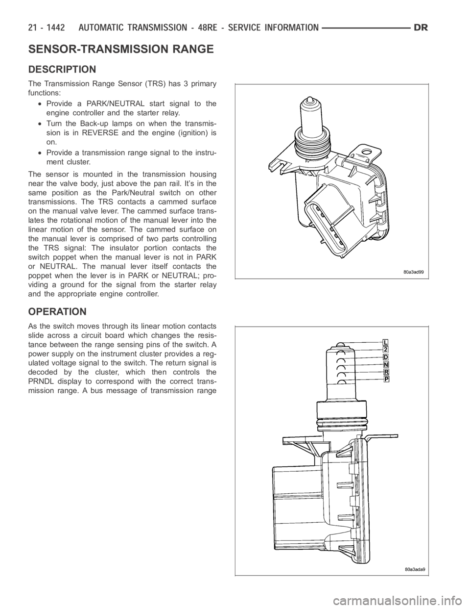
The speed sensor (1) is located in the overdrive gear
case. The sensor is positioned over the park gear and
monitors transmission output shaft rotating speed.
OPERATION
Speed sensor signals are triggered by the park gear lugs as they rotate pastthe sensor pickup face. Input signals
from the sensor are sent to the transmission control module for processing. Signals from this sensor are shared with
the powertrain control module.
Page 3963 of 5267

SENSOR-TRANSMISSION RANGE
DESCRIPTION
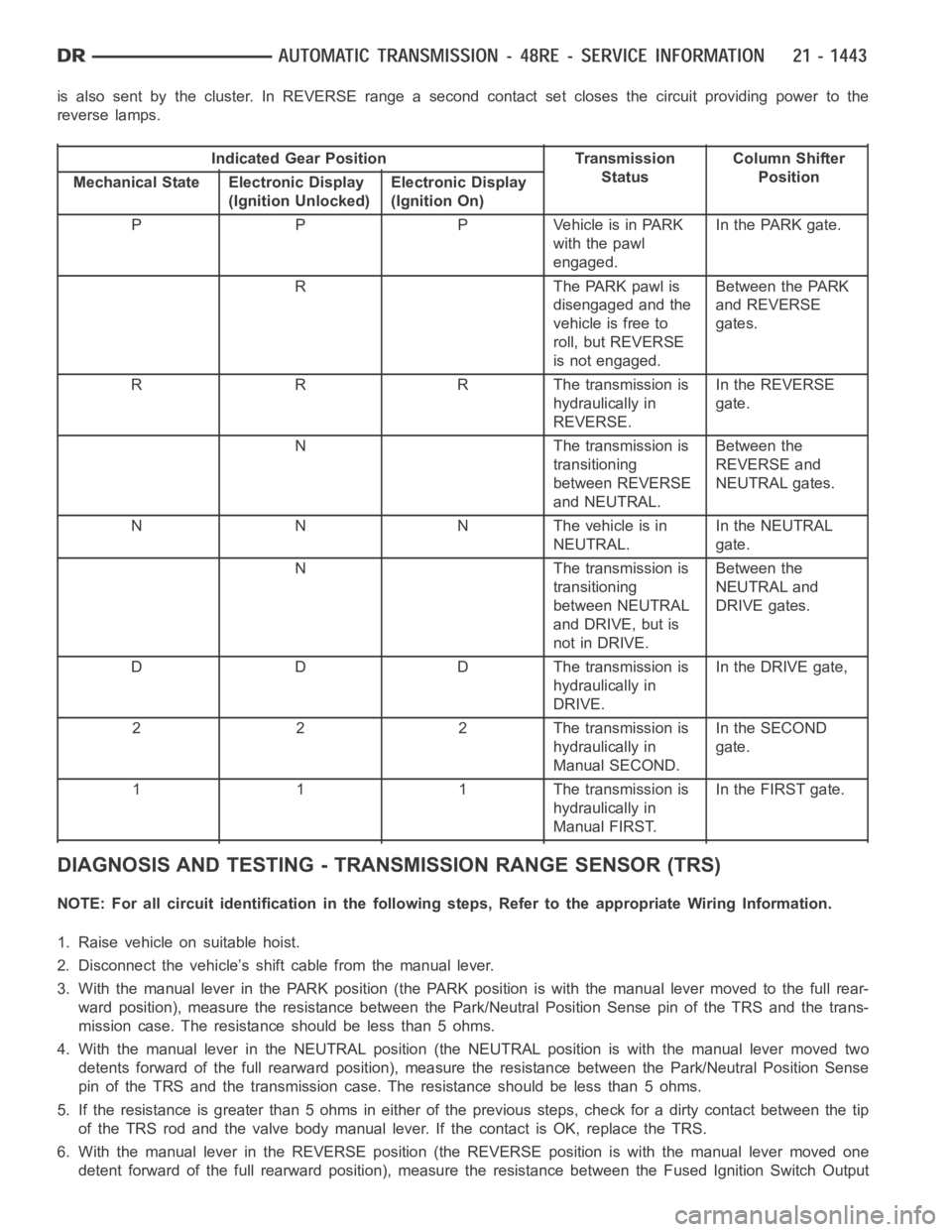
The Transmission Range Sensor (TRS) has 3 primary
functions:
Provide a PARK/NEUTRAL start signal to the
engine controller and the starter relay.
Turn the Back-up lamps on when the transmis-
sion is in REVERSE and the engine (ignition) is
on.
Provide a transmission range signal to the instru-
ment cluster.
The sensor is mounted in the transmission housing
near the valve body, just above the pan rail. It’s in the
same position as the Park/Neutral switch on other
transmissions. The TRS contacts a cammed surface
on the manual valve lever. The cammed surface trans-
lates the rotational motion of the manual lever into the
linear motion of the sensor. The cammed surface on
the manual lever is comprised of two parts controlling
the TRS signal: The insulator portion contacts the
switch poppet when the manual lever is not in PARK
or NEUTRAL. The manual lever itself contacts the
poppet when the lever is in PARK or NEUTRAL; pro-
viding a ground for the signal from the starter relay
and the appropriate engine controller.
OPERATION
As the switch moves through its linear motion contacts
slide across a circuit board which changes the resis-
tance between the range sensing pins of the switch. A
power supply on the instrument cluster provides a reg-
ulated voltage signal to the switch. The return signal is
decoded by the cluster, which then controls the
PRNDL display to correspond with the correct trans-
mission range. A bus message of transmission range
Page 3964 of 5267

is also sent by the cluster. In REVERSE range a second contact set closes thecircuit providing power to the
reverse lamps.
Indicated Gear Position Transmission
StatusColumn Shifter
Position
Mechanical State Electronic Display
(Ignition Unlocked)Electronic Display
(Ignition On)
P P P Vehicle is in PARK
with the pawl
engaged.In the PARK gate.
R The PARK pawl is
disengaged and the
vehicle is free to
roll, but REVERSE
is not engaged.Between the PARK
and REVERSE
gates.
R R R The transmission is
hydraulically in
REVERSE.In the REVERSE
gate.
N The transmission is
transitioning
between REVERSE
and NEUTRAL.Between the
REVERSE and
NEUTRAL gates.
N N N The vehicle is in
NEUTRAL.In the NEUTRAL
gate.
N The transmission is
transitioning
between NEUTRAL
and DRIVE, but is
not in DRIVE.Between the
NEUTRAL and
DRIVE gates.
D D D The transmission is
hydraulically in
DRIVE.In the DRIVE gate,
2 2 2 The transmission is
hydraulically in
Manual SECOND.In the SECOND
gate.
1 1 1 The transmission is
hydraulically in
Manual FIRST.In the FIRST gate.
DIAGNOSIS AND TESTING - TRANSMISSION RANGE SENSOR (TRS)
NOTE: For all circuit identification in the following steps, Refer to the appropriate Wiring Information.
1. Raise vehicle on suitable hoist.
2. Disconnect the vehicle’s shift cable from the manual lever.
3. With the manual lever in the PARK position (the PARK position is with the manual lever moved to the full rear-
ward position), measure the resistance between the Park/Neutral PositionSensepinoftheTRSandthetrans-
mission case. The resistance should be less than 5 ohms.
4. With the manual lever in the NEUTRAL position (the NEUTRAL position is with the manual lever moved two
detents forward of the full rearward position), measure the resistance between the Park/Neutral Position Sense
pin of the TRS and the transmission case. The resistance should be less than5ohms.
5. If the resistance is greater than 5 ohms in either of the previous steps, check for a dirty contact between the tip
of the TRS rod and the valve body manual lever. If the contact is OK, replace the TRS.
6. With the manual lever in the REVERSE position (the REVERSE position is with the manual lever moved one
detent forward of the full rearward position), measure the resistance between the Fused Ignition Switch Output
Page 3965 of 5267

and the Back-up Lamp feed pins of the TRS. The resistance should be less than5 ohms. If the resistance is
greater than 5 ohms, replace the TRS.
7. With the manual lever in the PARK position (the PARK position is with the manual lever moved to the full rear-
ward position), measure the resistance between the Transmission Range Sensor MUX and the Transmission
Range Sensor 5V Supply pins of the TRS. The resistance should be 522.2 ohms.If the resistance is not correct,
replace the TRS.
8. With the manual lever in the REVERSE position (the REVERSE position is with the manual lever moved one
detent forward of the full rearward position), measure the resistance between the Transmission Range Sensor
MUX and the Transmission Range Sensor 5V Supply pins of the TRS. The resistance should be 206.2 ohms. If
the resistance is not correct, replace the TRS.
9. With the manual lever in the NEUTRAL position (the NEUTRAL position is with the manual lever moved two
detents forward of the full rearward position), measure the resistance between the Transmission Range Sensor
MUX and the Transmission Range Sensor 5V Supply pins of the TRS. The resistance should be 108.6 ohms. If
the resistance is not correct, replace the TRS.
10. With the manual lever in the DRIVE position (the DRIVE position is with the manual lever moved three detents
forward of the full rearward position), measure the resistance between the Transmission Range Sensor MUX
and the Transmission Range Sensor 5V Supply pins of the TRS. The resistanceshould be 59.9 ohms. If the
resistance is not correct, replace the TRS.
11. With the manual lever in the SECOND position (the SECOND position is with the manual lever moved one
detent rearward of the full forward position), measure the resistance between the Transmission Range Sensor
MUX and the Back-up Lamp feed pins of the TRS. The resistance should be 31.9 ohms. If the resistance is not
correct, replace the TRS.
12. With the manual lever in the LOW position (the LOW position is with the manual lever moved to the full forward
position), measure the resistance between the Transmission Range SensorMUX and the Back-up Lamp feed
pins of the TRS. The resistance should be 13.7 ohms. If the resistance is notcorrect, replace the TRS.
REMOVAL
1. Raise vehicle and position drain pan under the
transmission range sensor (TRS).
2. Move the transmission manual lever to the manual
LOW position. The manual LOW position is with
the manual lever in the forward-most detent.
3. Disengage the wiring connector from the TRS.
4. Remove the two screws holding the TRS to the
TRS mounting bracket.
5. Remove the TRS (3) from the TRS mounting
bracket by pulling it straight out of the bracket.
Page 3967 of 5267
3. Install the TRS (3) into the mounting bracket (2)
with the wiring connector facing the front of the
transmission.
4. Install the two screws to hold the TRS to the
mounting bracket. Tighten the screws to 5 Nꞏm (45
in.lbs.).
5. Verify proper sensor operation (1-4).
6. Move the transmission manual shaft lever to the
PARK position.
7. Connect TRS wiring connector to the TRS and
lower vehicle.
8. Refill the transmission fluid to the correct level.
1 - NEUTRAL CONTACT
2 - MANUAL LEVER AND SENSOR PLUNGER IN REVERSE
POSITION
3 - PARK CONTACT
4 - TRANSMISSION RANGE SENSOR
Page 3968 of 5267

SENSOR-TRANSMISSION TEMPERATURE
DESCRIPTION
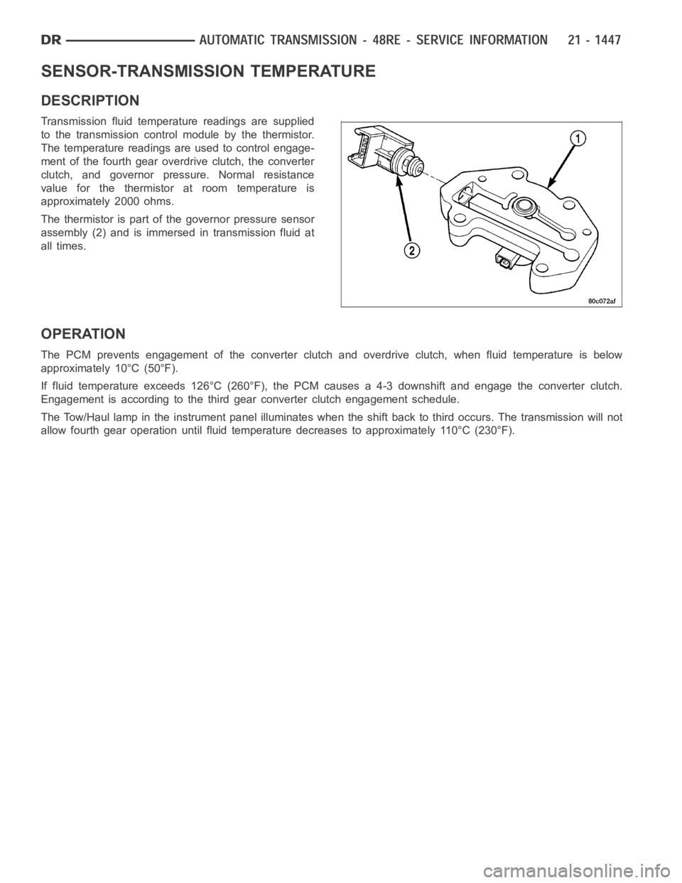
Transmission fluid temperature readings are supplied
to the transmission control module by the thermistor.
The temperature readings are used to control engage-
ment of the fourth gear overdrive clutch, the converter
clutch, and governor pressure. Normal resistance
value for the thermistor at room temperature is
approximately 2000 ohms.
The thermistor is part of the governor pressure sensor
assembly (2) and is immersed in transmission fluid at
all times.
OPERATION
The PCM prevents engagement of the converter clutch and overdrive clutch,when fluid temperature is below
approximately 10°C (50°F).
If fluid temperature exceeds 126°C (260°F), the PCM causes a 4-3 downshiftand engage the converter clutch.
Engagement is according to the third gear converter clutch engagement schedule.
The Tow/Haul lamp in the instrument panel illuminates when the shift back to third occurs. The transmission will not
allow fourth gear operation until fluid temperature decreases to approximately 110°C (230°F).
Page 3993 of 5267

Manual lever detent ball.
Throttle lever.
Fluid filter.
Pressure adjusting screw bracket.
Governor pressure solenoid.
Governor pressure sensor (includes transmission temperature thermistor).
Converter clutch/overdrive solenoid assembly and harness.
Governor housing gasket.
Solenoid case connector O-rings.
1. Shift transmission into NEUTRAL.
2. Raise vehicle.
3. Remove gearshift and throttle levers from shaft of
valve body manual lever.
4. Disconnect wires at solenoid case connector (1).
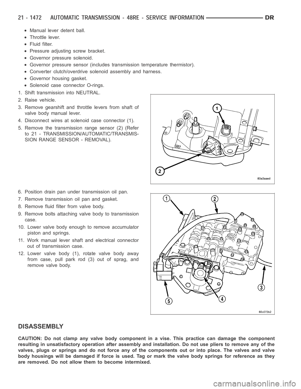
5. Remove the transmission range sensor (2) (Refer
to 21 - TRANSMISSION/AUTOMATIC/TRANSMIS-
SION RANGE SENSOR - REMOVAL).
6. Position drain pan under transmission oil pan.
7. Remove transmission oil pan and gasket.
8. Remove fluid filter from valve body.
9. Remove bolts attaching valve body to transmission
case.
10. Lower valve body enough to remove accumulator
piston and springs.
11. Work manual lever shaft and electrical connector
out of transmission case.
12. Lower valve body (1), rotate valve body away
from case, pull park rod (3) out of sprag, and
remove valve body.
DISASSEMBLY
CAUTION: Do not clamp any valve body component in a vise. This practice can damage the component
resulting in unsatisfactory operation after assembly and installation.Do not use pliers to remove any of the
valves, plugs or springs and do not force any of the components out or into place. The valves and valve
body housings will be damaged if force is used. Tag or mark the valve body springs for reference as they
are removed. Do not allow them to become intermixed.
Page 3994 of 5267
1. Disconnect wires from governor pressure sensor
and solenoid.
2. Remove screws attaching governor body and
retainer plate to transfer plate.
3. Remove retainer plate, governor body and gasket
from transfer plate.
4. Remove governor pressure sensor from governor
body.
5. Remove governor pressure solenoid by pulling it
straight out of bore in governor body. Remove and
discard solenoid O-rings if worn, cut, or torn.
6. Remove small shoulder bolt that secures solenoid
harness case connector (1) to 3-4 accumulator
housing (2). Retain shoulder bolt. Either tape it to
harness or thread it back into accumulator housing
after connector removal.
7. Unhook overdrive/converter solenoid harness (1)
from 3-4 accumulator cover plate (2)
.
8. Turn valve body over and remove screws that
attach overdrive/converter solenoid assembly (1) to
valve body.