2006 DODGE RAM SRT-10 sensor
[x] Cancel search: sensorPage 3836 of 5267
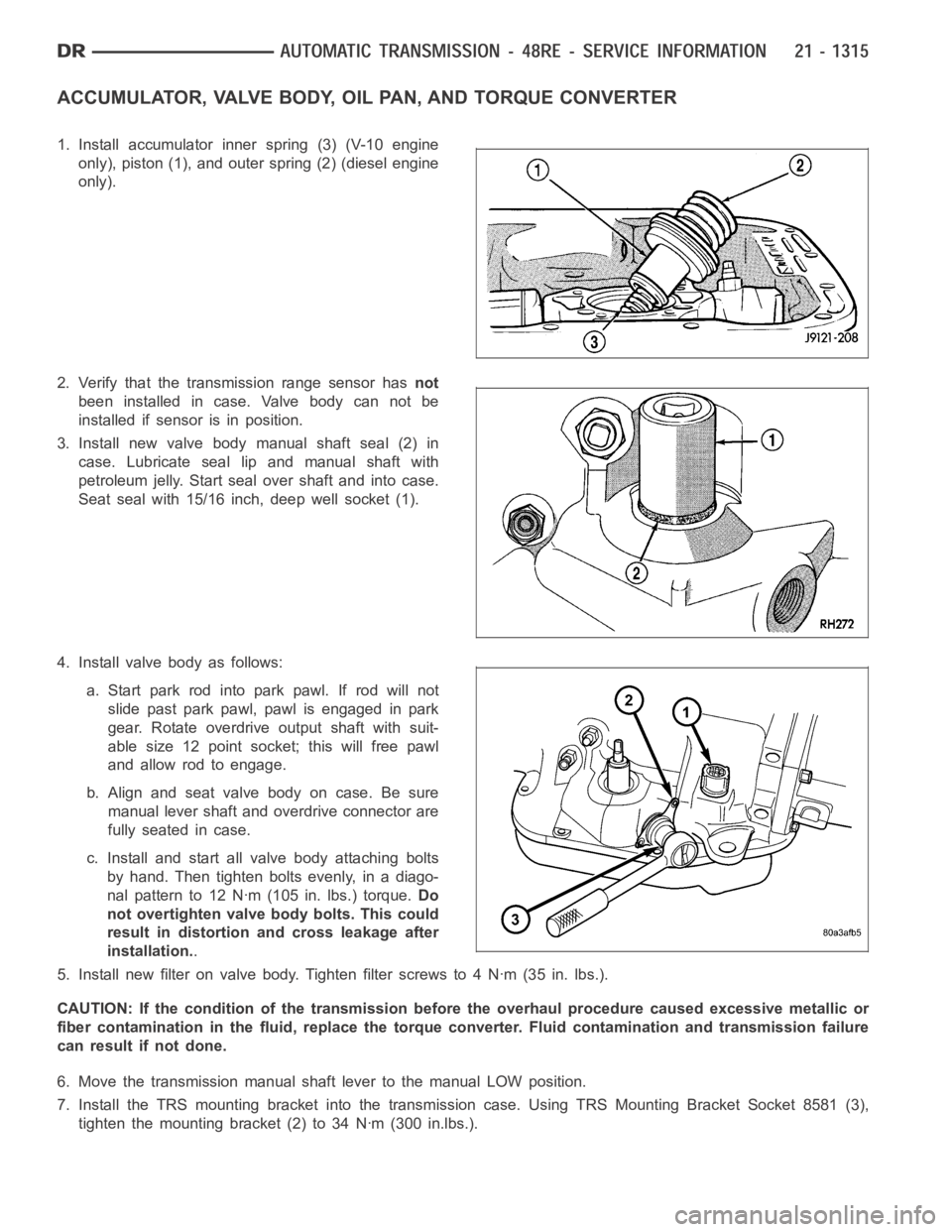
ACCUMULATOR, VALVE BODY, OIL PAN, AND TORQUE CONVERTER
1. Install accumulator inner spring (3) (V-10 engine
only), piston (1), and outer spring (2) (diesel engine
only).
2. Verify that the transmission range sensor hasnot
been installed in case. Valve body can not be
installed if sensor is in position.
3. Install new valve body manual shaft seal (2) in
case. Lubricate seal lip and manual shaft with
petroleum jelly. Start seal over shaft and into case.
Seat seal with 15/16 inch, deep well socket (1).
4. Install valve body as follows:
a. Start park rod into park pawl. If rod will not
slide past park pawl, pawl is engaged in park
gear. Rotate overdrive output shaft with suit-
able size 12 point socket; this will free pawl
and allow rod to engage.
b.Alignandseatvalvebodyoncase.Besure
manual lever shaft and overdrive connector are
fully seated in case.
c. Install and start all valve body attaching bolts
by hand. Then tighten bolts evenly, in a diago-
nal pattern to 12 Nꞏm (105 in. lbs.) torque.Do
not overtighten valve body bolts. This could
result in distortion and cross leakage after
installation..
5. Install new filter on valve body. Tighten filter screws to 4 Nꞏm (35 in. lbs.).
CAUTION: If the condition of the transmission before the overhaul procedure caused excessive metallic or
fiber contamination in the fluid, replace the torque converter. Fluid contamination and transmission failure
can result if not done.
6. Move the transmission manual shaft lever to the manual LOW position.
7. Install the TRS mounting bracket into the transmission case. Using TRS Mounting Bracket Socket 8581 (3),
tighten the mounting bracket (2) to 34 Nꞏm (300 in.lbs.).
Page 3837 of 5267
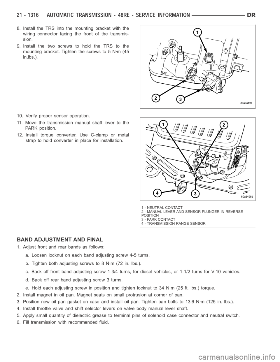
8. Install the TRS into the mounting bracket with the
wiring connector facing the front of the transmis-
sion.
9. Install the two screws to hold the TRS to the
mounting bracket. Tighten the screws to 5 Nꞏm (45
in.lbs.).
10. Verify proper sensor operation.
11. Move the transmission manual shaft lever to the
PARK position.
12. Install torque converter. Use C-clamp or metal
strap to hold converter in place for installation.
BAND ADJUSTMENT AND FINAL
1. Adjust front and rear bands as follows:
a. Loosen locknut on each band adjusting screw 4-5 turns.
b. Tighten both adjusting screws to 8 Nꞏm (72 in. lbs.).
c. Back off front band adjusting screw 1-3/4 turns, for diesel vehicles, or1-1/2 turns for V-10 vehicles.
d. Back off rear band adjusting screw 3 turns.
e. Hold each adjusting screw in position and tighten locknut to 34 Nꞏm (25 ft. lbs.) torque.
2. Install magnet in oil pan. Magnet seats on small protrusion at corner of pan.
3. Position new oil pan gasket on case and install oil pan. Tighten pan boltsto 13.6 Nꞏm (125 in. lbs.).
4. Install throttle valve and shift selector levers on valve body manual lever shaft.
5. Apply small quantity of dielectric grease to terminal pins of solenoid case connector and neutral switch.
6. Fill transmission with recommended fluid.
1 - NEUTRAL CONTACT
2 - MANUAL LEVER AND SENSOR PLUNGER IN REVERSE
POSITION
3 - PARK CONTACT
4 - TRANSMISSION RANGE SENSOR
Page 3839 of 5267

9. For vehicles equipped with a gas engine;
a. Position transmission on jack and secure it
with chains.
b. Check condition of converter driveplate.
Replace the plate if cracked, distorted or dam-
aged.Also be sure transmission dowel pins
are seated in engine block and protrude far
enough to hold transmission in alignment.
c. Raise transmission and align converter with
drive plate and converter housing with engine
block.
d. Move transmission forward. Then raise, lower
or tilt transmission to align converter housing
with engine block dowels.
e. Carefully work transmission forward and over
engine block dowels until converter hub is
seated in crankshaft.
f. Install bolts (1) attaching transmission (3) to
engine (2).
10. Install rear support.
11. Install the rear transmission crossmember.
12. Lower transmission onto crossmember and install
bolts attaching transmission mount to crossmem-
ber.
13. Remove engine support fixture.
14. Install the transfer case, if equipped. (Refer to 21
- TRANSMISSION AND TRANSFER CASE/
TRANSFER CASE - INSTALLATION)
15. Install crankshaft position sensor. (Refer to 14 -
FUEL SYSTEM/FUEL INJECTION/CRANKSHAFT
POSITION SENSOR - INSTALLATION)
16. Connect gearshift cable (1) and throttle cable (gas
engines only) to transmission.
Page 3842 of 5267
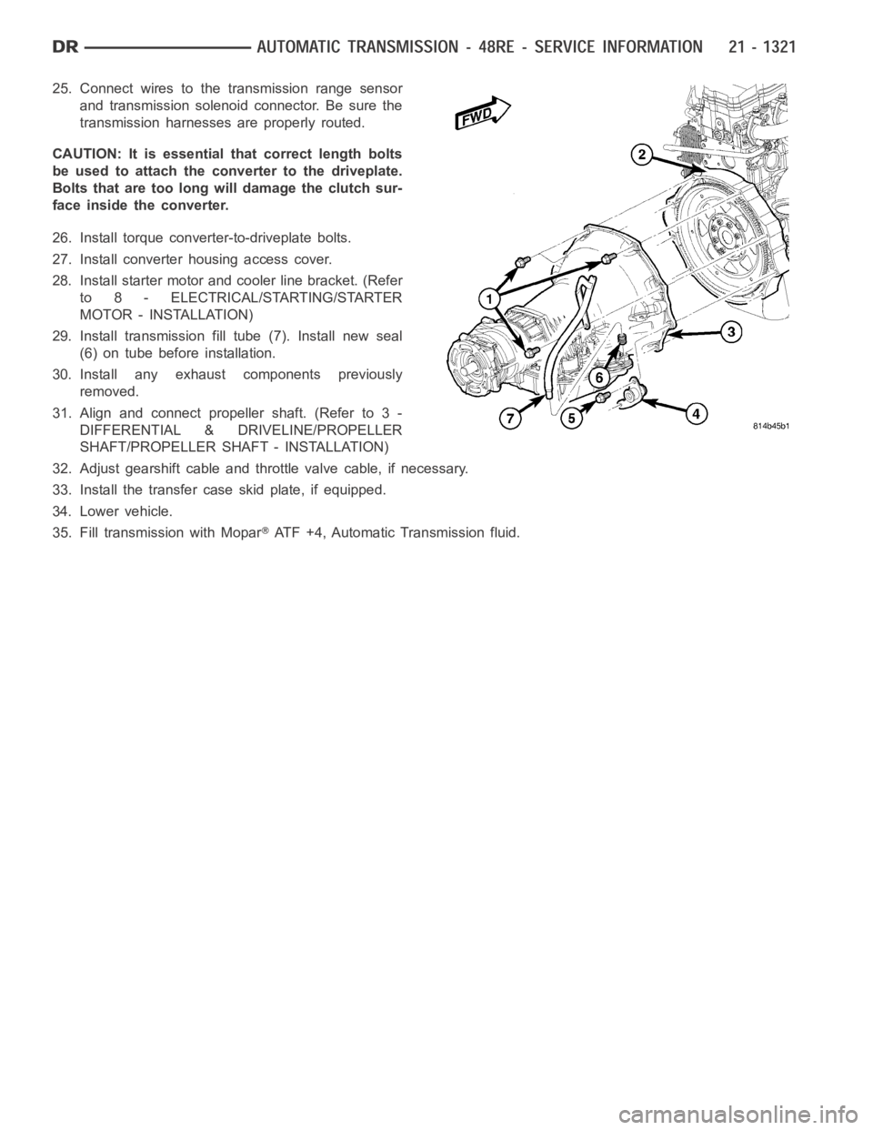
25. Connect wires to the transmission range sensor
and transmission solenoid connector. Be sure the
transmission harnesses are properly routed.
CAUTION: It is essential that correct length bolts
be used to attach the converter to the driveplate.
Bolts that are too long will damage the clutch sur-
face inside the converter.
26. Install torque converter-to-driveplate bolts.
27. Install converter housing access cover.
28. Install starter motor and cooler line bracket. (Refer
to 8 - ELECTRICAL/STARTING/STARTER
MOTOR - INSTALLATION)
29. Install transmission fill tube (7). Install new seal
(6) on tube before installation.
30. Install any exhaust components previously
removed.
31. Align and connect propeller shaft. (Refer to 3 -
DIFFERENTIAL & DRIVELINE/PROPELLER
SHAFT/PROPELLER SHAFT - INSTALLATION)
32. Adjust gearshift cable and throttle valve cable, if necessary.
33. Install the transfer case skid plate, if equipped.
34. Lower vehicle.
35. Fill transmission with Mopar
ATF +4, Automatic Transmission fluid.
Page 3859 of 5267
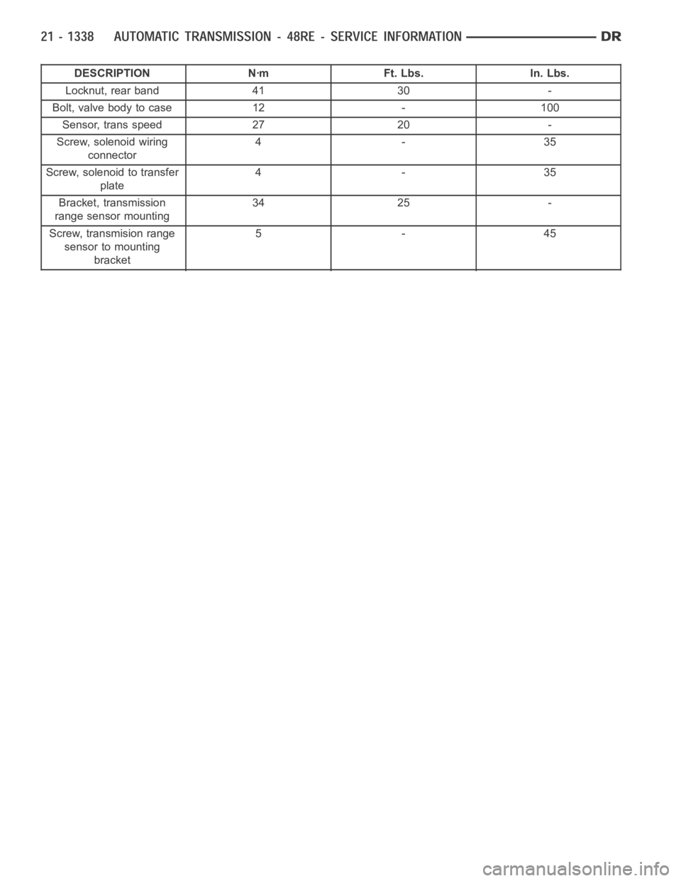
DESCRIPTION Nꞏm Ft. Lbs. In. Lbs.
Locknut, rear band 41 30 -
Bolt, valve body to case 12 - 100
Sensor, trans speed 27 20 -
Screw, solenoid wiring
connector4-35
Screw, solenoid to transfer
plate4-35
Bracket, transmission
range sensor mounting34 25 -
Screw, transmision range
sensor to mounting
bracket5-45
Page 3868 of 5267
GOVERNOR-ELECTRONIC
DESCRIPTION
Governor pressure is controlled electronically. Components used for governor pressure control include:
Governor body
Valve body transfer plate
Governor pressuresolenoid valve
Governor pressure sensor
Fluid temperature thermistor
Throttle position sensor (TPS)
Transmission speed sensor
Powertrain control module (PCM)
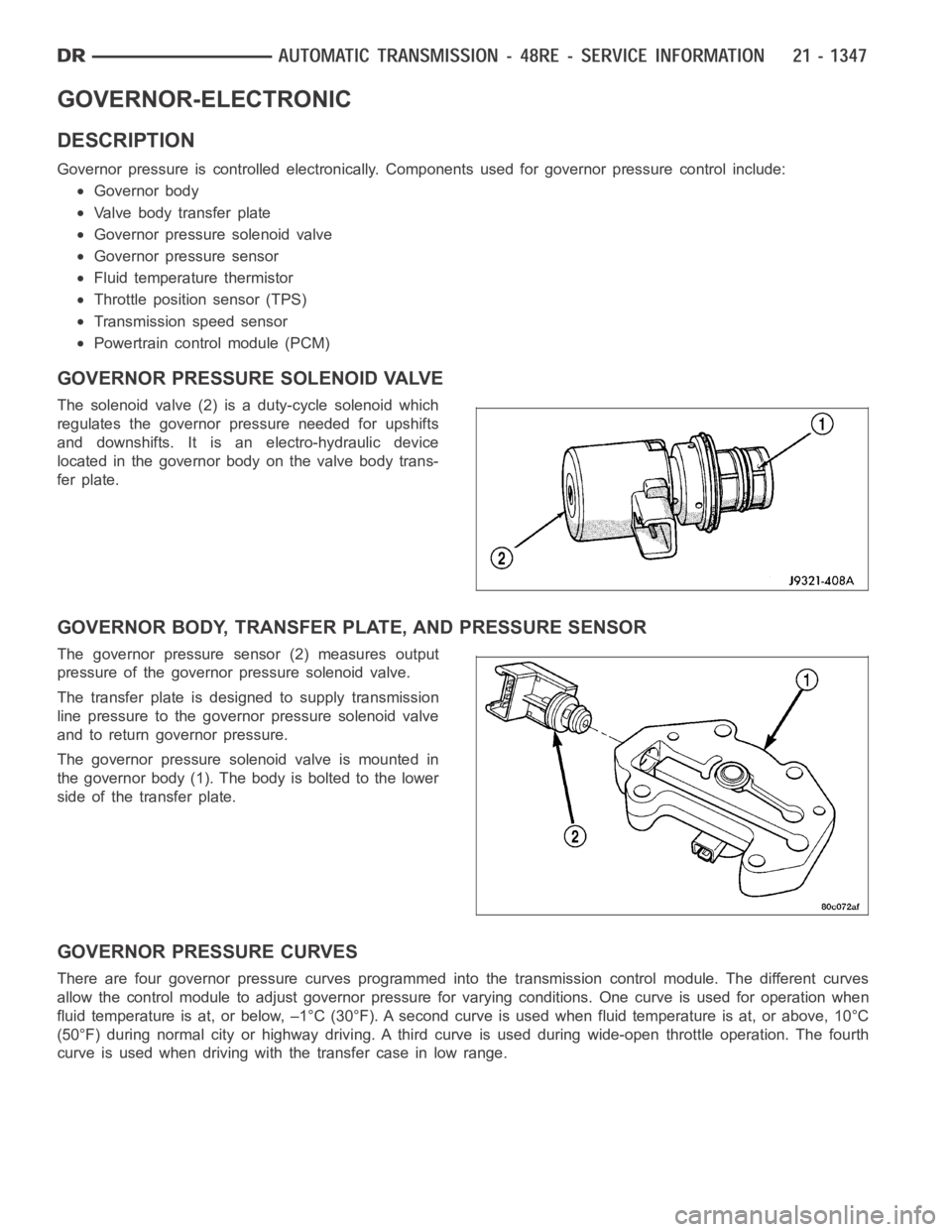
GOVERNOR PRESSURE SOLENOID VALVE
The solenoid valve (2) is a duty-cycle solenoid which
regulates the governor pressure needed for upshifts
and downshifts. It is an electro-hydraulic device
located in the governor body on the valve body trans-
fer plate.
GOVERNOR BODY, TRANSFER PLATE, AND PRESSURE SENSOR
The governor pressure sensor (2) measures output
pressure of the governor pressure solenoid valve.
The transfer plate is designed to supply transmission
line pressure to the governor pressure solenoid valve
and to return governor pressure.
The governor pressure solenoid valve is mounted in
the governor body (1). The body is bolted to the lower
side of the transfer plate.
GOVERNOR PRESSURE CURVES
There are four governor pressure curves programmed into the transmissioncontrol module. The different curves
allow the control module to adjust governor pressure for varying conditions. One curve is used for operation when
fluid temperature is at, or below, –1°C (30°F). A second curve is used when fluid temperature is at, or above, 10°C
(50°F) during normal city or highway driving. A third curve is used during wide-open throttle operation. The fourth
curve is used when driving with the transfer case in low range.
Page 3869 of 5267
OPERATION
Compensation is required for performance variations of two of the input devices. Though the slope of the transfer
functions is tightly controlled, offset may vary due to various environmental factors or manufacturing tolerances.
The pressure transducer is affected by barometric pressure as well as temperature. Calibration of the zero pressure
offset is required to compensate for shifting output due to these factors.
Normal calibration will be performed when sump temperature is above 50 degrees F, or in the absence of sump
temperature data, after the first 10 minutes of vehicle operation. Calibration of the pressure transducer offset occurs
each time the output shaft speed falls below 200 RPM. Calibration shall be repeated each 3 seconds the output
shaft speed is below 200 RPM. A 0.5 second pulse of 95% duty cycle is applied to the governor pressure solenoid
valve and the transducer output is read during this pulse. Averaging of thetransducer signal isnecessary to reject
electrical noise.
Under cold conditions (below 50 degrees F sump), the governor pressure solenoid valve response may be too slow
to guarantee 0 psi during the 0.5 second calibration pulse. Calibration pulses are continued during this period, how-
ever the transducer output valves are discarded. Transducer offset must be read at key-on, under conditions which
promote a stable reading. This value is retained and becomes the offset during the
coldperiod of operation.
GOVERNOR PRESSURE SOLENOID VALVE
The inlet side of the solenoid valve is exposed to normal transmission linepressure. The outlet side of the valve
leads to the valve body governor circuit.
The solenoid valve regulates line pressure to produce governor pressure.Theaveragecurrentsuppliedtothesole-
noid controls governor pressure. One amp current produces zero kPa/psi governor pressure. Zero amps sets the
maximum governor pressure.
The powertrain control module (PCM) turns on the trans control relay whichsupplies electrical power to the solenoid
valve. Operating voltage is 12 volts (DC). The PCM controls the ground sideof the solenoid using the governor
pressure solenoidcontrol circuit.
GOVERNOR PRESSURE SENSOR
The sensor output signal provides the necessary feedback to the PCM. This feedback is needed to adequately
control governor pressure.
GOVERNOR BODY AND TRANSFER PLATE
The transfer plate channels line pressure to the solenoid valve through the governor body. It also channels governor
pressure from the solenoid valve to the governor circuit. It is the solenoid valve that develops the necessary gov-
ernor pressure.
GOVERNOR PRESSURE CURVES
LOW TRANSMISSION FLUID TEMPERATURE
When the transmission fluid is cold the conventional governor can delay shifts, resulting in higher than normal shift
speeds and harsh shifts. The electronically controlled low temperature governor pressure curve is higher than nor-
mal to make the transmission shift at normal speeds and sooner. The PCM usesa temperature sensor in the trans-
mission oil sump to determine when low temperature governor pressure is needed.
NORMAL OPERATION
Normal operation is refined through the increased computing power of the PCM and through access to data on
engine operating conditions provided by the PCM that were not available with the previous stand-alone electronic
module. This facilitated the development of a load adaptive shift strategy - the ability to alter the shift schedule in
response to vehicle load condition. One manifestation of this capabilityis grade
huntingprevention - the ability of
the transmission logic to delay an upshift on a grade if the engine does not have sufficient power to maintain speed
in the higher gear. The 3-2 downshift and the potential for hunting betweengears occurs with a heavily loaded
vehicle or on steep grades. When hunting occurs, it is very objectionable because shifts are frequent and accom-
panied by large changes in noise and acceleration.
Page 3870 of 5267
WIDE OPEN THROTTLE OPERATION
In wide-open throttle (WOT) mode, adaptive memory in the PCM assures that up-shifts occur at the preprogrammed
optimum speed. WOT operation is determined from the throttle position sensor, which is also a part of the emission
control system. The initial setting for the WOT upshift is below the optimum engine speed. As WOT shifts are
repeated, the PCM learns the time required to complete the shifts by comparing the engine speed when the shifts
occur to the optimum speed. After each shift, the PCM adjusts the shift point until the optimum speed is reached.
The PCM also considers vehicle loading, grade and engine performance changes due to high altitude in determining
when to make WOT shifts. It does this by measuring vehicle and engine acceleration and then factoring in the shift
time.
TRANSFER CASE LOW RANGE OPERATION
On four-wheel drive vehicles operating in low range, the engine can accelerate to its peak more rapidly than in
Normal range, resulting in delayed shifts and undesirable engine
flare.The low range governor pressure curve is
also higher than normal to initiate upshifts sooner. The PCM compares electronic vehicle speed signal used by the
speedometer to the transmission output shaft speed signal to determine when the transfer case is in low range.
REMOVAL
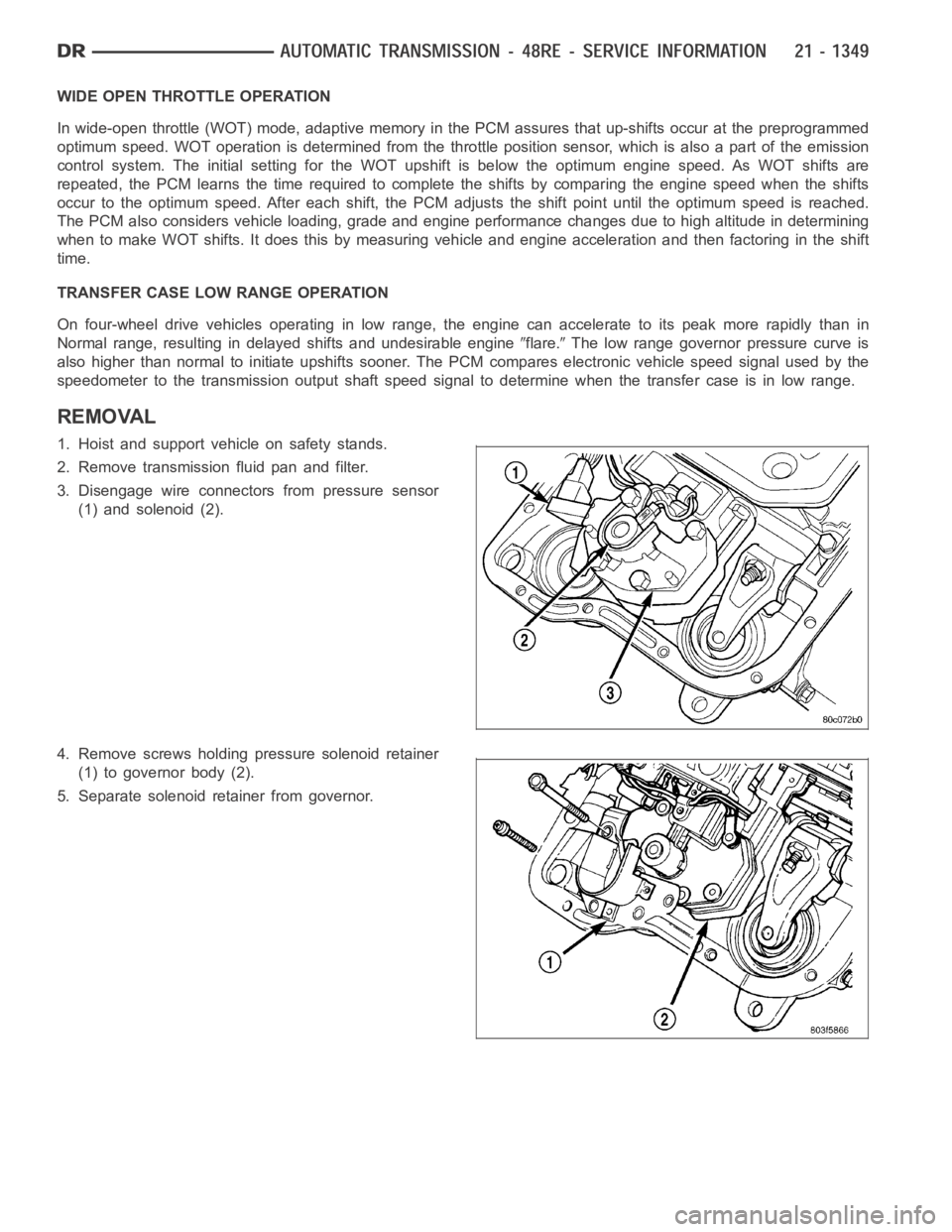
1. Hoist and support vehicle on safety stands.
2. Remove transmission fluid pan and filter.
3. Disengage wire connectors from pressure sensor
(1) and solenoid (2).
4. Remove screws holding pressure solenoid retainer
(1) to governor body (2).
5. Separate solenoid retainer from governor.