Page 4265 of 5267
TRANSFER CASE - NV273 - SERVICE INFORMATION
DESCRIPTION
The NV273 is an electronically controlled part-time transfer case with a low range gear reduction system. The
NV273 has three operating ranges plus a NEUTRAL position. The low range system provides a gear reduction ratio
for increased low speed torque capability.
The geartrain is mounted in two aluminum case halves attached with bolts. The mainshaft front and rear bearings
are mounted in aluminum case halves.
OPERATING RANGES
Transfer case operating ranges are:
2WD (2-wheel drive).
4HI (4-wheel drive).
4LO (4-wheel drive low range).
NEUTRAL.
The 2WD range is for use on any road surface at any time.
The 4HI and 4LO ranges are for off road use only. They are not for use on hard surface roads. The only exception
being when the road surface is wet or slippery or covered by ice and snow.
The low range reduction gear system is operative in 4LO range only. This range is for extra pulling power in off road
situations. Low range reduction ratio is 2.72:1.
SHIFT MECHANISM
Operating ranges are selected with a dash mounted shift selector switch. The shift selector switch provides a input
to the Transfer Case Control Module (TCCM) to indicate the driver’s desireto change operating ranges. The TCCM
uses this input, along with input from the transfer case mounted mode sensor and information from the vehicle’s
bus, to determine if a shift is permitted. If the TCCM decides the shift is permitted, the TCCM controls the shift
motor, mounted to the exterior of the transfer case, to perform the shift.
IDENTIFICATION
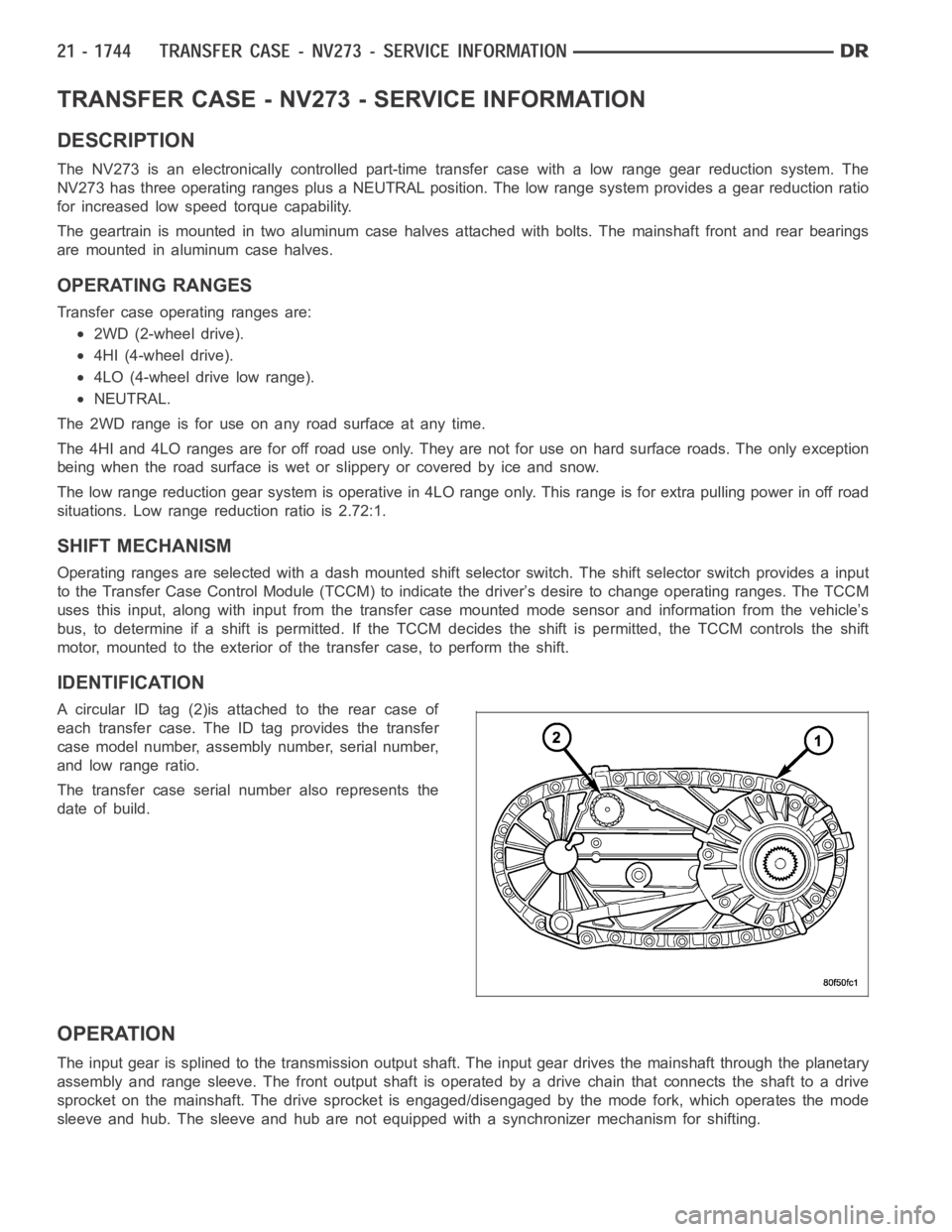
A circular ID tag (2)is attached to the rear case of
each transfer case. The ID tag provides the transfer
case model number, assembly number, serial number,
and low range ratio.
The transfer case serial number also represents the
date of build.
OPERATION
The input gear is splined to the transmission output shaft. The input gear drives the mainshaft through the planetary
assembly and range sleeve. The front output shaft is operated by a drive chain that connects the shaft to a drive
sprocket on the mainshaft. The drive sprocket is engaged/disengaged by themodefork,whichoperatesthemode
sleeve and hub. The sleeve and hub are not equipped with a synchronizer mechanism for shifting.
Page 4267 of 5267
REMOVAL
1. Shift transfer case into 2WD.
2. Raise vehicle.
3. Drain transfer case lubricant.
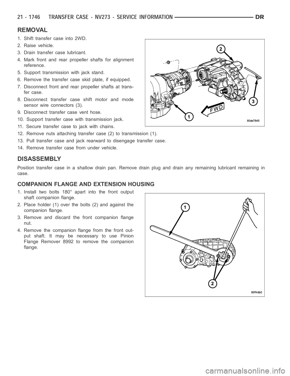
4. Mark front and rear propeller shafts for alignment
reference.
5. Support transmission with jack stand.
6. Remove the transfer case skid plate, if equipped.
7. Disconnect front and rear propeller shafts at trans-
fer case.
8. Disconnect transfer case shift motor and mode
sensor wire connectors (3).
9. Disconnect transfer case vent hose.
10. Support transfer case with transmission jack.
11. Secure transfer case to jack with chains.
12. Remove nuts attaching transfer case (2) to transmission (1).
13. Pull transfer case and jack rearward to disengage transfer case.
14. Remove transfer case from under vehicle.
DISASSEMBLY
Position transfer case in a shallow drain pan. Remove drain plug and drain any remaining lubricant remaining in
case.
COMPANION FLANGE AND EXTENSION HOUSING
1. Install two bolts 180° apart into the front output
shaft companion flange.
2. Place holder (1) over the bolts (2) and against the
companion flange.
3. Remove and discard the front companion flange
nut.
4. Remove the companion flange from the front out-
put shaft. It may be necessary to use Pinion
Flange Remover 8992 to remove the companion
flange.
Page 4295 of 5267
13. Install detent plunger (4), spring (3), and plug (2).
Tighten the plug to 16-25 Nꞏm (12-18 ft. lbs.).
14. Position the shift motor and mode sensor assem-
bly (2) onto the transfer case (1).
15. Install the bolts (3) to hold the shift motor and
mode sensor assembly (2) to the transfer case
(1). Tighten the bolts to 16-25 Nꞏm (12-18 ft. lbs.).
Page 4301 of 5267
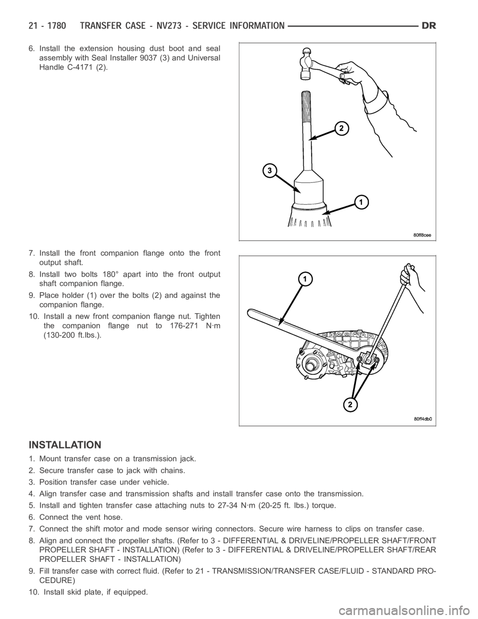
6. Install the extension housing dust boot and seal
assembly with Seal Installer 9037 (3) and Universal
Handle C-4171 (2).
7. Install the front companion flange onto the front
output shaft.
8. Install two bolts 180° apart into the front output
shaft companion flange.
9. Place holder (1) over the bolts (2) and against the
companion flange.
10. Install a new front companion flange nut. Tighten
the companion flange nut to 176-271 Nꞏm
(130-200 ft.lbs.).
INSTALLATION
1. Mount transfer case on a transmission jack.
2. Secure transfer case to jack with chains.
3. Position transfer case under vehicle.
4. Align transfer case and transmission shafts and install transfer case onto the transmission.
5. Install and tighten transfer case attaching nuts to 27-34 Nꞏm (20-25 ft.lbs.) torque.
6. Connect the vent hose.
7. Connect the shift motor and mode sensor wiring connectors. Secure wire harness to clips on transfer case.
8. Align and connect the propeller shafts. (Refer to 3 - DIFFERENTIAL & DRIVELINE/PROPELLER SHAFT/FRONT
PROPELLER SHAFT - INSTALLATION) (Refer to 3 - DIFFERENTIAL & DRIVELINE/PROPELLER SHAFT/REAR
PROPELLER SHAFT - INSTALLATION)
9. Fill transfer case with correct fluid. (Refer to 21 - TRANSMISSION/TRANSFER CASE/FLUID - STANDARD PRO-
CEDURE)
10. Install skid plate, if equipped.
Page 4302 of 5267
11. Remove transmission jack and support stand.
12. Lower vehicle and verify transfer case shift operation.
SPECIFICATIONS
TRANSFER CASE - NV273
TORQUE SPECIFICATIONS
DESCRIPTION N-m Ft. Lbs. In. Lbs.
Plug, Detent 16-24 12-18 -
Plug, Drain/Fill 20-34 15-25 -
Bolt, Extension Housing 27-34 20-25 -
Bolt, Case Half 27-34 20-25 -
Support, Sector 27-34 20-25 -
Nuts, Mounting 30-41 20-30 -
Bolts, Shift Motor and
Mode Sensor Assembly16-25 12-18 -
Nut, Companion Flange 176-271 130-200 -
Page 4308 of 5267
SENSOR-MODE
DESCRIPTION
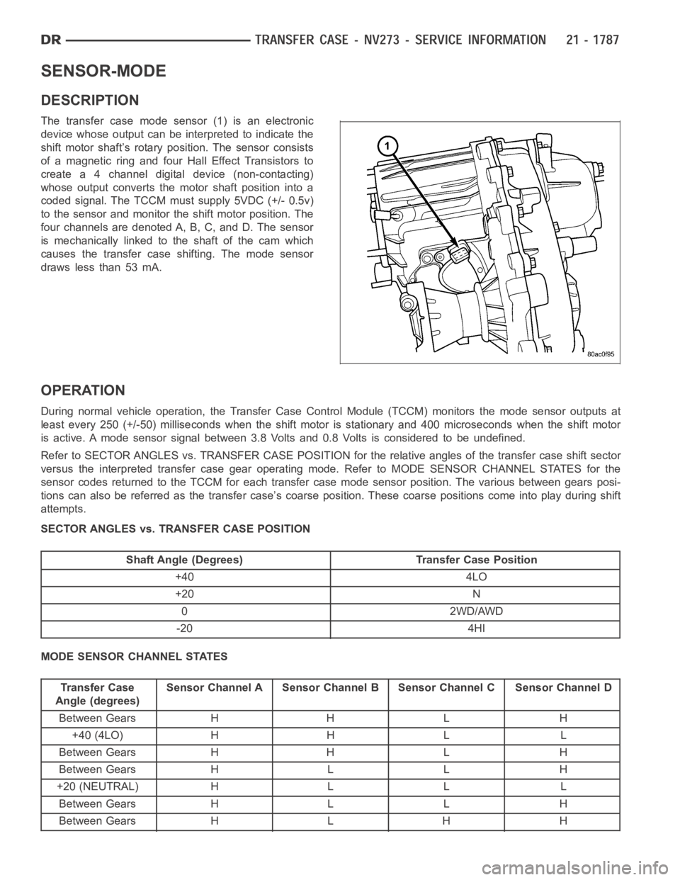
The transfer case mode sensor (1) is an electronic
device whose output can be interpreted to indicate the
shift motor shaft’s rotary position. The sensor consists
of a magnetic ring and four Hall Effect Transistors to
create a 4 channel digital device (non-contacting)
whose output converts the motor shaft position into a
coded signal. The TCCM must supply 5VDC (+/- 0.5v)
to the sensor and monitor the shift motor position. The
four channels are denoted A, B, C, and D. The sensor
is mechanically linked to the shaft of the cam which
causes the transfer case shifting. The mode sensor
draws less than 53 mA.
OPERATION
During normal vehicle operation, the Transfer Case Control Module (TCCM)monitors the mode sensor outputs at
least every 250 (+/-50) milliseconds when the shift motor is stationary and 400 microseconds when the shift motor
is active. A mode sensor signal between 3.8 Volts and 0.8 Volts is considered to be undefined.
Refer to SECTOR ANGLES vs. TRANSFER CASE POSITION for the relative angles of the transfer case shift sector
versus the interpreted transfer case gear operating mode. Refer to MODE SENSOR CHANNEL STATES for the
sensor codes returned to the TCCM for each transfer case mode sensor position. The various between gears posi-
tions can also be referred as the transfer case’s coarse position. These coarse positions come into play during shift
attempts.
SECTOR ANGLES vs. TRANSFER CASE POSITION
Shaft Angle (Degrees) Transfer Case Position
+40 4LO
+20 N
0 2WD/AWD
-20 4HI
MODE SENSOR CHANNEL STATES
Transfer Case
Angle (degrees)Sensor Channel A Sensor Channel B Sensor Channel C Sensor Channel D
Between Gears H H L H
+40 (4LO) H H L L
Between Gears H H L H
Between Gears H L L H
+20 (NEUTRAL) H L L L
Between Gears H L L H
Between Gears H L H H
Page 4309 of 5267
Transfer Case
Angle (degrees)Sensor Channel A Sensor Channel B Sensor Channel C Sensor Channel D
0 (2WD/AWD) H L H L
Between Gears H L H H
Between Gears L L H H
-20 (4HI) L L H L
Between Gears L L H H
Between Gears L H H H
Page 4310 of 5267
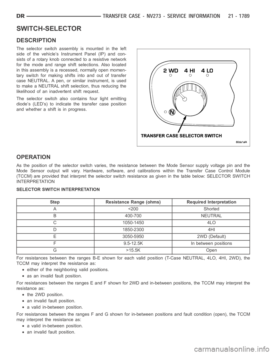
SWITCH-SELECTOR
DESCRIPTION
The selector switch assembly is mounted in the left
side of the vehicle’s Instrument Panel (IP) and con-
sists of a rotary knob connected to a resistive network
for the mode and range shift selections. Also located
in this assembly is a recessed, normally open momen-
tary switch for making shifts into and out of transfer
case NEUTRAL. A pen, or similar instrument, is used
to make a NEUTRAL shift selection, thus reducing the
likelihood of an inadvertent shift request.
The selector switch also contains four light emitting
diode’s (LED’s) to indicate the transfer case position
and whether a shift is in progress.
OPERATION
As the position of the selector switchvaries, the resistance between the Mode Sensor supply voltage pin and the
Mode Sensor output will vary. Hardware, software, and calibrations within the Transfer Case Control Module
(TCCM) are provided that interpret the selector switch resistance as giveninthetablebelow:SELECTORSWITCH
INTERPRETATION
SELECTOR SWITCH INTERPRETATION
Step Resistance Range (ohms) Required Interpretation
A <200 Shorted
B 400-700 NEUTRAL
C 1050-1450 4LO
D 1850-2300 4HI
E 3050-5950 2WD (Default)
F 9.5-12.5K In between positions
G>15.5KOpen
For resistances between the ranges B-E shown for each valid position (T-Case NEUTRAL, 4LO, 4HI, 2WD), the
TCCM may interpret the resistance as:
either of the neighboring valid positions.
as an invalid fault position.
For resistances between the ranges E and F shown for 2WD and in-between positions, the TCCM may interpret the
resistance as:
the 2WD position.
an invalid fault position.
a valid in-between position.
For resistances between the ranges F and G shown for in-between positions and fault condition (open), the TCCM
may interpret the resistance as:
a valid in-between position.
an invalid fault position.