2006 DODGE RAM SRT-10 key
[x] Cancel search: keyPage 2444 of 5267
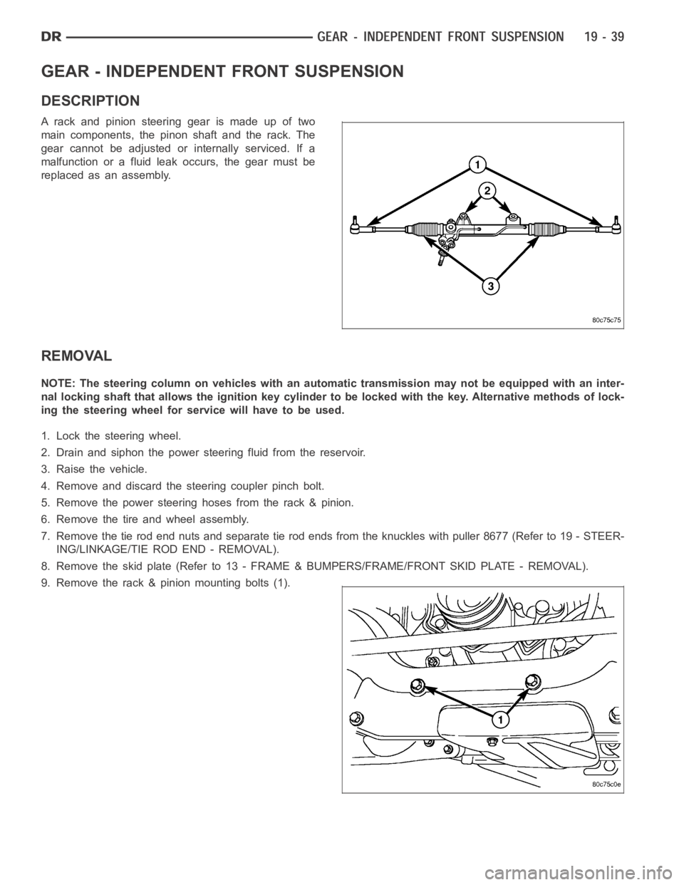
GEAR - INDEPENDENT FRONT SUSPENSION
DESCRIPTION
A rack and pinion steering gear is made up of two
main components, the pinon shaft and the rack. The
gear cannot be adjusted or internally serviced. If a
malfunction or a fluid leak occurs, the gear must be
replaced as an assembly.
REMOVAL
NOTE: The steering column on vehicles with an automatic transmission may not be equipped with an inter-
nal locking shaft that allows the ignition key cylinder to be locked with the key. Alternative methods of lock-
ing the steering wheel for service will have to be used.
1. Lock the steering wheel.
2. Drain and siphon the power steering fluid from the reservoir.
3. Raise the vehicle.
4. Remove and discard the steering coupler pinch bolt.
5. Remove the power steering hoses from the rack & pinion.
6. Remove the tire and wheel assembly.
7. Remove the tie rod end nuts and separate tie rod ends from the knuckles withpuller8677(Referto19-STEER-
ING/LINKAGE/TIE ROD END - REMOVAL).
8. Remove the skid plate (Refer to 13 - FRAME & BUMPERS/FRAME/FRONT SKID PLATE - REMOVAL).
9. Remove the rack & pinion mounting bolts (1).
Page 2449 of 5267
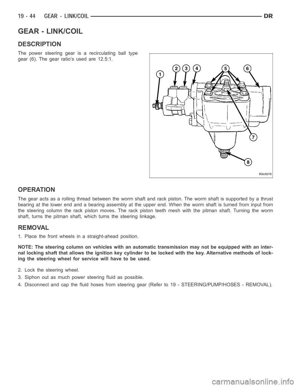
GEAR - LINK/COIL
DESCRIPTION
The power steering gear is a recirculating ball type
gear (6). The gear ratio’s used are 12.5:1.
OPERATION
The gear acts as a rolling thread between the worm shaft and rack piston. Theworm shaft is supported by a thrust
bearing at the lower end and a bearing assembly at the upper end. When the worm shaft is turned from input from
the steering column the rack piston moves. The rack piston teeth mesh with the pitman shaft. Turning the worm
shaft, turns the pitman shaft, which turns the steering linkage.
REMOVAL
1. Place the front wheels in a straight-ahead position.
NOTE: The steering column on vehicles with an automatic transmission may not be equipped with an inter-
nal locking shaft that allows the ignition key cylinder to be locked with the key. Alternative methods of lock-
ing the steering wheel for service will have to be used.
2. Lock the steering wheel.
3. Siphon out as much power steering fluid as possible.
4. Disconnect and cap the fluid hoses from steering gear (Refer to 19 - STEERING/PUMP/HOSES - REMOVAL).
Page 2739 of 5267
P0604-INTERNAL CONTROL MODULE RAM
For a complete wiring diagramRefer to Section 8W.
When Monitored:
One time after the ignition key is turned to the run position.
Set Condition:
The read value does not match the written value in any RAM location.
Possible Causes
PCM - INTERNAL ERROR
Always perform the Pre-Diagnostic Troubleshooting procedure before proceeding. (Refer to 21 - TRANSMIS-
SION/TRANSAXLE/AUTOMATIC - 42RLE - STANDARD PROCEDURE)
Theory of Operation
After the controller is reset, the microprocessor checks the integrity ofeach RAM location by writing to it and read-
ing back from it. The read value should be the same as the written value. MIL on after 10 seconds of vehicle oper-
ation and transmission will be placed in limp-in.
Diagnostic Test
1.PCM - INTERNAL ERROR
If there are no possible causes remaining, view repair.
Repair
Using the schematics as a guide, check the Powertrain Control Module (PCM)terminals for corrosion,
damage, or terminal push out. Pay particular attention to all power and ground circuits. Check for Ser-
vice Information Tune-ups or Service Bulletins for any possible causes that may apply. If no problems
are found, replace the PCM per the Service Information. With the scan tool,perform QUICK LEARN.
Perform 42RLE TRANSMISSION VERIFICATION TEST - VER 1. (Refer to 21 - TRANSMISSION/
TRANSAXLE/AUTOMATIC - 42RLE - STANDARD PROCEDURE)
Page 2740 of 5267
P0605-INTERNAL CONTROL MODULE ROM
For a complete wiring diagramRefer to Section 8W.
When Monitored:
One time after the ignition key is turned to the run position.
Set Condition:
If the ROM checksum does not match a known constant.
Possible Causes
PCM - INTERNAL ERROR
Always perform the Pre-Diagnostic Troubleshooting procedure before proceeding. (Refer to 21 - TRANSMIS-
SION/TRANSAXLE/AUTOMATIC - 42RLE - STANDARD PROCEDURE)
Theory of Operation
After the controller is reset, the microprocessor checksthe integrity ofthe program memory (ROM). A checksum is
calculated by adding all used bytes in the program memory. The sum should bethesameasaknownconstant
stored in memory. MIL on after 10 seconds of vehicle operation and transmission will be placed in limp-in.
Diagnostic Test
1.PCM - INTERNAL ERROR
Using the schematics as a guide, inspect the wiring and connectors. Repairas necessary. Pay particular attention
to all power and ground circuits.
If there are no possible causes remaining, view repair.
Repair
Using the schematics as a guide, check the Powertrain Control Module (PCM)terminals for corrosion,
damage, or terminal push out. Pay particular attention to all power and ground circuits. Check for Ser-
vice Information Tune-ups or Service Bulletins for any possible causes that may apply. If no problems
are found, replace the PCM per the Service Information. With the scan tool,perform QUICK LEARN.
Perform 42RLE TRANSMISSION VERIFICATION TEST - VER 1. (Refer to 21 - TRANSMISSION/
TRANSAXLE/AUTOMATIC - 42RLE - STANDARD PROCEDURE)
Page 2741 of 5267
P0613-INTERNAL TRANSMISSION PROCESSOR
For a complete wiring diagramRefer to Section 8W.
When Monitored:
After the ignition key is turned to the run position and 60 seconds thereafter.
Set Condition:
Either of the following conditions occur 3 times in less than 590 milliseconds: The watchdog line remains high
after the watchdog test or the transmission relay coil is energized and remains on after the watchdog delay
expires.
Possible Causes
PCM - INTERNAL ERROR
Always perform the Pre-Diagnostic Troubleshooting procedure before proceeding. (Refer to 21 - TRANSMIS-
SION/TRANSAXLE/AUTOMATIC - 42RLE - STANDARD PROCEDURE)
Theory of Operation
The internal watchdog is a separate hardware circuit which continuously monitors the microprocessor. To make sure
the transmission is operating properly, the watchdog must receive a signal from the microprocessor within a specific
time window. MIL on after 10 seconds of vehicle operation and transmissionwill be placed in limp-in.
Diagnostic Test
1.PCM - INTERNAL ERROR
Using the schematics as a guide, inspect the wiring and connectors. Repairas necessary. Pay particular attention
to all power and ground circuits.
If there are no possible causes remaining, view repair.
Repair
Using the schematics as a guide, check the Powertrain Control Module (PCM)terminals for corrosion,
damage, or terminal push out. Pay particular attention to all power and ground circuits. Check for Ser-
vice Information Tune-ups or Service Bulletins for any possible causes that may apply. If no problems
are found, replace the PCM per the Service Information. With the scan tool,perform QUICK LEARN.
Perform 42RLE TRANSMISSION VERIFICATION TEST - VER 1. (Refer to 21 - TRANSMISSION/
TRANSAXLE/AUTOMATIC - 42RLE - STANDARD PROCEDURE)
Page 2801 of 5267
When Monitored:
Whenever the engine is running.
Set Condition:
The DTC is set if one of the pressure switches are open or closed at the wrong time in a given gear. If the
problem is identified for 3 successive key starts, the transmission will go into Limp-in mode and the MIL will
turn on after 10 seconds of vehicle operation.
Possible Causes
RELATED TIPM TCM POWER CONTROL CIRCUIT DTCS PRESENT
LOSS OF PRIME DTC PRESENT
(T50) L/R PRESSURE SWITCH SENSE CIRCUIT OPEN
(T50) L/R PRESSURE SWITCH SENSE CIRCUIT SHORT TO GROUND
(T50) L/R PRESSURE SWITCH SENSE CIRCUIT SHORT TO VOLTAGE
TRANSMISSION SOLENOID/PRESSURE SWITCH ASSEMBLY
POWERTRAIN CONTROL MODULE
Always perform the 42RLE Pre-Diagnostic Troubleshooting procedure before proceeding. (Refer to 21 -
TRANSMISSION/TRANSAXLE/AUTOMATIC - 42RLE - STANDARD PROCEDURE)
Theory of Operation
The Transmission system uses three pressure switches to monitor the fluidpressure in the LR, 2/4, and OD ele-
ments. The pressure switches are continuously monitored for the correct states in each gear. If a set condition is
identified, 1st gear and torque converter lock-up (EMCC) will be inhibited. The vehicle will launch in 2nd gear and
shift normally through the gears without allowing EMCC. If during the samekey start, the set condition is no longer
valid, the transmission will return to normal operation (1st and EMCC available). Limp-in will not occur unless DTC
P0841 is accompanied by a code P0706 and the MIL will illuminate after 5 minutes of substituted operation.
PRESSURE SWITCH STATES
GEAR L/R 2/4 OD
ROPOPOP
P/N CL OP OP
1st CL OP OP
2nd OP CL OP
DOPOPCL
OD OP CL CL
OP = OPEN
CL = CLOSED
Diagnostic Test
1.DETERMINING IF RELATED TIPM TCM POWER CONTROL CIRCUIT DTCS PRESENT
With the scan tool, read TIPM DTCs.
Are there any TIPM TCM Power Control Circuit DTCs present also?
Ye s>>
Refer to the Transmission category and perform the appropriate symptom.
No>>
Go To 2
Page 2811 of 5267
When Monitored:
Whenever the engine is running.
Set Condition:
The DTC is set if one of the pressure switches are open or closed at the wrong time in a given gear. If the
problem is identified for 3 successive key starts, the transmission will go into Limp-in mode and the MIL will
turn on after 10 seconds of vehicle operation.
Possible Causes
RELATED TIPM TCM POWER CONTROL CIRCUIT DTCS PRESENT
LOSS OF PRIME DTC PRESENT
(T47) 2/4 PRESSURE SWITCH SENSE CIRCUIT OPEN
(T47) 2/4 PRESSURE SWITCH SENSE CIRCUIT SHORT TO GROUND
(T47) 2/4 PRESSURE SWITCH SENSE CIRCUIT SHORT TO VOLTAGE
TRANSMISSION SOLENOID/PRESSURE SWITCH ASSEMBLY
POWERTRAIN CONTROL MODULE
Always perform the 42RLE Pre-Diagnostic Troubleshooting procedure before proceeding. (Refer to 21 -
TRANSMISSION/TRANSAXLE/AUTOMATIC - 42RLE - STANDARD PROCEDURE)
Theory of Operation
The Transmission system uses three pressure switches to monitor the fluidpressure in the LR, 2/4, and OD ele-
ments. The pressure switches are continuously monitored for the correct states in each gear. The 2/4 pressure
switch monitors the fluid pressure to the 2/4 clutch to confirm proper operation of the 2/4 solenoid. If the 2/4 pres-
sure switch is identified as closed in Por N, the code will immediately be set and normal operation will be allowed
for that given key start. If the problem is identified for 3 successive ignition cycles, the transmission will go into
Limp-in mode.
PRESSURE SWITCH STATES
GEAR L/R 2/4 OD
ROPOPOP
P/N CL OP OP
1st CL OP OP
2nd OP CL OP
DOPOPCL
OD OP CL CL
OP = OPEN
CL = CLOSED
Diagnostic Test
1.DETERMINING IF RELATED TIPM TCM POWER CONTROL CIRCUIT DTCS PRESENT
With the scan tool, read TIPM DTCs.
Are there any TIPM TCM Power Control Circuit DTCs present also?
Ye s>>
Refer to the Transmission category and perform the appropriate symptom.
No>>
Go To 2
Page 2833 of 5267
When Monitored:
Whenever the engine is running.
Set Condition:
The DTC is set if one of the pressure switches are open or closed at the wrong time in a given gear. If the
problem is identified for 3 successive key starts, the transmission will go into Limp-in mode and the MIL will
turn on after 10 seconds of vehicle operation.
Possible Causes
RELATED TIPM TCM POWER INPUT DTCS PRESENT
LOSS OF PRIME DTC PRESENT
(T9) OD PRESSURE SWITCH SENSE CIRCUIT OPEN
(T9) OD PRESSURE SWITCH SENSE CIRCUIT SHORT TO GROUND
(T9) OD PRESSURE SWITCH SENSE CIRCUIT SHORT TO VOLTAGE
TRANSMISSION SOLENOID/PRESSURE SWITCH ASSEMBLY
POWERTRAIN CONTROL MODULE
Always perform the 42RLE Pre-Diagnostic Troubleshooting procedure before proceeding. (Refer to 21 -
TRANSMISSION/TRANSAXLE/AUTOMATIC - 42RLE - STANDARD PROCEDURE)
Theory of Operation
The Transmission system uses three pressure switches to monitor the fluidpressure in the LR, 2/4, and OD ele-
ments. The pressure switches are continuously monitored for the correct states in each gear. Normal operation will
be experienced if no other codes are present. Transmission Control Systemwill ignore the code. Limp-in condition
will only occur if DTC P0871 is present with a DTC P0706.
PRESSURE SWITCH STATES
GEAR L/R 2/4 OD
ROPOPOP
P/N CL OP OP
1st CL OP OP
2nd OP CL OP
DOPOPCL
OD OP CL CL
OP = OPEN
CL = CLOSED
Diagnostic Test
1.CHECK FOR TIPM TCM POWER INPUT DTCS
With the scan tool under TIPM, check for TCM Power Input DTCs.
Are there any TIPM TCM Power Input DTCs present?
Ye s>>
Refer to the Transmission category and perform the appropriate diagnostic procedure.
No>>
Go To 2