2006 DODGE RAM SRT-10 key
[x] Cancel search: keyPage 3429 of 5267
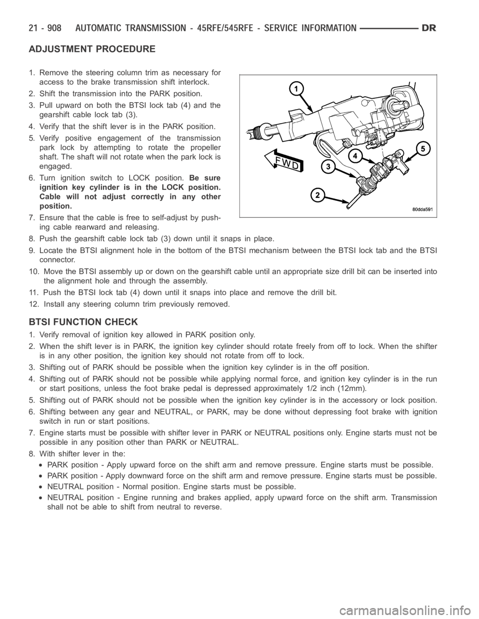
ADJUSTMENT PROCEDURE
1. Remove the steering column trim as necessary for
access to the brake transmission shift interlock.
2. Shift the transmission into the PARK position.
3. Pull upward on both the BTSI lock tab (4) and the
gearshift cable lock tab (3).
4. Verify that the shift lever is in the PARK position.
5. Verify positive engagement of the transmission
park lock by attempting to rotate the propeller
shaft. The shaft will not rotate when the park lock is
engaged.
6. Turn ignition switch to LOCK position.Be sure
ignition key cylinder is in the LOCK position.
Cable will not adjust correctly in any other
position.
7. Ensure that the cable is free to self-adjust by push-
ing cable rearward and releasing.
8. Push the gearshift cable lock tab (3) down until it snaps in place.
9. Locate the BTSI alignment hole in the bottom of the BTSI mechanism betweentheBTSIlocktabandtheBTSI
connector.
10. Move the BTSI assembly up or down on the gearshift cable until an appropriate size drill bit can be inserted into
the alignment hole and through the assembly.
11. Push the BTSI lock tab (4) down until it snaps into place and remove the drill bit.
12. Install any steering column trim previously removed.
BTSI FUNCTION CHECK
1. Verify removal of ignition key allowed in PARK position only.
2. When the shift lever is in PARK, the ignition key cylinder should rotate freely from off to lock. When the shifter
is in any other position, the ignition key should not rotate from off to lock.
3. Shifting out of PARK should be possible when the ignition key cylinder isin the off position.
4. Shifting out of PARK should not be possible while applying normal force,and ignition key cylinder is in the run
or start positions, unless the foot brake pedal is depressed approximately1/2inch(12mm).
5. Shifting out of PARK should not be possible when the ignition key cylinder is in the accessory or lock position.
6. Shifting between any gear and NEUTRAL, or PARK, may be done without depressing foot brake with ignition
switch in run or start positions.
7. Engine starts must be possible with shifter lever in PARK or NEUTRAL positions only. Engine starts must not be
possible in any position other than PARK or NEUTRAL.
8. With shifter lever in the:
PARK position - Apply upward force on the shift arm and remove pressure. Enginestartsmustbepossible.
PARK position - Apply downward force on the shift arm and remove pressure. Engine starts must be possible.
NEUTRAL position - Normal position. Engine starts must be possible.
NEUTRAL position - Engine running and brakes applied, apply upward force on the shift arm. Transmission
shall not be able to shift from neutral to reverse.
Page 3474 of 5267
SWITCH-TOW/HAUL OVERDRIVE
DESCRIPTION
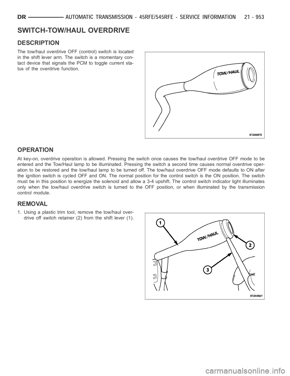
The tow/haul overdrive OFF (control) switch is located
in the shift lever arm. The switch is a momentary con-
tact device that signals the PCM to toggle current sta-
tus of the overdrive function.
OPERATION
At key-on, overdrive operation is allowed. Pressing the switch once causes the tow/haul overdrive OFF mode to be
entered and the Tow/Haul lamp to be illuminated. Pressing the switch a second time causes normal overdrive oper-
ationtoberestoredandthetow/haullamptobeturnedoff.Thetow/hauloverdrive OFF mode defaults to ON after
the ignition switch is cycled OFF and ON. The normal position for the control switch is the ON position. The switch
must be in this position to energize the solenoid and allow a 3-4 upshift. The control switch indicator light illuminates
only when the tow/haul overdrive switch is turned to the OFF position, or when illuminated by the transmission
control module.
REMOVAL
1. Using a plastic trim tool, remove the tow/haul over-
drive off switch retainer (2) from the shift lever (1).
Page 3481 of 5267
VALVE-SOLENOID SWITCH
DESCRIPTION
The Solenoid Switch Valve (SSV) is located in the valve body and controls the direction of the transmission fluid
when the L/R-TCC solenoid is energized.
OPERATION
The Solenoid Switch Valve controls line pressure from the LR-TCC solenoid. In 1st gear, the SSV will be in the
downshifted position, thus directing fluid to the L/R clutch circuit. In 2nd, 3rd, 4th, and 5th (if applicable) gears, the
solenoid switch valve will be in the upshifted position and directs the fluid into the torque converter clutch (TCC)
circuit.
When shifting into 1st gear, a special hydraulic sequence is performed to ensure SSV movement into the down-
shifted position. The L/R pressure switch is monitored to confirm SSV movement. If the movement is not confirmed
(the L/R pressure switch does not close), 2nd gear is substituted for 1st. ADTC will be set after three unsuccessful
attempts are made to get into 1st gear in one given key start.
Page 3496 of 5267
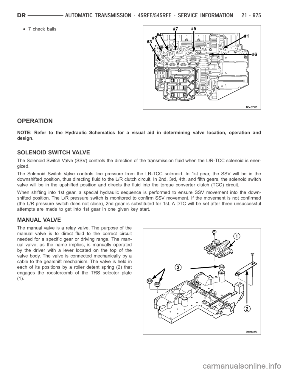
7 check balls
OPERATION
NOTE: Refer to the Hydraulic Schematics for a visual aid in determining valve location, operation and
design.
SOLENOID SWITCH VALVE
The Solenoid Switch Valve (SSV) controls the direction of the transmission fluid when the L/R-TCC solenoid is ener-
gized.
The Solenoid Switch Valve controls line pressure from the LR-TCC solenoid. In 1st gear, the SSV will be in the
downshifted position, thus directing fluid to the L/R clutch circuit. In 2nd, 3rd, 4th, and fifth gears, the solenoid switch
valve will be in the upshifted position and directs the fluid into the torque converter clutch (TCC) circuit.
When shifting into 1st gear, a special hydraulic sequence is performed to ensure SSV movement into the down-
shifted position. The L/R pressure switch is monitored to confirm SSV movement. If the movement is not confirmed
(the L/R pressure switch does not close), 2nd gear is substituted for 1st. ADTC will be set after three unsuccessful
attempts are made to get into 1st gear in one given key start.
MANUAL VALVE
The manual valve is a relay valve. The purpose of the
manual valve is to direct fluid to the correct circuit
needed for a specific gear or driving range. The man-
ual valve, as the name implies, is manually operated
by the driver with a lever located on the top of the
valve body. The valve is connected mechanically by a
cable to the gearshift mechanism. The valve is held in
each of its positions by a roller detent spring (2) that
engages the roostercomb of the TRS selector plate
(1).
Page 3734 of 5267
3.CHECK IF TTVA SHAFT END IS DAMAGED
Turn the ignition off to the lock position.
Remove the TTVA from the transmission per the Service Information. (Referto 21 - TRANSMISSION/TRANSAXLE/
AUTOMATIC - 48RE/THROTTLE VALVE ACTUATOR - REMOVAL)
Inspect the end of the TTVA shaft for cracks or damage.
NOTE: The end of the TTVA should be keyed or ”D” shaped and fit tightly over the Throttle Valve shaft.
Is the end of the TTVA shaft undamaged and fit tightly over the Throttle Valveshaft?
Ye s>>
Go To 4
No>>
Inspect the Throttle Valve shaft on the transmission for free movement. Ifthe Throttle valve does not
move freely, inspect internal transmission components related to the Throttle Valve and replace as nec-
essary. Replace the TTVA in either case. Refer to the Service Information.(Refer to 21 - TRANSMIS-
SION/TRANSAXLE/AUTOMATIC - 48RE/THROTTLE VALVE ACTUATOR - REMOVAL)
Perform RE TRANSMISSION VERIFICATION TEST VER - 1 (DIESEL). (Refer to 21 - TRANSMISSION/
TRANSAXLE/AUTOMATIC - 48RE - STANDARD PROCEDURE)
4.CHECK THE TRANSMISSION THROTTLE VALVE ACTUATOR
Properly support the TTVA to where the end of the shaft can be observed and reconnect the TTVA wiring harness.
NOTE: Each time the ignition is cycled to the on position, the ECM commands aTTVA internal calibration
procedure (autozero) to determine the zero position. Do not press on the accelerator pedal during this test.
Ignition on, engine not running.
Observe the output shaft of the TTVA during the autozero procedure.
After completion of the autozero procedure, while observing the TTVA shaft, press the accelerator pedal to full throt-
tle.
Does the TTVA internal motor move the TTVA shaft?
Ye s>>
Inspect the Throttle Valve shaft on the transmission for free movement. Ifthe Throttle valve does not
move freely, inspect internal transmission components related to the Throttle Valve and repair or replace
as necessary. (Refer to 21 - TRANSMISSION/TRANSAXLE/AUTOMATIC - 48RE/THROTTLE VALVE
ACTUATOR - REMOVAL)
Perform RE TRANSMISSION VERIFICATION TEST VER - 1 (DIESEL). (Refer to 21 - TRANSMISSION/
TRANSAXLE/AUTOMATIC - 48RE - STANDARD PROCEDURE)
No>>
Replace the TTVA per the Service Information.
Perform RE TRANSMISSION VERIFICATION TEST VER - 1 (DIESEL). (Refer to 21 - TRANSMISSION/
TRANSAXLE/AUTOMATIC - 48RE - STANDARD PROCEDURE)
5.INTERMITTENT WIRING AND CONNECTORS
The conditions necessary to set this DTC are not present at this time.
Using the schematics as a guide, visually inspect the related wiring harness. Look for any chafed, pierced, pinched,
or partially broken wires.
Visually inspect the related wiring harness connectors. Look for broken,bent, pushed out, or corroded terminals.
Wiggle the wiring and connectors while checking for any possible open or shorted circuits.
Check for any Service Information Tune-ups or Technical Service Bulletins that may apply.
Were there any problems found?
Ye s>>
Repair as necessary.
Perform RE TRANSMISSION VERIFICATION TEST VER - 1 (DIESEL). (Refer to 21 - TRANSMISSION/
TRANSAXLE/AUTOMATIC - 48RE - STANDARD PROCEDURE)
No>>
Te s t C o m p l e t e .
Page 3799 of 5267
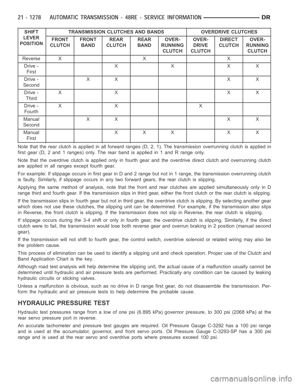
SHIFT
LEVER
POSITIONTRANSMISSION CLUTCHES AND BANDS OVERDRIVE CLUTCHES
FRONT
CLUTCHFRONT
BANDREAR
CLUTCHREAR
BANDOVER-
RUNNING
CLUTCHOVER-
DRIVE
CLUTCHDIRECT
CLUTCHOVER-
RUNNING
CLUTCH
ReverseXXX
Drive -
FirstXXXX
Drive -
SecondXX X X
Drive -
ThirdXX XX
Drive -
FourthXX X
Manual
SecondXX X X
Manual
FirstXXX X X
Note that the rear clutch is applied in all forward ranges (D, 2, 1). The transmission overrunning clutch is applied in
first gear (D, 2 and 1 ranges) only. The rear band is applied in 1 and R range only.
Note that the overdrive clutch is applied only in fourth gear and the overdrive direct clutch and overrunning clutch
are applied in all ranges except fourth gear.
For example: If slippage occurs in first gear in D and 2 range but not in 1 range, the transmission overrunning clutch
is faulty. Similarly, if slippage occurs in any two forward gears, the rearclutch is slipping.
Applying the same method of analysis, note that the front and rear clutchesare applied simultaneously only in D
range third and fourth gear. If the transmission slips in third gear, either the front clutch or the rear clutch is slipping.
Ifthetransmissionslipsinfourthgearbutnotinthirdgear,theoverdrive clutch is slipping. By selecting another gear
which does not use these clutches, the slipping unit can be determined. Forexample, if the transmission also slips
in Reverse, the front clutch is slipping. If the transmission does not slipin Reverse, the rear clutch is slipping.
If slippage occurs during the 3-4 shift or only in fourth gear, the overdrive clutch is slipping. Similarly, if the direct
clutch were to fail, the transmission would lose both reverse gear and overrun braking in 2 position (manual second
gear).
If the transmission will not shift to fourth gear, the control switch, overdrive solenoid or related wiring may also be
the problem cause.
This process of elimination can be used to identify a slipping unit and check operation. Proper use of the Clutch and
Band Application Chart is the key.
Although road test analysis will help determine the slipping unit, the actual cause of a malfunction usually cannot be
determined until hydraulic and air pressure tests are performed. Practically any condition can be caused by leaking
hydraulic circuits or sticking valves.
Unless a malfunction is obvious, such as no drive in D range first gear, do not disassemble the transmission. Per-
form the hydraulic and air pressure tests to help determine the probable cause.
HYDRAULIC PRESSURE TEST
Hydraulic test pressures range from a low of one psi (6.895 kPa) governor pressure, to 300 psi (2068 kPa) at the
rear servo pressure port in reverse.
An accurate tachometer and pressure test gauges are required. Oil Pressure Gauge C-3292 has a 100 psi range
and is used at the accumulator, governor, and front servo ports. Oil Pressure Gauge C-3293-SP has a 300 psi
range and is used at the rear servo and overdrive ports where pressures exceed 100 psi.
Page 3866 of 5267
SYSTEM-BRAKE TRANSMISSION SHIFT INTERLOCK
DESCRIPTION
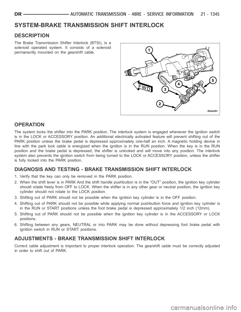
The Brake Transmission Shifter Interlock (BTSI), is a
solenoid operated system. It consists of a solenoid
permanently mounted on the gearshift cable.
OPERATION
The system locks the shifter into the PARK position. The interlock system is engaged whenever the ignition switch
is in the LOCK or ACCESSORY position. An additional electrically activated feature will prevent shifting out of the
PARK position unless the brake pedal is depressed approximately one-halfan inch. A magnetic holding device in
line with the park lock cable is energized when the ignition is in the RUN position. When the key is in the RUN
position and the brake pedal is depressed, the shifter is unlocked and willmove into any position. The interlock
system also prevents the ignition switch from being turned to the LOCK or ACCESSORY position, unless the shifter
is fully locked into the PARK position.
DIAGNOSIS AND TESTING - BRAKE TRANSMISSION SHIFT INTERLOCK
1. Verify that the key can only be removed in the PARK position.
2. When the shift lever is in PARK And the shift handle pushbutton is in the “OUT” position, the ignition key cylinder
should rotate freely from OFF to LOCK. When the shifter is in any other gear or neutral position, the ignition key
cylinder should not rotate to the LOCK position.
3. Shifting out of PARK should not be possible when the ignition key cylinder is in the OFF position.
4. Shifting out of PARK should not be possible while applying normal pushbutton force and ignition key cylinder is
in the RUN or START positions unless the foot brake pedal is depressed approximately 1/2 inch (12mm).
5. Shifting out of PARK should not be possible when the ignition key cylinderisintheACCESSORYorLOCK
positions.
6. Shifting between any gears, NEUTRAL or into PARK may be done without depressing foot brake pedal with
ignition switch in RUN or START positions.
ADJUSTMENTS - BRAKE TRANSMISSION SHIFT INTERLOCK
Correct cable adjustment is important to proper interlock operation. Thegearshift cable must be correctly adjusted
in order to shift out of PARK.
Page 3867 of 5267
ADJUSTMENT PROCEDURE
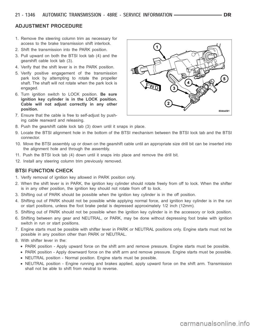
1. Remove the steering column trim as necessary for
access to the brake transmission shift interlock.
2. Shift the transmission into the PARK position.
3. Pull upward on both the BTSI lock tab (4) and the
gearshift cable lock tab (3).
4. Verify that the shift lever is in the PARK position.
5. Verify positive engagement of the transmission
park lock by attempting to rotate the propeller
shaft. The shaft will not rotate when the park lock is
engaged.
6. Turn ignition switch to LOCK position.Be sure
ignition key cylinder is in the LOCK position.
Cable will not adjust correctly in any other
position.
7. Ensure that the cable is free to self-adjust by push-
ing cable rearward and releasing.
8. Push the gearshift cable lock tab (3) down until it snaps in place.
9. Locate the BTSI alignment hole in the bottom of the BTSI mechanism betweentheBTSIlocktabandtheBTSI
connector.
10. Move the BTSI assembly up or down on the gearshift cable until an appropriate size drill bit can be inserted into
the alignment hole and through the assembly.
11. Push the BTSI lock tab (4) down until it snaps into place and remove the drill bit.
12. Install any steering column trim previously removed.
BTSI FUNCTION CHECK
1. Verify removal of ignition key allowed in PARK position only.
2. When the shift lever is in PARK, the ignition key cylinder should rotate freely from off to lock. When the shifter
is in any other position, the ignition key should not rotate from off to lock.
3. Shifting out of PARK should be possible when the ignition key cylinder isin the off position.
4. Shifting out of PARK should not be possible while applying normal force,and ignition key cylinder is in the run
or start positions, unless the foot brake pedal is depressed approximately1/2inch(12mm).
5. Shifting out of PARK should not be possible when the ignition key cylinder is in the accessory or lock position.
6. Shifting between any gear and NEUTRAL, or PARK, may be done without depressing foot brake with ignition
switch in run or start positions.
7. Engine starts must be possible with shifter lever in PARK or NEUTRAL positions only. Engine starts must not be
possible in any position other than PARK or NEUTRAL.
8. With shifter lever in the:
PARK position - Apply upward force on the shift arm and remove pressure. Enginestartsmustbepossible.
PARK position - Apply downward force on the shift arm and remove pressure. Engine starts must be possible.
NEUTRAL position - Normal position. Engine starts must be possible.
NEUTRAL position - Engine running and brakes applied, apply upward force on the shift arm. Transmission
shall not be able to shift from neutral to reverse.