2006 DODGE RAM SRT-10 key
[x] Cancel search: keyPage 2845 of 5267
P0884-POWER UP AT SPEED
For a complete wiring diagramRefer to Section 8W.
When Monitored:
One time after each controller reset. Note: the Transmission Control Module is integrated with Powertrain Con-
trol Module. The Transmission Control Module has separate powers and grounds specifically to its portion of
the PCM.
Set Condition:
This DTC will set if the PCM powers up and senses the vehicle in a valid forward gear (no PRNDL DTCs) with
a output speed above 800 RPM, approximately 32 Kmh or 20 mph.
Possible Causes
INTERMITTENT POWER AND GROUND CIRCUITS
Always perform the 42RLE Pre-Diagnostic Troubleshooting procedure before proceeding. (Refer to 21 -
TRANSMISSION/TRANSAXLE/AUTOMATIC - 42RLE - STANDARD PROCEDURE)
Theory of Operation
If a vehicle loses power to the PCM, the vehicle will go to the 2nd gear mode since there is no power available to
control the transmission solenoids. However if power is restored, the PCMwill power-up and normal operation will
be restored. This DTC identifies that power to the PCM was restored when thegear selector was in a
Driveposi-
tion while the vehicle was moving at speeds above 32 Kmh (20 mph). If a customer shifts to Neutral and cycles the
ignition key and quickly shifts to
Drivewhile moving before the PCM comes out of its START ROUTINE, the DTC
can be set. Therefore it is critical that this DTC diagnosis repair procedure should only be used if the vehicle is
experiencing intermittent 2nd gear operation and subsequently a return to normal operation during normal driving.
The transmission will not be placed in Limp-in. This is an informational DTC to be used when attempting to diag-
nose an intermittent 2nd gear operation and subsequent return to normal transmission operation.
Diagnostic Test
1.CHECK THE POWER AND GROUND CIRCUITS
This DTC is set when the PCM is initialized while the vehicle is moving in a valid forward gear. This is usually
caused by a momentary loss of power to the Transmission portion of the PCM.
CAUTION: Do not probe the PCM harness connectors. Probing the PCM harness connectors will damage
the PCM terminals resulting in poor terminal to pin connection. Install Miller tool #8815 to perform diagno-
sis.
NOTE: Due to the integration of the Powertrain and Transmission Control Modules, the transmission part of
the PCM has its own specific power and ground circuits.
Check all of the Fused B(+), Fused Ignition Switch Output, and Ground circuits related to the PCM for an intermit-
tent open or short to ground.
Perform a wiggle test on all wiring and connectors pertaining to the PCM while looking for shorted or open circuits.
With the scan tool, check the DTC EVENT DATA to help identify the conditionsin which the DTC was set.
If there are no possible causes remaining, view repair.
Repair
Repair as necessary.
Perform 42RLE TRANSMISSION VERIFICATION TEST - VER 1. (Refer to 21 - TRANSMISSION/
TRANSAXLE/AUTOMATIC - 42RLE - STANDARD PROCEDURE)
Page 2847 of 5267
When Monitored:
One time after a reset (ignition key turned to the RUN position or after cranking engine).
Set Condition:
A fault is set if voltage greater than 4.5 volts is detected for 7 msec on any of the pressure switch circuits
before the relay is energized. The transmission is placed in Limp-In. The MIL is on after 10 seconds. of vehicle
operation.
Possible Causes
(T47) 2/4 PRESSURE SWITCH SENSE CIRCUIT SHORT TO VOLTAGE
(T50) L/R PRESSURE SWITCH SENSE CIRCUIT SHORT TO VOLTAGE
(T9) OD PRESSURE SWITCH SENSE CIRCUIT SHORT TO VOLTAGE
POWERTRAIN CONTROL MODULE
Always perform the 42RLE Pre-Diagnostic Troubleshooting procedure before proceeding. (Refer to 21 -
TRANSMISSION/TRANSAXLE/AUTOMATIC - 42RLE - STANDARD PROCEDURE)
Theory of Operation
The transmission relay is used to supply power to the solenoid pack when in normal operating mode and to turn off
power to produce transmission
limp-inmode. The relay output (which supplies power to the solenoid pack) is fed
back to the controller. It is referred to as SWITCHED BATTERY. After a controller reset (ignition key turned to the
RUN position or after cranking engine), the controller verifies that the relay contacts are open by checking for no
voltage on Switched battery line (transmission control relay output) before the relay is energized. After switched
battery is verified for no voltage, the voltage of each of the solenoid packpressure switches is also checked. Since
the solenoid pack is not powered up, there should be no voltage on any of the pressure switches.
Diagnostic Test
1.CHECK TO SEE IF DTC P0890 IS PRESENT
With the scan tool, view DTCs.
Is the status Active for this DTC or is the STARTS SINCE SET counter set at 0?
Ye s>>
Go To 2
No>>
Go To 5
Page 2881 of 5267
When Monitored:
After a reset (ignition key turned to the RUN position).
Set Condition:
The checksum of the battery backed RAM does not match the stored checksum. Set Time: Less than 7 msec.
Possible Causes
BATTERY WAS DISCONNECTED
PCM WAS REPLACED OR DISCONNECTED
QUICK LEARN WAS PERFORMED
(A919) FUSED B+ CIRCUIT TO PCM OPEN
(Z908 and Z977) GROUND CIRCUIT OPEN
Always perform the 42RLE Pre-Diagnostic Troubleshooting procedure before proceeding. (Refer to 21 -
TRANSMISSION/TRANSAXLE/AUTOMATIC - 42RLE - STANDARD PROCEDURE)
Theory of Operation
Note: This is not a fault code. It exists to provide reference information only. A battery backed RAM is used to
maintain some learned values. When the battery is disconnected, this memory is lost. When the battery is recon-
nected, the loss of learned values will be detected by the controller. The code will be set and the learned values will
be initialized to known constants and the learning process will continue.Setting the code has no effect except for
re-initialization of learned values.
Diagnostic Test
1.BATTERY WAS DISCONNECTED
Has the battery been disconnected, lost it’s charge, or been replaced recently?
Ye s>>
Disconnecting or replacing the battery will set this DTC. Erase the DTC.
Perform 42RLE TRANSMISSION VERIFICATION TEST - VER 1. (Refer to 21 - TRANSMISSION/
TRANSAXLE/AUTOMATIC - 42RLE - STANDARD PROCEDURE)
No>>
Go To 2
2.WAS QUICK LEARN PERFORMED
Has a Quick Learn procedure been performed?
Ye s>>
Performing Quick Learn will set this DTC. Erase the DTC.
Perform 42RLE TRANSMISSION VERIFICATION TEST - VER 1. (Refer to 21 - TRANSMISSION/
TRANSAXLE/AUTOMATIC - 42RLE - STANDARD PROCEDURE)
No>>
Go To 3
3.PCM REPLACED OR DISCONNECTED
Has the PCM been replaced or disconnected?
Ye s>>
Replacing or disconnecting the PCM will set this DTC. Erase the DTC.
Perform 42RLE TRANSMISSION VERIFICATION TEST - VER 1. (Refer to 21 - TRANSMISSION/
TRANSAXLE/AUTOMATIC - 42RLE - STANDARD PROCEDURE)
No>>
Go To 4
Page 3010 of 5267
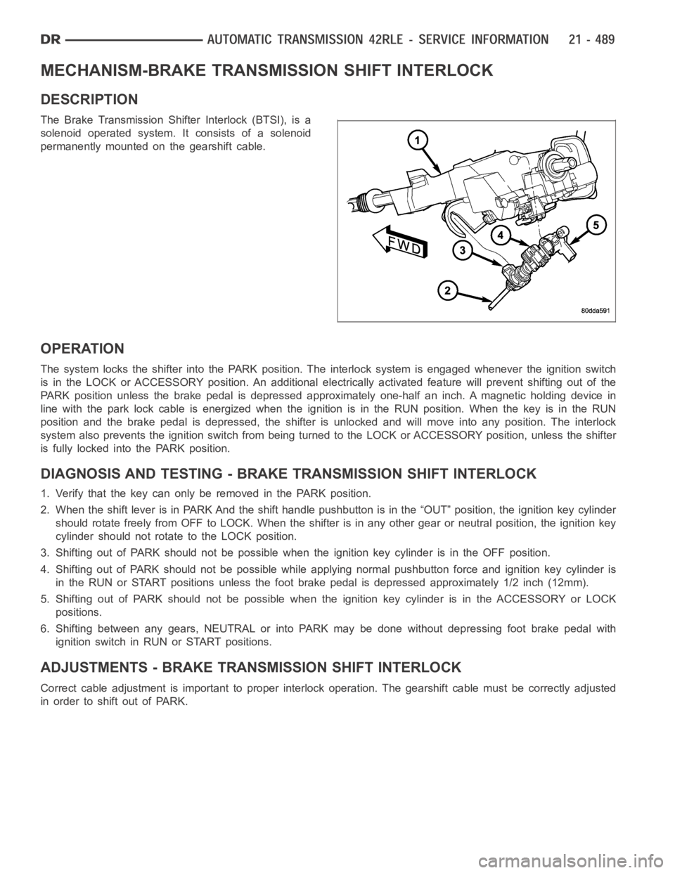
MECHANISM-BRAKE TRANSMISSION SHIFT INTERLOCK
DESCRIPTION
The Brake Transmission Shifter Interlock (BTSI), is a
solenoid operated system. It consists of a solenoid
permanently mounted on the gearshift cable.
OPERATION
The system locks the shifter into the PARK position. The interlock system is engaged whenever the ignition switch
is in the LOCK or ACCESSORY position. An additional electrically activated feature will prevent shifting out of the
PARK position unless the brake pedal is depressed approximately one-halfan inch. A magnetic holding device in
line with the park lock cable is energized when the ignition is in the RUN position. When the key is in the RUN
position and the brake pedal is depressed, the shifter is unlocked and willmove into any position. The interlock
system also prevents the ignition switch from being turned to the LOCK or ACCESSORY position, unless the shifter
is fully locked into the PARK position.
DIAGNOSIS AND TESTING - BRAKE TRANSMISSION SHIFT INTERLOCK
1. Verify that the key can only be removed in the PARK position.
2. When the shift lever is in PARK And the shift handle pushbutton is in the “OUT” position, the ignition key cylinder
should rotate freely from OFF to LOCK. When the shifter is in any other gear or neutral position, the ignition key
cylinder should not rotate to the LOCK position.
3. Shifting out of PARK should not be possible when the ignition key cylinder is in the OFF position.
4. Shifting out of PARK should not be possible while applying normal pushbutton force and ignition key cylinder is
in the RUN or START positions unless the foot brake pedal is depressed approximately 1/2 inch (12mm).
5. Shifting out of PARK should not be possible when the ignition key cylinderisintheACCESSORYorLOCK
positions.
6. Shifting between any gears, NEUTRAL or into PARK may be done without depressing foot brake pedal with
ignition switch in RUN or START positions.
ADJUSTMENTS - BRAKE TRANSMISSION SHIFT INTERLOCK
Correct cable adjustment is important to proper interlock operation. Thegearshift cable must be correctly adjusted
in order to shift out of PARK.
Page 3011 of 5267
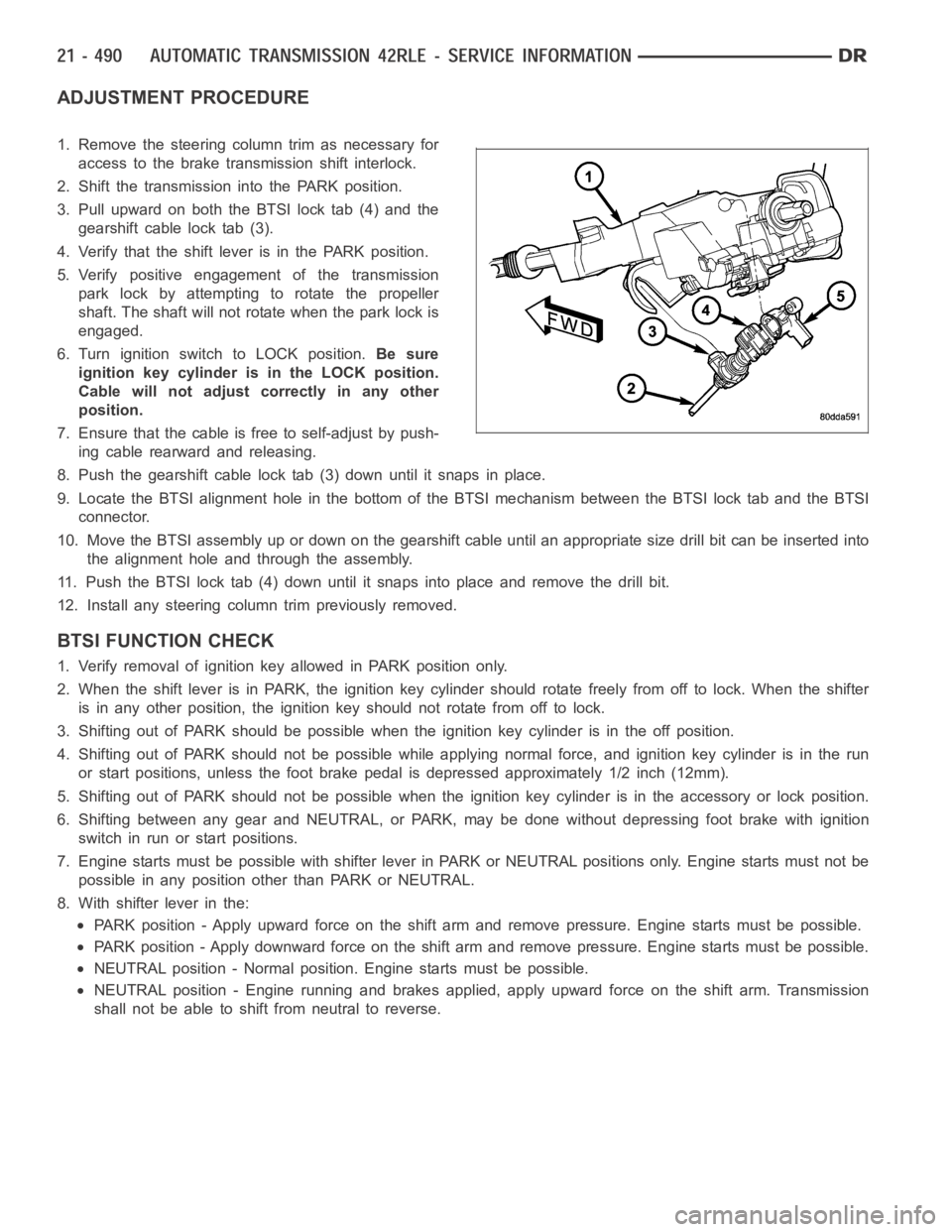
ADJUSTMENT PROCEDURE
1. Remove the steering column trim as necessary for
access to the brake transmission shift interlock.
2. Shift the transmission into the PARK position.
3. Pull upward on both the BTSI lock tab (4) and the
gearshift cable lock tab (3).
4. Verify that the shift lever is in the PARK position.
5. Verify positive engagement of the transmission
park lock by attempting to rotate the propeller
shaft. The shaft will not rotate when the park lock is
engaged.
6. Turn ignition switch to LOCK position.Be sure
ignition key cylinder is in the LOCK position.
Cable will not adjust correctly in any other
position.
7. Ensure that the cable is free to self-adjust by push-
ing cable rearward and releasing.
8. Push the gearshift cable lock tab (3) down until it snaps in place.
9. Locate the BTSI alignment hole in the bottom of the BTSI mechanism betweentheBTSIlocktabandtheBTSI
connector.
10. Move the BTSI assembly up or down on the gearshift cable until an appropriate size drill bit can be inserted into
the alignment hole and through the assembly.
11. Push the BTSI lock tab (4) down until it snaps into place and remove the drill bit.
12. Install any steering column trim previously removed.
BTSI FUNCTION CHECK
1. Verify removal of ignition key allowed in PARK position only.
2. When the shift lever is in PARK, the ignition key cylinder should rotate freely from off to lock. When the shifter
is in any other position, the ignition key should not rotate from off to lock.
3. Shifting out of PARK should be possible when the ignition key cylinder isin the off position.
4. Shifting out of PARK should not be possible while applying normal force,and ignition key cylinder is in the run
or start positions, unless the foot brake pedal is depressed approximately1/2inch(12mm).
5. Shifting out of PARK should not be possible when the ignition key cylinder is in the accessory or lock position.
6. Shifting between any gear and NEUTRAL, or PARK, may be done without depressing foot brake with ignition
switch in run or start positions.
7. Engine starts must be possible with shifter lever in PARK or NEUTRAL positions only. Engine starts must not be
possible in any position other than PARK or NEUTRAL.
8. With shifter lever in the:
PARK position - Apply upward force on the shift arm and remove pressure. Enginestartsmustbepossible.
PARK position - Apply downward force on the shift arm and remove pressure. Engine starts must be possible.
NEUTRAL position - Normal position. Engine starts must be possible.
NEUTRAL position - Engine running and brakes applied, apply upward force on the shift arm. Transmission
shall not be able to shift from neutral to reverse.
Page 3071 of 5267
SWITCH-TOW/HAUL OVERDRIVE
DESCRIPTION
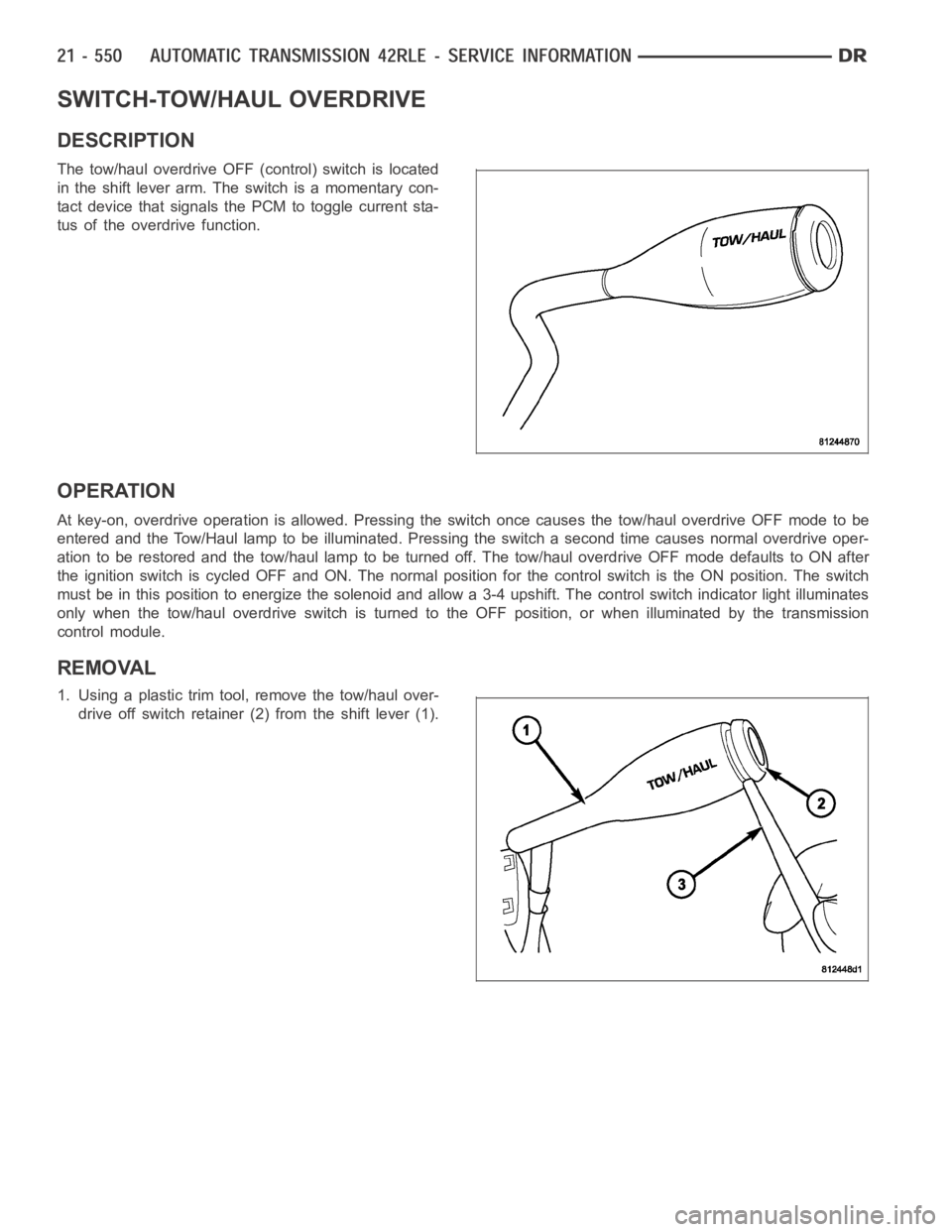
The tow/haul overdrive OFF (control) switch is located
in the shift lever arm. The switch is a momentary con-
tact device that signals the PCM to toggle current sta-
tus of the overdrive function.
OPERATION
At key-on, overdrive operation is allowed. Pressing the switch once causes the tow/haul overdrive OFF mode to be
entered and the Tow/Haul lamp to be illuminated. Pressing the switch a second time causes normal overdrive oper-
ationtoberestoredandthetow/haullamptobeturnedoff.Thetow/hauloverdrive OFF mode defaults to ON after
the ignition switch is cycled OFF and ON. The normal position for the control switch is the ON position. The switch
must be in this position to energize the solenoid and allow a 3-4 upshift. The control switch indicator light illuminates
only when the tow/haul overdrive switch is turned to the OFF position, or when illuminated by the transmission
control module.
REMOVAL
1. Using a plastic trim tool, remove the tow/haul over-
drive off switch retainer (2) from the shift lever (1).
Page 3273 of 5267
When Monitored:
When the ignition is turned from
OFFposition toRUNposition and/or the ignition is turned fromSTART
position toRUNposition.
Set Condition:
This DTC is set if the Powertrain Control Module senses voltage on any of thepressure switch inputs prior to
the Transmission Control Output circuit being energized.
Possible Causes
PRESSURE SWITCH SENSE CIRCUITS SHORT TO VOLTAGE
TRANSMISSION SOLENOID/TRS ASSEMBLY
POWERTRAIN CONTROL MODULE
Always perform the 45RFE/545RFE Pre-Diagnostic Troubleshooting Procedure before proceeding. (Refer to
21 - TRANSMISSION/TRANSAXLE/AUTOMATIC - 45RFE/545RFE - STANDARD PROCEDURE)
Theory of Operation
The Totally Integrated Control Module (TIPM) replaces the Transmission control relay. The Transmission Control
Output circuit It is used to supply power to the solenoids and pressure switches (Transmission Solenoid/TRS
Assembly) when the transmission is in normal operating mode. When the Transmission Control Output circuit is off,
no power is supplied and the transmission.
Immediately after a controller reset (ignition key turned to the
runposition or after cranking engine), the TCM ver-
ifies that the Transmission Control Output circuits are open by checking for no voltage at the transmission control
output terminals at the PCM. After this is verified, the voltage at the pressure switches are checked. There should
be no voltage on the pressure switches at this time. The PCM will then activate the relay.
Diagnostic Test
1.CHECK FOR TIPM TCM DTCS
With the scan tool under TIPM, check for TCM Power Control DTCs.
Are there any TCM Power Control DTCs present?
Ye s>>
Refer to the Transmission category and perform the appropriate symptom.
No>>
Go To 2
2.CHECK TO SEE IF DTC P0890 IS PRESENT
With the scan tool, Check the STARTS SINCE SET counter for P0890.
NOTE: This counter only applies to the last DTC set.
Is the
Starts Since Setcounter set at 0?
Ye s>>
Go To 3
No>>
Go To 5
Page 3428 of 5267
SYSTEM-BRAKE TRANSMISSION SHIFT INTERLOCK
DESCRIPTION
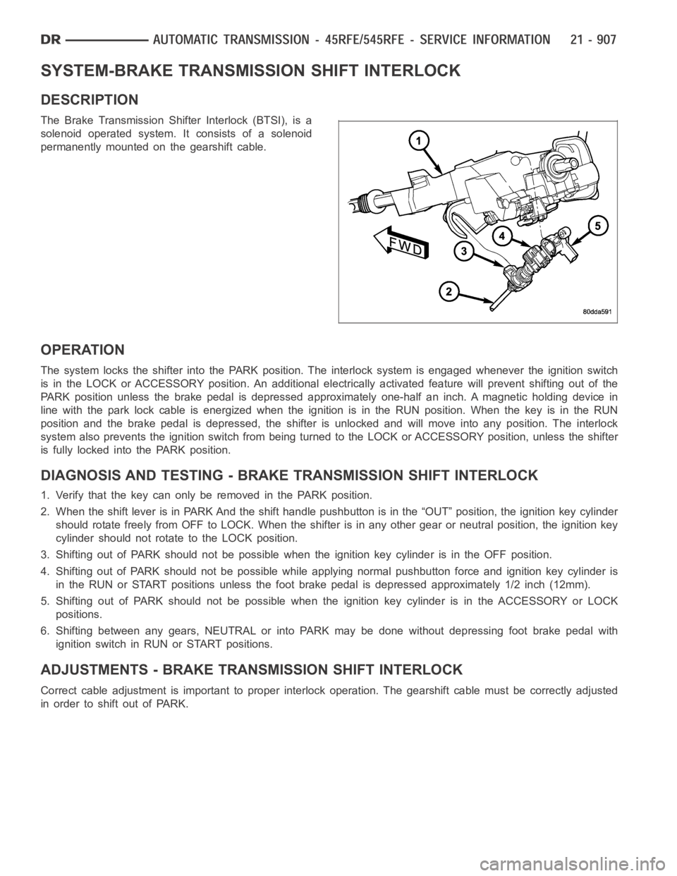
The Brake Transmission Shifter Interlock (BTSI), is a
solenoid operated system. It consists of a solenoid
permanently mounted on the gearshift cable.
OPERATION
The system locks the shifter into the PARK position. The interlock system is engaged whenever the ignition switch
is in the LOCK or ACCESSORY position. An additional electrically activated feature will prevent shifting out of the
PARK position unless the brake pedal is depressed approximately one-halfan inch. A magnetic holding device in
line with the park lock cable is energized when the ignition is in the RUN position. When the key is in the RUN
position and the brake pedal is depressed, the shifter is unlocked and willmove into any position. The interlock
system also prevents the ignition switch from being turned to the LOCK or ACCESSORY position, unless the shifter
is fully locked into the PARK position.
DIAGNOSIS AND TESTING - BRAKE TRANSMISSION SHIFT INTERLOCK
1. Verify that the key can only be removed in the PARK position.
2. When the shift lever is in PARK And the shift handle pushbutton is in the “OUT” position, the ignition key cylinder
should rotate freely from OFF to LOCK. When the shifter is in any other gear or neutral position, the ignition key
cylinder should not rotate to the LOCK position.
3. Shifting out of PARK should not be possible when the ignition key cylinder is in the OFF position.
4. Shifting out of PARK should not be possible while applying normal pushbutton force and ignition key cylinder is
in the RUN or START positions unless the foot brake pedal is depressed approximately 1/2 inch (12mm).
5. Shifting out of PARK should not be possible when the ignition key cylinderisintheACCESSORYorLOCK
positions.
6. Shifting between any gears, NEUTRAL or into PARK may be done without depressing foot brake pedal with
ignition switch in RUN or START positions.
ADJUSTMENTS - BRAKE TRANSMISSION SHIFT INTERLOCK
Correct cable adjustment is important to proper interlock operation. Thegearshift cable must be correctly adjusted
in order to shift out of PARK.